US4841273A - High temperature sensing apparatus - Google Patents
High temperature sensing apparatus Download PDFInfo
- Publication number
- US4841273A US4841273A US07/134,881 US13488187A US4841273A US 4841273 A US4841273 A US 4841273A US 13488187 A US13488187 A US 13488187A US 4841273 A US4841273 A US 4841273A
- Authority
- US
- United States
- Prior art keywords
- sensing device
- temperature sensing
- ceramic member
- ceramic
- temperature
- Prior art date
- Legal status (The legal status is an assumption and is not a legal conclusion. Google has not performed a legal analysis and makes no representation as to the accuracy of the status listed.)
- Expired - Fee Related
Links
- 239000000919 ceramic Substances 0.000 claims abstract description 35
- 239000002184 metal Substances 0.000 claims abstract description 4
- 229910052751 metal Inorganic materials 0.000 claims abstract description 4
- PCHJSUWPFVWCPO-UHFFFAOYSA-N gold Chemical compound [Au] PCHJSUWPFVWCPO-UHFFFAOYSA-N 0.000 claims description 6
- 239000010931 gold Substances 0.000 claims description 6
- 229910052737 gold Inorganic materials 0.000 claims description 6
- 230000005284 excitation Effects 0.000 claims description 2
- 239000004020 conductor Substances 0.000 claims 5
- 239000010970 precious metal Substances 0.000 claims 1
- 239000000758 substrate Substances 0.000 abstract description 28
- 239000000523 sample Substances 0.000 abstract description 11
- BASFCYQUMIYNBI-UHFFFAOYSA-N platinum Chemical compound [Pt] BASFCYQUMIYNBI-UHFFFAOYSA-N 0.000 description 10
- 229910052697 platinum Inorganic materials 0.000 description 5
- 239000000853 adhesive Substances 0.000 description 4
- 230000001070 adhesive effect Effects 0.000 description 4
- 239000010408 film Substances 0.000 description 4
- 238000003466 welding Methods 0.000 description 3
- 239000004593 Epoxy Substances 0.000 description 2
- 230000004075 alteration Effects 0.000 description 2
- PNEYBMLMFCGWSK-UHFFFAOYSA-N aluminium oxide Inorganic materials [O-2].[O-2].[O-2].[Al+3].[Al+3] PNEYBMLMFCGWSK-UHFFFAOYSA-N 0.000 description 2
- 229910010293 ceramic material Inorganic materials 0.000 description 2
- 238000010304 firing Methods 0.000 description 2
- 230000004048 modification Effects 0.000 description 2
- 238000012986 modification Methods 0.000 description 2
- 230000001681 protective effect Effects 0.000 description 2
- 238000004544 sputter deposition Methods 0.000 description 2
- 239000010409 thin film Substances 0.000 description 2
- 238000004140 cleaning Methods 0.000 description 1
- 230000000694 effects Effects 0.000 description 1
- 238000010438 heat treatment Methods 0.000 description 1
- 238000004519 manufacturing process Methods 0.000 description 1
- 239000002923 metal particle Substances 0.000 description 1
- 229910052594 sapphire Inorganic materials 0.000 description 1
- 239000010980 sapphire Substances 0.000 description 1
Images

Classifications
-
- G—PHYSICS
- G01—MEASURING; TESTING
- G01K—MEASURING TEMPERATURE; MEASURING QUANTITY OF HEAT; THERMALLY-SENSITIVE ELEMENTS NOT OTHERWISE PROVIDED FOR
- G01K7/00—Measuring temperature based on the use of electric or magnetic elements directly sensitive to heat ; Power supply therefor, e.g. using thermoelectric elements
- G01K7/16—Measuring temperature based on the use of electric or magnetic elements directly sensitive to heat ; Power supply therefor, e.g. using thermoelectric elements using resistive elements
- G01K7/18—Measuring temperature based on the use of electric or magnetic elements directly sensitive to heat ; Power supply therefor, e.g. using thermoelectric elements using resistive elements the element being a linear resistance, e.g. platinum resistance thermometer
Definitions
- This application relates to the art of temperature sensing and, more particularly, to sensing of very high temperatures.
- the invention is particularly applicable to apparatus used for sensing temperatures in ovens or the like, and will be described with particular reference thereto. However, it will be appreciated that the invention has broader aspects, and can be used for sensing temperatures in other environments.
- the temperature gradient between the opposite end portions of a temperature sensing probe is often very large. This large temperature gradient, and the extremely high temperatures at the sensing end of the probe, often cause failure of the probe or significantly reduce its life.
- a temperature sensing probe includes a pair of elongated spaced-apart electrically conductive strips fused along their entire length to a ceramic substrate.
- the conductive strips are connected at one end thereof to a platinum resistance thermometer element that is adhesively bonded to the ceramic substrate.
- the electrically conductive strips comprise a conductive thick film ceramic material that is deposited on the ceramic substrate and then fired for fusing same to the substrate.
- the conductive strips are connected with the platinum resistance thermometer by gold wires.
- the opposite or cooler end portions of the conductive strips, opposite from the platinum resistance thermometer chip, are connected to an electrical terminal with a conductive adhesive, such as conductive epoxy.
- the assembled ceramic substrate is inserted into a metal sheath to form a temperature probe.
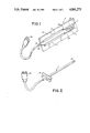
- FIG. 1 is a perspective illustration of a temperature sensing apparatus constructed in accordance with the present application
- FIG. 2 is an illustration of a protective sheath having the assembly of FIG. 1 received therein;
- FIG. 3 is a partial perspective illustration showing terminals connected directly to the cool end of the ceramic substrate.
- FIG. 4 is a side elevational view of a terminal that can be connected directly to the cool end of the ceramic substrate.
- FIG. 1 shows a substantially flat and rectangular ceramic substrate A of alumina or the like.
- Substrate A has a substantially flat surface 10 extending along the entire length thereof.
- a pair of elongated spaced-apart conductive strips 12, 14 are provided on substrate surface 10.
- conductive strips 12, 14 are formed by laying down strips of a conductive ceramic glaze, and then firing same to fuse the glaze strips along their entire length to the substrate surface.
- conductive strips 12, 14 are conductive thick films. With both substrate A and conductive strips 12, 14 being of ceramic material and fused together, the coefficients of expansion of same are close enough that fractures in the conductive strips are unlikely.
- a platinum resistance thermometer chip or die B is attached to substrate surface 10 as by the use of a ceramic adhesive 16.
- Chip B defines a variable resistance means whose resistance varies with temperature.
- a platinum resistance circuit 18 is deposited on chip B in the form of a thin film as by sputtering, and is photolithographically shaped. Obviously, other types of sensing devices could be used.
- Gold wires 22, 24 are connected to conductive strips 12, 14, and to resistance circuit 18, by ultrasonic welding, by thermocompression welding (heat and pressure), of by thermosonic welding (heat and ultrasonic power). This makes the high temperature end portion of the apparatus very reliable.
- the gold wires and ultrasonic welds define connecting means for connecting strips 12, 14 in electrically conductive relationship with resistance circuit 18.
- Ceramic substrate A is receivable in a protective metal sheath C to form a temperature probe.
- the diameter of sheath C is slightly greater than the width of ceramic substrate A so that the entire length of substrate A is receivable in sheath C down the center thereof.
- a suitable mounting bracket 36 is provided on sheath C for mounting same in a desired location with end portion 38 thereof positioned in the desired location for sensing the temperature of an environment.
- Variable resistance means B is located within sheath C adjacent end portion 38 thereof.
- substrate A being substantially flat and rectangular, it will be recognized that other shapes are also possible.
- substrate A could have a generally triangular cross-sectional shape, with surface 10 being one of the flat surfaces of the triangle.
- Conductive strips 12, 14 extend over a major portion of the length of ceramic substrate A, and variable resistance means B is mounted adjacent one end portion of substrate A.
- Gold wires 22, 24 provide a highly reliable connecting means for connecting variable resistance means to the conductive strips.
- Resistance circuit 18 is mounted on a ceramic die which in turn is adhesively bonded to substrate A.
- conductive strips 12, 14 may be laid down on substrate A as a thick film by use of a ceramic glaze conductive ink. The substrate and thick film strips are fired to fuse same together.
- the firing temperature may vary and, by way of example only, can be around 850° C.
- Resistance circuit 18 is provided on its ceramic die as by sputtering in a known manner to form a thin film.
- the die may be alumina or sapphire.
- Conductive ceramic glazes and adhesives are made by filling same with conductive metal particles.
- the variable resistance means may be connected in one leg of a wheatstone bridge for measuring the excitation current flowing through the resistant circuit.
- the temperature probe of the present application may be used to signal a solenoid for locking a door shut in a self-cleaning oven. The probe could also be used for turning a heating element off or for modulating same to maintain a desired temperature.
- the resistance of the conductive strips 12, 14 is small compared to the resistance of thermometer die B, and has a negligible effect on the temperature performance of die B.
- FIG. 3 shows generally U-shaped connector terminals D, E having spaced-apart legs 40, 42 and outwardly curved ends 44, 46. Terminals D, E are mounted in a connector body, within which wires are suitably connected to terminals D, E. This allows the cool end of the device to be directly inserted into terminals D, E. Legs 40, 42 resiliently grip substrate A, and frictionally engage strips 12, 14 in conductive relationship.
- FIG. 4 shows a connector body F enclosing spaced-apart blades 50, 52 having outwardly curved outer end portions 54, 56 between which an entrance socket 60 is defined.
- the inner end portions of blades 50, 52 are turned inwardly and secured together in clamping relationship to wire 62 by fastener means 64.
- the spacing between blades 50, 52 is less than the thickness of substrate A and strips 12, 14 so that the substrate and strips are resiliently gripped between the blades.
Abstract
Description
Claims (8)
Priority Applications (4)
| Application Number | Priority Date | Filing Date | Title |
|---|---|---|---|
| US07/134,881 US4841273A (en) | 1987-12-18 | 1987-12-18 | High temperature sensing apparatus |
| CA000577119A CA1314730C (en) | 1987-12-18 | 1988-09-12 | High temperature sensing apparatus |
| EP88630220A EP0322338A3 (en) | 1987-12-18 | 1988-12-01 | High temperature sensing apparatus |
| JP63317579A JPH01200601A (en) | 1987-12-18 | 1988-12-15 | Temperature detector |
Applications Claiming Priority (1)
| Application Number | Priority Date | Filing Date | Title |
|---|---|---|---|
| US07/134,881 US4841273A (en) | 1987-12-18 | 1987-12-18 | High temperature sensing apparatus |
Publications (1)
| Publication Number | Publication Date |
|---|---|
| US4841273A true US4841273A (en) | 1989-06-20 |
Family
ID=22465435
Family Applications (1)
| Application Number | Title | Priority Date | Filing Date |
|---|---|---|---|
| US07/134,881 Expired - Fee Related US4841273A (en) | 1987-12-18 | 1987-12-18 | High temperature sensing apparatus |
Country Status (4)
| Country | Link |
|---|---|
| US (1) | US4841273A (en) |
| EP (1) | EP0322338A3 (en) |
| JP (1) | JPH01200601A (en) |
| CA (1) | CA1314730C (en) |
Cited By (10)
| Publication number | Priority date | Publication date | Assignee | Title |
|---|---|---|---|---|
| US5123752A (en) * | 1991-04-15 | 1992-06-23 | Eastman Kodak Company | Wear resistant temperature sensing device |
| US5726624A (en) * | 1996-07-01 | 1998-03-10 | Honeywell Inc. | Temperature sensor with internal rigid substrate |
| US6341892B1 (en) * | 2000-02-03 | 2002-01-29 | George Schmermund | Resistance thermometer probe |
| US6354736B1 (en) * | 1999-03-24 | 2002-03-12 | Honeywell International Inc. | Wide temperature range RTD |
| US6380840B1 (en) | 1996-05-24 | 2002-04-30 | Heraeus Electro-Nite International N.V. | Temperature sensor with measuring resistor |
| US20070234818A1 (en) * | 2006-04-06 | 2007-10-11 | Sauer-Danfoss Aps | Object having a layer of conducting material forming a sensing device |
| US20100033295A1 (en) * | 2008-08-05 | 2010-02-11 | Therm-O-Disc, Incorporated | High temperature thermal cutoff device |
| KR20110044880A (en) * | 2008-08-07 | 2011-05-02 | 에프코스 아게 | Sensor device and manufacturing method |
| US9171654B2 (en) | 2012-06-15 | 2015-10-27 | Therm-O-Disc, Incorporated | High thermal stability pellet compositions for thermal cutoff devices and methods for making and use thereof |
| US10247619B2 (en) * | 2015-05-01 | 2019-04-02 | Vishay Measurements Group, Inc. | Resistance temperature detector with medium temperature coefficient and high linearity |
Families Citing this family (2)
| Publication number | Priority date | Publication date | Assignee | Title |
|---|---|---|---|---|
| FR2836205B1 (en) * | 2002-02-15 | 2004-06-18 | Renault | METHOD FOR DETERMINING THE INSTANTANEOUS TEMPERATURE OF A GAS UNDER PRESSURE, PARTICULARLY A GAS FOR A FUEL CELL |
| US8228160B2 (en) * | 2008-11-14 | 2012-07-24 | Epcos Ag | Sensor element and process for assembling a sensor element |
Citations (5)
| Publication number | Priority date | Publication date | Assignee | Title |
|---|---|---|---|---|
| US3537053A (en) * | 1966-01-19 | 1970-10-27 | Robertshaw Controls Co | Flexible temperature sensor for motor protection |
| US3720900A (en) * | 1969-07-08 | 1973-03-13 | Mettler Instrumente Ag | Thin-film resistance thermometer having low ohmic contact strips |
| US3936790A (en) * | 1974-07-22 | 1976-02-03 | Multi-State Devices, Ltd. | Temperature sensitive resistor having a critical transition temperature of about 140°C |
| US4007435A (en) * | 1973-07-30 | 1977-02-08 | Tien Tseng Ying | Sensor device and method of manufacturing same |
| US4139833A (en) * | 1976-11-22 | 1979-02-13 | Gould Inc. | Resistance temperature sensor |
Family Cites Families (8)
| Publication number | Priority date | Publication date | Assignee | Title |
|---|---|---|---|---|
| US3952276A (en) * | 1974-02-21 | 1976-04-20 | Siemens Aktiengesellschaft | Fluid tight NTC high temperature sensor and method of producing same |
| IT1100526B (en) * | 1977-12-05 | 1985-09-28 | Bendix Corp | TEMPERATURE PERCEPTOR OF A FLUID |
| US4186368A (en) * | 1978-05-30 | 1980-01-29 | Tektronix, Inc. | Wide range, quick response temperature probe sensor |
| JPS5811724B2 (en) * | 1979-06-14 | 1983-03-04 | 松下電器産業株式会社 | Manufacturing method of high temperature temperature sensing element |
| US4419652A (en) * | 1981-10-09 | 1983-12-06 | Bendix Autolite Corp. | Temperature sensor |
| JPS6057903A (en) * | 1983-09-09 | 1985-04-03 | 三井金属鉱業株式会社 | Thermistor |
| JPH0638363B2 (en) * | 1986-03-19 | 1994-05-18 | 松下電器産業株式会社 | Thin film thermistor |
| CH673061A5 (en) * | 1987-07-13 | 1990-01-31 | Landis & Gyr Gmbh | Resistance thermometer with unstressed sensing element in housing - has annular grooves around sheath of cable end pressed into housing protecting element against bending stresses |
-
1987
- 1987-12-18 US US07/134,881 patent/US4841273A/en not_active Expired - Fee Related
-
1988
- 1988-09-12 CA CA000577119A patent/CA1314730C/en not_active Expired - Fee Related
- 1988-12-01 EP EP88630220A patent/EP0322338A3/en not_active Ceased
- 1988-12-15 JP JP63317579A patent/JPH01200601A/en active Pending
Patent Citations (5)
| Publication number | Priority date | Publication date | Assignee | Title |
|---|---|---|---|---|
| US3537053A (en) * | 1966-01-19 | 1970-10-27 | Robertshaw Controls Co | Flexible temperature sensor for motor protection |
| US3720900A (en) * | 1969-07-08 | 1973-03-13 | Mettler Instrumente Ag | Thin-film resistance thermometer having low ohmic contact strips |
| US4007435A (en) * | 1973-07-30 | 1977-02-08 | Tien Tseng Ying | Sensor device and method of manufacturing same |
| US3936790A (en) * | 1974-07-22 | 1976-02-03 | Multi-State Devices, Ltd. | Temperature sensitive resistor having a critical transition temperature of about 140°C |
| US4139833A (en) * | 1976-11-22 | 1979-02-13 | Gould Inc. | Resistance temperature sensor |
Cited By (17)
| Publication number | Priority date | Publication date | Assignee | Title |
|---|---|---|---|---|
| US5123752A (en) * | 1991-04-15 | 1992-06-23 | Eastman Kodak Company | Wear resistant temperature sensing device |
| US6380840B1 (en) | 1996-05-24 | 2002-04-30 | Heraeus Electro-Nite International N.V. | Temperature sensor with measuring resistor |
| US5726624A (en) * | 1996-07-01 | 1998-03-10 | Honeywell Inc. | Temperature sensor with internal rigid substrate |
| US6354736B1 (en) * | 1999-03-24 | 2002-03-12 | Honeywell International Inc. | Wide temperature range RTD |
| US6341892B1 (en) * | 2000-02-03 | 2002-01-29 | George Schmermund | Resistance thermometer probe |
| US7766547B2 (en) * | 2006-04-06 | 2010-08-03 | Sauer-Danfoss Aps | Object having a layer of conducting material forming a sensing device |
| US20070234818A1 (en) * | 2006-04-06 | 2007-10-11 | Sauer-Danfoss Aps | Object having a layer of conducting material forming a sensing device |
| US8961832B2 (en) | 2008-08-05 | 2015-02-24 | Therm-O-Disc, Incorporated | High temperature material compositions for high temperature thermal cutoff devices |
| US20100033295A1 (en) * | 2008-08-05 | 2010-02-11 | Therm-O-Disc, Incorporated | High temperature thermal cutoff device |
| US9779901B2 (en) | 2008-08-05 | 2017-10-03 | Therm-O-Disc, Incorporated | High temperature material compositions for high temperature thermal cutoff devices |
| KR20110044880A (en) * | 2008-08-07 | 2011-05-02 | 에프코스 아게 | Sensor device and manufacturing method |
| US20110170272A1 (en) * | 2008-08-07 | 2011-07-14 | Gerald Kloiber | Sensor Device and Method for Manufacture |
| US8705245B2 (en) * | 2008-08-07 | 2014-04-22 | Epcos Ag | Sensor device and method for manufacture |
| US20140137402A1 (en) * | 2008-08-07 | 2014-05-22 | Epcos Ag | Sensor Device and Method for Manufacture |
| US9370109B2 (en) * | 2008-08-07 | 2016-06-14 | Epcos Ag | Sensor device and method for manufacture |
| US9171654B2 (en) | 2012-06-15 | 2015-10-27 | Therm-O-Disc, Incorporated | High thermal stability pellet compositions for thermal cutoff devices and methods for making and use thereof |
| US10247619B2 (en) * | 2015-05-01 | 2019-04-02 | Vishay Measurements Group, Inc. | Resistance temperature detector with medium temperature coefficient and high linearity |
Also Published As
| Publication number | Publication date |
|---|---|
| JPH01200601A (en) | 1989-08-11 |
| EP0322338A2 (en) | 1989-06-28 |
| CA1314730C (en) | 1993-03-23 |
| EP0322338A3 (en) | 1990-07-11 |
Similar Documents
| Publication | Publication Date | Title |
|---|---|---|
| US4841273A (en) | High temperature sensing apparatus | |
| US7106167B2 (en) | Stable high temperature sensor system with tungsten on AlN | |
| US5372427A (en) | Temperature sensor | |
| US6257758B1 (en) | Surface temperature sensor | |
| KR20110093888A (en) | Sensor element and process for assembling a sensor element | |
| US4186368A (en) | Wide range, quick response temperature probe sensor | |
| EP0171877A1 (en) | Method of securing leads to a thermistor | |
| JPH02213733A (en) | Electrothermal sensor | |
| US4666656A (en) | Device for measuring temperature | |
| JP2020523581A (en) | Contact temperature measurement probe | |
| US5142267A (en) | Level sensor which has high signal gain and can be used for fluids particularly chemically corrosive fluids | |
| JPS61296676A (en) | Foil heater, bobbin assembly using the same and manufacture thereof | |
| KR101137090B1 (en) | Heatable infrared sensor and infrared thermometer comprising such an infrared sensor | |
| US4068205A (en) | Resistance element for a resistance thermometer | |
| US4695793A (en) | Resistive sensing thermal device for current measurement | |
| JP2004219123A (en) | Temperature measuring probe | |
| JP2567441B2 (en) | Measuring method of thermal conductivity, measuring device and thermistor | |
| RU2145135C1 (en) | Thermistor-type semiconductor transducer | |
| JPH0774790B2 (en) | Sensor used for electric heating method | |
| JPH0663804B2 (en) | Mass flow sensor | |
| EP0327252A2 (en) | RTD assembly | |
| JPS6219954Y2 (en) | ||
| JP3555229B2 (en) | Temperature sensor | |
| JPH0313993Y2 (en) | ||
| JPH0643915B2 (en) | Continuous level gauge |
Legal Events
| Date | Code | Title | Description |
|---|---|---|---|
| AS | Assignment |
Owner name: THERM-O-DISC, INCORPORATED, 1320 SOUTH MAIN STREET Free format text: ASSIGNMENT OF ASSIGNORS INTEREST.;ASSIGNOR:HORTON, PAUL J.;REEL/FRAME:004841/0440 Effective date: 19871217 Owner name: THERM-O-DISC, INCORPORATED, A CORP. OF OH,OHIO Free format text: ASSIGNMENT OF ASSIGNORS INTEREST;ASSIGNOR:HORTON, PAUL J.;REEL/FRAME:004841/0440 Effective date: 19871217 |
|
| FEPP | Fee payment procedure |
Free format text: PAYOR NUMBER ASSIGNED (ORIGINAL EVENT CODE: ASPN); ENTITY STATUS OF PATENT OWNER: LARGE ENTITY |
|
| FPAY | Fee payment |
Year of fee payment: 4 |
|
| FPAY | Fee payment |
Year of fee payment: 8 |
|
| REMI | Maintenance fee reminder mailed | ||
| LAPS | Lapse for failure to pay maintenance fees | ||
| FP | Lapsed due to failure to pay maintenance fee |
Effective date: 20010620 |
|
| STCH | Information on status: patent discontinuation |
Free format text: PATENT EXPIRED DUE TO NONPAYMENT OF MAINTENANCE FEES UNDER 37 CFR 1.362 |