US4841733A - Dri-Pc humidity and temperature controller - Google Patents
Dri-Pc humidity and temperature controller Download PDFInfo
- Publication number
- US4841733A US4841733A US07/141,630 US14163088A US4841733A US 4841733 A US4841733 A US 4841733A US 14163088 A US14163088 A US 14163088A US 4841733 A US4841733 A US 4841733A
- Authority
- US
- United States
- Prior art keywords
- air
- intake
- return
- return air
- humidity
- Prior art date
- Legal status (The legal status is an assumption and is not a legal conclusion. Google has not performed a legal analysis and makes no representation as to the accuracy of the status listed.)
- Expired - Lifetime
Links
Images


Classifications
-
- F—MECHANICAL ENGINEERING; LIGHTING; HEATING; WEAPONS; BLASTING
- F24—HEATING; RANGES; VENTILATING
- F24F—AIR-CONDITIONING; AIR-HUMIDIFICATION; VENTILATION; USE OF AIR CURRENTS FOR SCREENING
- F24F12/00—Use of energy recovery systems in air conditioning, ventilation or screening
- F24F12/001—Use of energy recovery systems in air conditioning, ventilation or screening with heat-exchange between supplied and exhausted air
-
- F—MECHANICAL ENGINEERING; LIGHTING; HEATING; WEAPONS; BLASTING
- F24—HEATING; RANGES; VENTILATING
- F24F—AIR-CONDITIONING; AIR-HUMIDIFICATION; VENTILATION; USE OF AIR CURRENTS FOR SCREENING
- F24F11/00—Control or safety arrangements
-
- F—MECHANICAL ENGINEERING; LIGHTING; HEATING; WEAPONS; BLASTING
- F24—HEATING; RANGES; VENTILATING
- F24F—AIR-CONDITIONING; AIR-HUMIDIFICATION; VENTILATION; USE OF AIR CURRENTS FOR SCREENING
- F24F11/00—Control or safety arrangements
- F24F11/30—Control or safety arrangements for purposes related to the operation of the system, e.g. for safety or monitoring
- F24F11/46—Improving electric energy efficiency or saving
-
- F—MECHANICAL ENGINEERING; LIGHTING; HEATING; WEAPONS; BLASTING
- F24—HEATING; RANGES; VENTILATING
- F24F—AIR-CONDITIONING; AIR-HUMIDIFICATION; VENTILATION; USE OF AIR CURRENTS FOR SCREENING
- F24F11/00—Control or safety arrangements
- F24F11/70—Control systems characterised by their outputs; Constructional details thereof
- F24F11/72—Control systems characterised by their outputs; Constructional details thereof for controlling the supply of treated air, e.g. its pressure
- F24F11/74—Control systems characterised by their outputs; Constructional details thereof for controlling the supply of treated air, e.g. its pressure for controlling air flow rate or air velocity
- F24F11/75—Control systems characterised by their outputs; Constructional details thereof for controlling the supply of treated air, e.g. its pressure for controlling air flow rate or air velocity for maintaining constant air flow rate or air velocity
-
- F—MECHANICAL ENGINEERING; LIGHTING; HEATING; WEAPONS; BLASTING
- F24—HEATING; RANGES; VENTILATING
- F24F—AIR-CONDITIONING; AIR-HUMIDIFICATION; VENTILATION; USE OF AIR CURRENTS FOR SCREENING
- F24F11/00—Control or safety arrangements
- F24F11/88—Electrical aspects, e.g. circuits
-
- F—MECHANICAL ENGINEERING; LIGHTING; HEATING; WEAPONS; BLASTING
- F24—HEATING; RANGES; VENTILATING
- F24F—AIR-CONDITIONING; AIR-HUMIDIFICATION; VENTILATION; USE OF AIR CURRENTS FOR SCREENING
- F24F5/00—Air-conditioning systems or apparatus not covered by F24F1/00 or F24F3/00, e.g. using solar heat or combined with household units such as an oven or water heater
- F24F5/0071—Air-conditioning systems or apparatus not covered by F24F1/00 or F24F3/00, e.g. using solar heat or combined with household units such as an oven or water heater adapted for use in covered swimming pools
-
- F—MECHANICAL ENGINEERING; LIGHTING; HEATING; WEAPONS; BLASTING
- F24—HEATING; RANGES; VENTILATING
- F24F—AIR-CONDITIONING; AIR-HUMIDIFICATION; VENTILATION; USE OF AIR CURRENTS FOR SCREENING
- F24F11/00—Control or safety arrangements
- F24F11/30—Control or safety arrangements for purposes related to the operation of the system, e.g. for safety or monitoring
-
- F—MECHANICAL ENGINEERING; LIGHTING; HEATING; WEAPONS; BLASTING
- F24—HEATING; RANGES; VENTILATING
- F24F—AIR-CONDITIONING; AIR-HUMIDIFICATION; VENTILATION; USE OF AIR CURRENTS FOR SCREENING
- F24F11/00—Control or safety arrangements
- F24F11/70—Control systems characterised by their outputs; Constructional details thereof
- F24F11/80—Control systems characterised by their outputs; Constructional details thereof for controlling the temperature of the supplied air
- F24F11/83—Control systems characterised by their outputs; Constructional details thereof for controlling the temperature of the supplied air by controlling the supply of heat-exchange fluids to heat-exchangers
- F24F11/84—Control systems characterised by their outputs; Constructional details thereof for controlling the temperature of the supplied air by controlling the supply of heat-exchange fluids to heat-exchangers using valves
-
- F—MECHANICAL ENGINEERING; LIGHTING; HEATING; WEAPONS; BLASTING
- F24—HEATING; RANGES; VENTILATING
- F24F—AIR-CONDITIONING; AIR-HUMIDIFICATION; VENTILATION; USE OF AIR CURRENTS FOR SCREENING
- F24F3/00—Air-conditioning systems in which conditioned primary air is supplied from one or more central stations to distributing units in the rooms or spaces where it may receive secondary treatment; Apparatus specially designed for such systems
- F24F3/12—Air-conditioning systems in which conditioned primary air is supplied from one or more central stations to distributing units in the rooms or spaces where it may receive secondary treatment; Apparatus specially designed for such systems characterised by the treatment of the air otherwise than by heating and cooling
- F24F3/14—Air-conditioning systems in which conditioned primary air is supplied from one or more central stations to distributing units in the rooms or spaces where it may receive secondary treatment; Apparatus specially designed for such systems characterised by the treatment of the air otherwise than by heating and cooling by humidification; by dehumidification
- F24F2003/1458—Air-conditioning systems in which conditioned primary air is supplied from one or more central stations to distributing units in the rooms or spaces where it may receive secondary treatment; Apparatus specially designed for such systems characterised by the treatment of the air otherwise than by heating and cooling by humidification; by dehumidification using regenerators
- F24F2003/1464—Air-conditioning systems in which conditioned primary air is supplied from one or more central stations to distributing units in the rooms or spaces where it may receive secondary treatment; Apparatus specially designed for such systems characterised by the treatment of the air otherwise than by heating and cooling by humidification; by dehumidification using regenerators using rotating regenerators
-
- F—MECHANICAL ENGINEERING; LIGHTING; HEATING; WEAPONS; BLASTING
- F24—HEATING; RANGES; VENTILATING
- F24F—AIR-CONDITIONING; AIR-HUMIDIFICATION; VENTILATION; USE OF AIR CURRENTS FOR SCREENING
- F24F11/00—Control or safety arrangements
- F24F11/0001—Control or safety arrangements for ventilation
- F24F2011/0002—Control or safety arrangements for ventilation for admittance of outside air
- F24F2011/0005—Control or safety arrangements for ventilation for admittance of outside air to create underpressure in a room, keeping contamination inside
-
- F—MECHANICAL ENGINEERING; LIGHTING; HEATING; WEAPONS; BLASTING
- F24—HEATING; RANGES; VENTILATING
- F24F—AIR-CONDITIONING; AIR-HUMIDIFICATION; VENTILATION; USE OF AIR CURRENTS FOR SCREENING
- F24F12/00—Use of energy recovery systems in air conditioning, ventilation or screening
- F24F12/001—Use of energy recovery systems in air conditioning, ventilation or screening with heat-exchange between supplied and exhausted air
- F24F2012/007—Use of energy recovery systems in air conditioning, ventilation or screening with heat-exchange between supplied and exhausted air using a by-pass for bypassing the heat-exchanger
-
- F—MECHANICAL ENGINEERING; LIGHTING; HEATING; WEAPONS; BLASTING
- F24—HEATING; RANGES; VENTILATING
- F24F—AIR-CONDITIONING; AIR-HUMIDIFICATION; VENTILATION; USE OF AIR CURRENTS FOR SCREENING
- F24F2110/00—Control inputs relating to air properties
- F24F2110/10—Temperature
-
- F—MECHANICAL ENGINEERING; LIGHTING; HEATING; WEAPONS; BLASTING
- F24—HEATING; RANGES; VENTILATING
- F24F—AIR-CONDITIONING; AIR-HUMIDIFICATION; VENTILATION; USE OF AIR CURRENTS FOR SCREENING
- F24F2110/00—Control inputs relating to air properties
- F24F2110/20—Humidity
-
- F—MECHANICAL ENGINEERING; LIGHTING; HEATING; WEAPONS; BLASTING
- F24—HEATING; RANGES; VENTILATING
- F24F—AIR-CONDITIONING; AIR-HUMIDIFICATION; VENTILATION; USE OF AIR CURRENTS FOR SCREENING
- F24F2110/00—Control inputs relating to air properties
- F24F2110/40—Pressure, e.g. wind pressure
-
- F—MECHANICAL ENGINEERING; LIGHTING; HEATING; WEAPONS; BLASTING
- F24—HEATING; RANGES; VENTILATING
- F24F—AIR-CONDITIONING; AIR-HUMIDIFICATION; VENTILATION; USE OF AIR CURRENTS FOR SCREENING
- F24F2203/00—Devices or apparatus used for air treatment
- F24F2203/10—Rotary wheel
- F24F2203/1012—Details of the casing or cover
-
- F—MECHANICAL ENGINEERING; LIGHTING; HEATING; WEAPONS; BLASTING
- F24—HEATING; RANGES; VENTILATING
- F24F—AIR-CONDITIONING; AIR-HUMIDIFICATION; VENTILATION; USE OF AIR CURRENTS FOR SCREENING
- F24F2203/00—Devices or apparatus used for air treatment
- F24F2203/10—Rotary wheel
- F24F2203/1028—Rotary wheel combined with a spraying device
-
- F—MECHANICAL ENGINEERING; LIGHTING; HEATING; WEAPONS; BLASTING
- F24—HEATING; RANGES; VENTILATING
- F24F—AIR-CONDITIONING; AIR-HUMIDIFICATION; VENTILATION; USE OF AIR CURRENTS FOR SCREENING
- F24F2203/00—Devices or apparatus used for air treatment
- F24F2203/10—Rotary wheel
- F24F2203/104—Heat exchanger wheel
-
- F—MECHANICAL ENGINEERING; LIGHTING; HEATING; WEAPONS; BLASTING
- F24—HEATING; RANGES; VENTILATING
- F24F—AIR-CONDITIONING; AIR-HUMIDIFICATION; VENTILATION; USE OF AIR CURRENTS FOR SCREENING
- F24F2203/00—Devices or apparatus used for air treatment
- F24F2203/10—Rotary wheel
- F24F2203/1068—Rotary wheel comprising one rotor
-
- F—MECHANICAL ENGINEERING; LIGHTING; HEATING; WEAPONS; BLASTING
- F24—HEATING; RANGES; VENTILATING
- F24F—AIR-CONDITIONING; AIR-HUMIDIFICATION; VENTILATION; USE OF AIR CURRENTS FOR SCREENING
- F24F2203/00—Devices or apparatus used for air treatment
- F24F2203/10—Rotary wheel
- F24F2203/1084—Rotary wheel comprising two flow rotor segments
-
- Y—GENERAL TAGGING OF NEW TECHNOLOGICAL DEVELOPMENTS; GENERAL TAGGING OF CROSS-SECTIONAL TECHNOLOGIES SPANNING OVER SEVERAL SECTIONS OF THE IPC; TECHNICAL SUBJECTS COVERED BY FORMER USPC CROSS-REFERENCE ART COLLECTIONS [XRACs] AND DIGESTS
- Y02—TECHNOLOGIES OR APPLICATIONS FOR MITIGATION OR ADAPTATION AGAINST CLIMATE CHANGE
- Y02B—CLIMATE CHANGE MITIGATION TECHNOLOGIES RELATED TO BUILDINGS, e.g. HOUSING, HOUSE APPLIANCES OR RELATED END-USER APPLICATIONS
- Y02B30/00—Energy efficient heating, ventilation or air conditioning [HVAC]
- Y02B30/56—Heat recovery units
-
- Y—GENERAL TAGGING OF NEW TECHNOLOGICAL DEVELOPMENTS; GENERAL TAGGING OF CROSS-SECTIONAL TECHNOLOGIES SPANNING OVER SEVERAL SECTIONS OF THE IPC; TECHNICAL SUBJECTS COVERED BY FORMER USPC CROSS-REFERENCE ART COLLECTIONS [XRACs] AND DIGESTS
- Y10—TECHNICAL SUBJECTS COVERED BY FORMER USPC
- Y10S—TECHNICAL SUBJECTS COVERED BY FORMER USPC CROSS-REFERENCE ART COLLECTIONS [XRACs] AND DIGESTS
- Y10S165/00—Heat exchange
- Y10S165/909—Regeneration
Definitions
- Natatoriums are typically operated at high humidity levels as compared to standard living space to provide creature comfort to wet-bodied inhabitants. This high humidity level (dew point) creates condensation on the surfaces of building components. In addition to being disagreeable aesthetically, the constant presence of condensation promotes the growth of mildew and fungi and may greatly accelerate deterioration of both surface and internal building components.
- HVAC high volume air conditioning
- the air system must be equipped to deliver a constant supply of warm/dry air which can be directed toward condensation-prone building components, such as windows.
- Humidity control has typically been attempted by implementing standard ventilation systems.
- exhaust/intake fans may be cycled on and off either manually or by "make/break” humidity controllers.
- This same general approach can be combined with space heating equipment in the form of direct or indirect fired make-up-air systems. Electric, hydronic or steam heaters may also be employed as heat source in make-up-air equipment.
- the invention utilizes the simplicity of standard ventilation equipment in that few moving parts are required for operation.
- the only significant moving parts required for basic operation are two fans and a series of motorized dampers.
- This does not include the reheat section which may incorporate one of many types of heating sources (hydronic, electric, steam, gas or oil) and may rely on a remote source of heat such as a boiler.
- the invention eliminates the temperature and humidity swings typical of any of the "make/break" systems by full modulation of the outdoor air intake/exhaust for humidity control and with full modulation of the reheat coil output.
- the power consumed by the invention to effect the dehumidification process is substantially less than both the ventilation-type systems and the refrigeration-type systems because of the relatively low power requirement of the fan systems and the high efficiency energy recovery module.
- the present invention embodies a system and a method of controlling the moisture accumulation, the relative humidity and the temperature in a defined environment such as a natatorium.
- the moisture removal is effected by exchanging a variable amount of moisture-laden air for drier outdoor (ambient) air.
- the volume of air required is variable because the dryness of the outdoor air is variable. As the outdoor air gets drier the volume of air exchange required to compensate for the constant pool evaporation is reduced.
- Constant indoor airflow which continuously wipes those surfaces prone to moisture accumulation is achieved by integrating the flow of outdoor air with the indoor air and discharging the same at a constant flow rate.
- a modulating humidity/sensor control senses the indoor humidity condition and opens/closes exhaust/intake dampers until the humidity condition reaches the setpoint as selected at the humidity control.
- the exhaust damper is on the pressure-side (downstream) of a return fan which removes the moisture laden air from the environment. Also on the pressure side of the fan is a bypass damper through which flows the moisture laden air not discharged through the exhaust damper.
- the intake damper is on the suction-side (upstream) of a supply fan.
- the intake damper controls the amount of outdoor air entering the system.
- the outside air and the moisture laden air flowing through the bypass damper are combined in a common plenum in which plenum is disposed a reheat coil on the suction side of the supply fan. This supply fan discharges the air back into the defined environment.
- the fundamental characteristics of centrifugal blowers are applied.
- the volume of air passing through the blower will be constant for a given static pressure loading across the blower inlet/discharge. That is, if the static pressure across the blowers is controlled at a constant level the airflow through the blower will also be constant.
- a sensor reads the pressure differential across the blowers (bypass damper) and operates the bypass damper actuator open/closed to maintain the fixed static pressure reading (as determined by the fan performance curves).
- the modulation of the face exhaust/intake dampers would normally tend to build/relieve the static pressure across the bypass damper, which would change the indoor airflow.
- the bypass damper pressure control "follows" the action of the intake and exhaust dampers holding the differential pressure and in turn the indoor airflow is held constant.
- a reheat coil adds heat to the air in the common plenum to compensate for the space heating requirements as well as to reheat the incoming dry air.
- Another desirable feature for indoor pool applications is to maintain the overall static pressure in the defined environment slightly negative with respect to the surrounding living spaces and outdoors. With this slight negative pressure the high-moisture content air is confined better within the natatorium. With a null or positive pressure, moisture tends to migrate outwardly into the surrounding living spaces as well as into building components where it can do damage.
- a supplemental room static pressure sensor/control is used to ensure a predetermined room negative pressure is maintained.
- the exhaust and intake dampers are controlled independently.
- cooling may be required to maintain the defined environment at acceptable levels. That is, in some circumstances the outside air being drawn into the system may be at a higher temperature than the desired temperature within the room. Therefore, in another embodiment of the invention, by adding supplemental components to the system of the preferred embodiment, cooling of the incoming outside air may be accomplished without using traditional compressor driven mechanical refrigeration equipment.
- the invention relies on the dryness of the outside air to drive the dehumidification process.
- the system is most effective during dry winter months and/or in areas with relatively dry year-round climates.
- a refrigeration coil/damper module is combined with the system of the preferred embodiment. This module is joined at the outside air connections of the invention.
- FIG. 1 is a plan view of a system embodying the invention
- FIG. 2 is a schematic of the preferred embodiment
- FIG. 3 is a schematic of the first alternative embodiment
- FIG. 4 is a schematic of the second alternative embodiment
- FIG. 5 is a schematic of the third alternative embodiment.
- FIGS. 6a, 6b and 6c are schematics of the controls of the complete system.
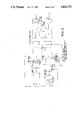
- FIG. 1 a system 10 embodying the invention is shown generally with the top plate removed.
- a return connector may be field installed in the top, bottom, side or end (as shown) to match the configuration of a field-installed air distribution system. That is, the system of the invention is adapted to be used with and/or incorporated into the ducts of existing air distribution systems. These prior art air distribution systems are configured to discharge air into a defined environment such as a natatorium. The discharged air, at least in part, contacts the surfaces where moisture accumulates and removes the moisture on a continual basis.
- the system of the invention may be installed with its own air distribution system or installed in an existing air distribution system. In either event with the inventive system the moisture is continuously, not continually, removed.
- Indoor airflow is established by drawing moisture-laden air from the room into a return plenum 12 through a return connector 14. Air then passes through a filter bank 16 before flowing into the intake side 18 of a return fan 20. Air is discharged from the return fan outlet 22 pressurizing a return/exhaust plenum 24.
- the fan 20 is controlled to run at a fixed speed.
- a bypass pressure sensor PS1 see FIG. 2, such as a Barber Coleman PP8516 with AD8501 reset module, measures the static pressure across downstream side of the fan 20 and upstream side of a supply fan 48 and this sensor PS1 actuates a motor driven bypass damper 26.
- the signal from the AD8501 is transmitted to a Barber Coleman MP5430 hydraulic actuator which drives the damper 26 between its open and closed position.
- a heat recovery module 30 has an exhaust side 32 and an intake side 34. Based on the position of an exhaust damper 36 a portion of the return air from the plenum 24 flows through the exhaust side 32 of the heat recovery module 30 and then to ambient through an exhaust connector 38.
- the remaining portion of the return air passes from plenum 24 through the bypass damper 26 into a common plenum 40.
- the intake side 34 of the heat recovery module 30 is in fluid flow communication with the plenum 40.
- An intake damper 42 is interposed between the intake side 34 and the plenum 40.
- the heat recovery module 30 is a TRU 120 Series energy recovery module as manufactured by QDT Ltd., Dallas, Texas.
- bypassed return air from plenum 24 and the intake air from ambient are mixed in the plenum 40.
- the mixed air in the plenum 40 passes through a heater coil 50 which adds enough heat to compensate for both the room heating requirement and the balance of the intake air reheat required after heat recovery.
- a Barber Coleman VB9323 3-way water diverting valve, V modulates the flow of hot water through a hydronic heating coil (not shown).
- the valve is operated by a Barber Coleman MP5410 hydraulic actuator according to a TS-8201-105 temperature sensor, T, see FIG. 2, mounted in the return/exhaust plenum 24; and a CP-8112 2-temperature input controller mounted in a control cabinet 52.
- the heated air passes from the heater coil 50 to the intake 54 of the supply fan 48. This air is then discharged from the supply fan outlet pressurizing a supply plenum 56.
- the air then flows to the field-installed air distribution system (not shown) through a supply connector 58 at a constant rate.
- the supply connector may be field installed in the top, bottom, side or end (as shown) to match configuration of field installed air distribution system.
- the humidity sensor/transmitter/controller combination may operate only exhaust damper 36 while a remote room static pressure controller, Dwyer 1640-0, PS2, a Dussault Engineering interface circuit (shown in FIG. FIG. 6) and a Barber Coleman AD-8501 reset module located in the control cabinet 52 operates the intake damper 42, as will be described.
- bypass damper 26 In all normal modes of operation, (except the refrigeration mode to be described) the bypass damper 26 is positioned by the differential static pressure sensor/controller PS1 previously described. This Barber Coleman PP-8516 senses the pressure differential between return/exhaust plenum 24 and common plenum 40 and via the AD8501 reset module operates the bypass damper.
- Outdoor air exchanged through exhaust connection 38 and an intake connection 44 is continuously variable from 0-100% of the system's nominal air flow depending on the indoor humidity demand and dryness of the available outside air.
- the system 10 is incorporated into an existing air distribution system of a natatorium.
- the defined environment will be maintained at a negative pressure with respect to the outdoors/surrounding occupied area.
- the nominal indoor air flow rate of 4800 CFM is to be established for proper wiping of condensation-prone indoor surfaces. It may be assumed that to produce the desired negative pressure return air volume will need exceed the supply air volume by 100 CFM. That is, there will be 100 CFM more air volume evacuated from the natatorium space than returned to it through the supply duct system.
- the desired indoor humidity and temperature levels to be maintained are 85° F. and 50% Relative Humidity.
- the desired temperature and humidity inputs are selected on the control panel.
- the nominal moisture loading by the pool is more or less fixed at 40 lbs. per hour. For this example, the beginning operating point for an outdoor condition of 20° F. and 95% R.H. would be selected.
- the 4800 CFM return air flow will be split; 900 CFM of exhaust to the outdoors and 3900 CFM bypassing to the supply/intake plenum.
- This 3900 CFM bypass air flow will combine with an 800 CFM flow of intake air to create the 4700 CFM supply air flow.
- the return/exhaust air flow versus the supply/intake air flow differ by 100 CFM to create the negative static pressure within the defined environment.
- the exhaust damper 36 is positioned to allow a 900 CFM exhaust air flow rate.
- the room negative pressure sensor/controller PS2, FIG. 3, senses the differential pressure between the natatorium space and the surrounding areas, and adjusts the intake air damper 42 to allow an 800 CFM intake air flow.
- the return/supply bypass pressure sensor PS1 senses the pressure differential between return/exhaust plenum 24 and supply/intake plenum 40 and positions the bypass damper 24 using the fan performance data on the supply and the return fans used. For this example a pressure differential of 2" W.C. is necessary to fix the return/supply air flow at the proper 4800 CFM nominal air flow rating.
- the humidity controller will reposition the exhaust damper 36 to allow a greater air flow than was previously required at the 20° F. level.
- the desired negative room pressure will be upset.
- the room negative pressure sensor/controller PS2 senses this shift in the room static pressure and in turn repositions intake damper 42 to bring the exhaust/intake air flow balance to the proper level to create the desired static pressure condition.
- the humidity controller opens the exhaust air damper 36 and in turn the room negative pressure sensor/controller follows opening the intake air damper 42, the pressure differential between return/exhaust plenum 24 and supply/intake plenum 40 is changed, upsetting the nominal air flow of the indoor loop.
- the return/supply bypass pressure sensor PS1 senses the pressure change caused by the exhaust/intake dampers 36/42, the bypass damper 26 is adjusted by the return/supply pressure controller to maintain the proper indoor air flow.
- the 4800 CFM of return is split with 1000 CFM discharging through the exhaust to the outside, 3800 CFM passing through the bypass damper.
- This 3800 CFM bypass air is mixed with the 900 CFM of intake air to produce the 4700 CFM supply air flow. Noting that there is still the desired 100 CFM differential between the return/exhaust air flow and the supply/intake air flow creating the desired negative pressure within the defined space.
- room temperature is sensed in the same return/exhaust plenum 24.
- the temperature controller T repositions the 3-way diverting valve V which supplies the hydronic heating coil in a typical unit.
- a similar control scheme may be applied to alternate forms of reheat, such as electric, steam, or other.
- an external boiler is required to supply either hot water or steam to the basic reheat coil.
- This process of varying the outdoor exchange rate while maintaining a constant indoor air flow is fully modulating from the minimum position, which would be 100 CFM exhaust, 0 CFM intake air, with 4700 CFM bypassed directly from the return/exhaust plenum 24 to the supply/intake plenum 40.
- This minimum position would be approached as the outdoor temperature dropped to very low levels and in turn the moisture content within that air dropped in a corresponding manner.
- the high end air flow parameters as the outdoor air temperature increases along with the outdoor humidity condition would by 0 CFM bypass from the return/exhaust plenum 24 to the supply/intake plenum 40 with 4800 CFM of air being discharged directly through the exhaust damper and heat recovery module to the outdoors and 4700 CFM of air being drawn through the intake filters heat recovery module and damper section to be discharged.
- the control system of the preferred embodiment is modified so that the humidity controller operates only the exhaust air damper.
- the supplemental room static pressure controller PC2 senses the change and readjusts the intake air damper 42 so that a predetermined room negative pressure condition is maintained.
- the humidity controller H changes the position of the exhaust damper 36
- the pressure controller PC2 "follows” the changes and repositions the intake damper 42.
- the bypass static pressure controller PC1 in turn "follows" the combined action of the exhaust/intake dampers holding the indoor airflow constant.
- the heat recovery module 30 used in the system is a bi-directional heat transfer device. Heat may be transferred from the exhaust air stream to the incoming air stream when intake air reheat is desired or from the intake air to the exhaust air stream when heat removal (cooling) is desired.
- the parameter which determines the direction of flow is temperature differential. Heat flows from the higher temperature face to the lower temperature face within the heat recovery module.
- supplemental components required to depress the face temperature of the exhaust side of the heat recovery module low enough for a significant cooling effect on the intake air are a water spray nozzle 60, pump 62 and a sump 64.
- a fine mist of water is sprayed on the exhaust face of the heat transfer module causing "evaporative cooling" to take place.
- the evaporation of the water from the exhaust face of the heat recovery unit cools the face creating a temperature differential with respect to the intake face required to draw heat from the hot incoming air and transfer it to the exhaust air.
- the spray pump 62 is cycled on and off and therefore, the cooling effect is also turned on and off.
- the cycling of the water spray mechanism is controlled by the same temperature/sensor control T which operates the reheat coil 50.
- the water spray is discharged between the exhaust damper and the exhaust face of the heat recovery module.
- This feature allows cooling in many applications without the electrical requirements, operating cost, and maintenance complications associated with compressor bearing refrigeration equipment.
- two plenums 70 and 72 are joined to the exhaust and intake air connections 38 and 44 respectively of the unit.
- a refrigeration coil 74 and a shut-off damper 76 are mounted in series between these plenums 70 and 72 so that when the refrigeration coil damper 76 is open the exhaust air bypasses through the refrigeration coil 74.
- Final exhaust/intake dampers 78 and 80 respectively are installed in each of these plenums at the connections to the final outside air ductwork.
- the system may operate as described in the preferred embodiment.
- the refrigeration coil damper 76 is closed and the final exhaust/intake dampers are opened. No air passes through the refrigeration coil and outside air flow is modulated in the usual fashion.
- Operation in the mode of the preferred embodiment continues until the incoming outdoor air no longer is dry enough to satisfy the indoor moisture load.
- the "summer dehumidification mode" is initiated based on the reading from the humidity/sensor control H.
- the final exhaust and intake dampers 78 and 80 are simultaneously closed.
- the refrigeration coil bypass damper 76 is opened and the refrigeration coil 74 is energized.
- normal operation of the intake, exhaust and bypass dampers is overridden.
- the bypass damper 26 is driven shut while control of the intake/exhaust dampers is switched to the bypass pressure controller PS1 which previously controlled the return/supply bypass damper (in winter mode).
- the modified air flow path is as follows. All of the return air is drawn through the return air fan and discharged through the exhaust damper. After passing through the damper the air passes through the "exhaust" side 32 of the heat recovery module 30, through the refrigeration coil 76 and damper 74 then directly back through the intake side 34 of the heat recovery module 30. From the heat recovery module the air flows through the intake face damper 42 and the intake/supply plenum to the reheat coil 50. Finally, the air is drawn through the supply fan 48 and discharged back to the defined environment.
- the bypass pressure sensor/controller operates the exhaust/intake face damper while the bypass damper is driven closed.
- the exhaust/intake damper positions are regulated so that the total static pressure produced by the air passing in series through the exhaust face damper, exhaust side of the heat recovery module, the refrigeration coil, the intake side of the heat recovery module and intake face damper matches the predetermined fixed setting (as determined by fan performance curves as described for the preferred embodiment). Again the total pressure from the return/exhaust plenum to the supply/intake plenum must be held constant to hold the indoor air flow constant.
- the power utilized in operating a refrigeration coil is spent doing two tasks: (1) Cooling the air (sensible cooling) and (2) Drying the air (latent cooling).
- refrigeration coils exhibit a sensible/latent split, as it is called, of 80%/20%. This means that 80% of the horsepower used to run the refrigeration unit is spent cooling the air and only 20% of the horsepower is dissipated cooling the air and only 20% of the horsepower is dissipated removing moisture. Using a refrigeration unit with such a sensible/latent split for moisture removal as its primary function is inefficient.
- This sensible/latent split can be affected by the condition of the air entering the refrigeration coil. If the relative humidity of the air entering the refrigeration coil can be shifted upwardly the sensible/latent split will in turn shift toward more latent heat removal.
- This embodiment of the invention uses the run around configuration of the heat recovery module to precondition the return air to approach 100% R.H. before entering the refrigeration coil.
- the limited amount of sensible cooling produced by the refrigeration coil at the intake side of the heat recovery module is transferred across to the exhaust side of the heat recovery module to pre-cool the return air before it enters the cooling coil.
- a heat pipe heat exchanger utilizes a series of refrigerant-charged tubes built into a coil such that a partition directs intake and exhaust air streams so that each is in contact with one half (lengthwise) of the tubes respectively.
- Refrigerant is "boiled" from the liquid state on the warm air side migrates across the exhaust/intake partition and condenses in the cold air side of the heat pipe releasing the heat energy in this transfer process. Since the condensed liquid refrigerant must drain back to the warm air side the transfer process is effected by the tilt angle of the heat pipe tubes.
- a steeper tilt angle makes the draining easier and in turn makes the heat transfer process more efficient. This characteristic of tilt vs. efficiency can be utilized to control how much heat is transferred from one air stream to the other.
- the return air relative humidity is shifted upwards by the pre-cooling effect across the heat transfer module.
- the pre-cooling effect can be adjusted so that the relative humidity of the air entering the refrigeration coil in turn can be controlled.
- the relative humidity is varied from the original return condition to the saturated level (100% relative humidity) the sensible output of the cooling coil will in turn be varied between its maximum and minimum levels.
- a heat pipe is used in conjunction with refrigeration coil.
Abstract
A temperature and humidity control system for natatoriums. The system provides a constant volume of air circulation which is used to control temperature and humidity in the natatorium while inhibiting the accumulation of moisture on the surfaces defining the natatorium. Usually, ambient air is introduced into the system and moisture latent air discharged from the system under controlled conditions. When the humidity of the ambient air is too great the system operates in a self-contained cycle. Return air from the natatorium flowing through the system is treated to maximize its relative humidity. Subsequently, it flows across a cooling coil. This cooled air flows through a heat exchange module where it is placed in exchange relationship with the air being drawn from the natatorium. It cools the air drawn from the natatorium to maximize its relative humidity and this air in turn flows across the refrigeration coil removing substantial quantities of moisture. Combining the refrigeration coil with the heat transfer module and the other components in the system, the sensible/latent heat split is shifted towards higher latent output increasing the overall efficiency of the system as a dehumidification device.
Description
This invention relates to an apparatus and method for improving ventilation in the form of humidity and temperature control especially when applied to the control of moisture in indoor swimming pool environments (natatoriums).
Natatoriums are typically operated at high humidity levels as compared to standard living space to provide creature comfort to wet-bodied inhabitants. This high humidity level (dew point) creates condensation on the surfaces of building components. In addition to being disagreeable aesthetically, the constant presence of condensation promotes the growth of mildew and fungi and may greatly accelerate deterioration of both surface and internal building components.
Natatoriums place two specific demands on a high volume air conditioning (HVAC) system which are unqiue: the system must remove a relatively constant amount of moisture which migrates into the air by evaporation of the pool surface; and
the air system must be equipped to deliver a constant supply of warm/dry air which can be directed toward condensation-prone building components, such as windows.
Humidity control has typically been attempted by implementing standard ventilation systems. In these systems, exhaust/intake fans may be cycled on and off either manually or by "make/break" humidity controllers. This same general approach can be combined with space heating equipment in the form of direct or indirect fired make-up-air systems. Electric, hydronic or steam heaters may also be employed as heat source in make-up-air equipment.
Both versions of the straight ventilation approach to humidity control have serious drawbacks. Because the blowers are either on or off, great swings in humidity and temperature conditions result, especially when both heat and outside air are delivered through the same on/off make-up-air unit. During colder weather the heating demands of the pool space will cause the standard make-up-air system to run longer than would be required to satisfy the moisture removal requirement in order to produce adequate heat. The surplus of outside air causes the humidity level within the pool environment to drop below the comfort level. Even though the heater may keep the air temperature at 80 degrees or more when the relative humidity drops much below 50-60% relative humidity evaporation on the skin of wet bodies using the pool results in the sensation of being cold. This condition may be expected when the relative humidity level drops much below the 50-60% level.
The standard ventilation systems as described above do not have the ability to provide a continuous supply of air to windows and other condensation-prone surfaces. When the system is "on" the airflow is available to "wipe" these surfaces. Between cycles when the system is "off" the airflow ceases and immediately condensation begins to form on susceptible surfaces.
If the fans are kept in operation continuously to establish the desired constant air flow, wide temperature swings will result. In addition this continuous air exchange will drive the relative humidity to extremely low and uncomfortable levels.
One of the worst drawbacks of the standard ventilation systems is the operating cost. Heating 100% make-up-air, especially in colder climates, is completely unacceptable in light of high utility costs.
Some attempts have been made to address the humidity and temperature control requirements of indoor swimming pools with mechanical refrigeration or heat pump equipment. These systems remove moisture by circulating air from the natatorium through a chilled coil whereby water is condensed out of the air stream before it is introduced back into the defined indoor space. These systems typically produce the same fluctuations in temperature and humidity because the method of control is "make/break". There is often a conflict in the operational modes of the heat pump where adequate dehumidification and heat output can not be derived at the same time (so the air becomes either too cold or too wet). Finally these compressor-bearing units require substantial electrical branch circuits to accommodate their relatively large draw of power.
The invention utilizes the simplicity of standard ventilation equipment in that few moving parts are required for operation. The only significant moving parts required for basic operation are two fans and a series of motorized dampers. This does not include the reheat section which may incorporate one of many types of heating sources (hydronic, electric, steam, gas or oil) and may rely on a remote source of heat such as a boiler.
The invention eliminates the temperature and humidity swings typical of any of the "make/break" systems by full modulation of the outdoor air intake/exhaust for humidity control and with full modulation of the reheat coil output.
By incorporating the energy recovery module into the exhaust/intake section of the system, most of the enormous cost of heating outside intake air may be saved.
Because the only significant electrical consumption by the invention is by its two fans, electrical requirements are greatly reduced as compared to compressor bearing refrigeration devices. This does not include the reheat coil which may be electric and therefore would increase the electrical requirement, however, space heating demand due to transmission loss on this coil would be virtually identical in any of the systems described.
The power consumed by the invention to effect the dehumidification process is substantially less than both the ventilation-type systems and the refrigeration-type systems because of the relatively low power requirement of the fan systems and the high efficiency energy recovery module.
Because of the limited number of moving parts and use of electronic controls the invention is reliable with a lower long-term cost of maintenance when compared to compressor bearing refrigeration units. Regular preventative maintenance consists of air filter maintenance and occasional lubrication of fan parts.
The present invention embodies a system and a method of controlling the moisture accumulation, the relative humidity and the temperature in a defined environment such as a natatorium. The moisture removal is effected by exchanging a variable amount of moisture-laden air for drier outdoor (ambient) air. The volume of air required is variable because the dryness of the outdoor air is variable. As the outdoor air gets drier the volume of air exchange required to compensate for the constant pool evaporation is reduced.
Constant indoor airflow which continuously wipes those surfaces prone to moisture accumulation is achieved by integrating the flow of outdoor air with the indoor air and discharging the same at a constant flow rate.
The flow of the outdoor air is modulated, based on the indoor humidity demand and the dryness of the outdoor air to ensure the indoor airflow remains at a constant level.
In a preferred embodiment of the invention, a modulating humidity/sensor control senses the indoor humidity condition and opens/closes exhaust/intake dampers until the humidity condition reaches the setpoint as selected at the humidity control. The exhaust damper is on the pressure-side (downstream) of a return fan which removes the moisture laden air from the environment. Also on the pressure side of the fan is a bypass damper through which flows the moisture laden air not discharged through the exhaust damper.
The intake damper is on the suction-side (upstream) of a supply fan. The intake damper controls the amount of outdoor air entering the system. The outside air and the moisture laden air flowing through the bypass damper are combined in a common plenum in which plenum is disposed a reheat coil on the suction side of the supply fan. This supply fan discharges the air back into the defined environment.
To maintain the indoor airflow through the return/supply loop constant, the fundamental characteristics of centrifugal blowers are applied. For a blower operating at a fixed speed (R.P.M.), the volume of air passing through the blower will be constant for a given static pressure loading across the blower inlet/discharge. That is, if the static pressure across the blowers is controlled at a constant level the airflow through the blower will also be constant.
A sensor reads the pressure differential across the blowers (bypass damper) and operates the bypass damper actuator open/closed to maintain the fixed static pressure reading (as determined by the fan performance curves).
The modulation of the face exhaust/intake dampers would normally tend to build/relieve the static pressure across the bypass damper, which would change the indoor airflow. However, the bypass damper pressure control "follows" the action of the intake and exhaust dampers holding the differential pressure and in turn the indoor airflow is held constant.
During this process heat energy is transferred from the exhaust air to the intake air by using a heat recovery device. This heat recovery minimizes the reheat necessary to bring the incoming dry air up to room temperature.
A reheat coil adds heat to the air in the common plenum to compensate for the space heating requirements as well as to reheat the incoming dry air.
Another desirable feature for indoor pool applications is to maintain the overall static pressure in the defined environment slightly negative with respect to the surrounding living spaces and outdoors. With this slight negative pressure the high-moisture content air is confined better within the natatorium. With a null or positive pressure, moisture tends to migrate outwardly into the surrounding living spaces as well as into building components where it can do damage.
In one alternative embodiment of the invention, a supplemental room static pressure sensor/control is used to ensure a predetermined room negative pressure is maintained. In this alternative embodiment, the exhaust and intake dampers are controlled independently.
As determined by certain design conditions some cooling may be required to maintain the defined environment at acceptable levels. That is, in some circumstances the outside air being drawn into the system may be at a higher temperature than the desired temperature within the room. Therefore, in another embodiment of the invention, by adding supplemental components to the system of the preferred embodiment, cooling of the incoming outside air may be accomplished without using traditional compressor driven mechanical refrigeration equipment.
In the previously described preferred embodiment, the invention relies on the dryness of the outside air to drive the dehumidification process. The system is most effective during dry winter months and/or in areas with relatively dry year-round climates.
In applications where the summertime outside humidity level approaches or exceeds the desired indoor humidity level, humidity control by ventilation becomes impractical, air exchange volumes become excessive. Installation and operating cost, because of increased equipment sizing, is also increased. In addition the required high indoor air flow required may cause noise and discomfort due to turbulence and drafts.
For climates where these conditions are encountered, in still another embodiment of the invention, mechanical refrigeration equipment is integrated into the system in a manner to maximize comfort and minimize energy consumption in all operational modes. Broadly, a refrigeration coil/damper module is combined with the system of the preferred embodiment. This module is joined at the outside air connections of the invention.
FIG. 1 is a plan view of a system embodying the invention;
FIG. 2 is a schematic of the preferred embodiment;
FIG. 3 is a schematic of the first alternative embodiment;
FIG. 4 is a schematic of the second alternative embodiment;
FIG. 5 is a schematic of the third alternative embodiment; and
FIGS. 6a, 6b and 6c are schematics of the controls of the complete system.
Referring to the FIG. 1, a system 10 embodying the invention is shown generally with the top plate removed.
A return connector may be field installed in the top, bottom, side or end (as shown) to match the configuration of a field-installed air distribution system. That is, the system of the invention is adapted to be used with and/or incorporated into the ducts of existing air distribution systems. These prior art air distribution systems are configured to discharge air into a defined environment such as a natatorium. The discharged air, at least in part, contacts the surfaces where moisture accumulates and removes the moisture on a continual basis. The system of the invention may be installed with its own air distribution system or installed in an existing air distribution system. In either event with the inventive system the moisture is continuously, not continually, removed.
Indoor airflow is established by drawing moisture-laden air from the room into a return plenum 12 through a return connector 14. Air then passes through a filter bank 16 before flowing into the intake side 18 of a return fan 20. Air is discharged from the return fan outlet 22 pressurizing a return/exhaust plenum 24.
In this preferred embodiment, the fan 20 is controlled to run at a fixed speed. A bypass pressure sensor PS1 see FIG. 2, such as a Barber Coleman PP8516 with AD8501 reset module, measures the static pressure across downstream side of the fan 20 and upstream side of a supply fan 48 and this sensor PS1 actuates a motor driven bypass damper 26. Specifically, the signal from the AD8501 is transmitted to a Barber Coleman MP5430 hydraulic actuator which drives the damper 26 between its open and closed position.
A heat recovery module 30 has an exhaust side 32 and an intake side 34. Based on the position of an exhaust damper 36 a portion of the return air from the plenum 24 flows through the exhaust side 32 of the heat recovery module 30 and then to ambient through an exhaust connector 38.
The remaining portion of the return air passes from plenum 24 through the bypass damper 26 into a common plenum 40.
The intake side 34 of the heat recovery module 30 is in fluid flow communication with the plenum 40. An intake damper 42 is interposed between the intake side 34 and the plenum 40.
Based on the position of the intake damper 42 an amount of outside air is drawn through an outside air intake connector 44, an intake filter bank 46, the heat recovery module intake side 34 and into the common plenum 40 through the intake damper 42.
The heat recovery module 30 is a TRU 120 Series energy recovery module as manufactured by QDT Ltd., Dallas, Texas.
The bypassed return air from plenum 24 and the intake air from ambient are mixed in the plenum 40.
The mixed air in the plenum 40 passes through a heater coil 50 which adds enough heat to compensate for both the room heating requirement and the balance of the intake air reheat required after heat recovery.
In the preferred embodiment, a Barber Coleman VB9323 3-way water diverting valve, V, see FIG. 2, modulates the flow of hot water through a hydronic heating coil (not shown). The valve is operated by a Barber Coleman MP5410 hydraulic actuator according to a TS-8201-105 temperature sensor, T, see FIG. 2, mounted in the return/exhaust plenum 24; and a CP-8112 2-temperature input controller mounted in a control cabinet 52.
The heated air passes from the heater coil 50 to the intake 54 of the supply fan 48. This air is then discharged from the supply fan outlet pressurizing a supply plenum 56.
The air then flows to the field-installed air distribution system (not shown) through a supply connector 58 at a constant rate. The supply connector may be field installed in the top, bottom, side or end (as shown) to match configuration of field installed air distribution system.
A Barber Coleman AH102 humidity sensor H see, FIG. 2, is mounted in the return/exhaust plenum 24. It is used in combination with a HS8201 humidity transmitter and a CP8112 2-input controller mounted in the control cabinet 52. This combination controls a MP5430 intake/exhaust damper actuator which drives the dampers 36 and 42 open/closed according to humidity demand. These dampers, the intake damper 42 and the exhaust damper 36, may be linked for operation together based on humidity demand alone if negative room static pressure control is not desired. Where negative room static pressure is desired the humidity sensor/transmitter/controller combination (AH-102, HS8201, CP8112) may operate only exhaust damper 36 while a remote room static pressure controller, Dwyer 1640-0, PS2, a Dussault Engineering interface circuit (shown in FIG. FIG. 6) and a Barber Coleman AD-8501 reset module located in the control cabinet 52 operates the intake damper 42, as will be described.
In all normal modes of operation, (except the refrigeration mode to be described) the bypass damper 26 is positioned by the differential static pressure sensor/controller PS1 previously described. This Barber Coleman PP-8516 senses the pressure differential between return/exhaust plenum 24 and common plenum 40 and via the AD8501 reset module operates the bypass damper.
Since the static pressure exhibited in the supply and return air distribution system is fixed for a given air flow, maintaining a constant pressure differential between return/exhaust plenum 24 and the common plenum 40 creates a constant indoor air volume.
Outdoor air exchanged through exhaust connection 38 and an intake connection 44 is continuously variable from 0-100% of the system's nominal air flow depending on the indoor humidity demand and dryness of the available outside air.
At any intake/exhaust damper 42/36 position the indoor airflow is held constant by positioning the bypass damper 26 to maintain the static pressure across return fan 20 and supply fan 48 constant.
The operation of the invention will be explained in reference to the following non-limiting illustrative example.
The system 10 is incorporated into an existing air distribution system of a natatorium. The defined environment will be maintained at a negative pressure with respect to the outdoors/surrounding occupied area. The nominal indoor air flow rate of 4800 CFM is to be established for proper wiping of condensation-prone indoor surfaces. It may be assumed that to produce the desired negative pressure return air volume will need exceed the supply air volume by 100 CFM. That is, there will be 100 CFM more air volume evacuated from the natatorium space than returned to it through the supply duct system.
The desired indoor humidity and temperature levels to be maintained are 85° F. and 50% Relative Humidity. The desired temperature and humidity inputs are selected on the control panel. The nominal moisture loading by the pool is more or less fixed at 40 lbs. per hour. For this example, the beginning operating point for an outdoor condition of 20° F. and 95% R.H. would be selected.
At this operating condition and air exchange rate of 900 CFM exhaust and 800 CFM of intake air will be required to dissipate the 40 lb. per hour moisture load. At the steady state condition the air flow rates will be as follows:
______________________________________
Return air volume: 4800 CFM
Supply air volume: 4700 CFM
Exhaust air:        900 CFM
Intake air:         800 CFM
Supply/return bypass air:
                   3900 CFM
______________________________________
In this steady state condition, the 4800 CFM return air flow will be split; 900 CFM of exhaust to the outdoors and 3900 CFM bypassing to the supply/intake plenum. This 3900 CFM bypass air flow will combine with an 800 CFM flow of intake air to create the 4700 CFM supply air flow. Again, the return/exhaust air flow versus the supply/intake air flow differ by 100 CFM to create the negative static pressure within the defined environment.
Based on the percent humidity sensed in return/exhaust plenum 24, the exhaust damper 36 is positioned to allow a 900 CFM exhaust air flow rate. The room negative pressure sensor/controller PS2, FIG. 3, senses the differential pressure between the natatorium space and the surrounding areas, and adjusts the intake air damper 42 to allow an 800 CFM intake air flow. The return/supply bypass pressure sensor PS1 senses the pressure differential between return/exhaust plenum 24 and supply/intake plenum 40 and positions the bypass damper 24 using the fan performance data on the supply and the return fans used. For this example a pressure differential of 2" W.C. is necessary to fix the return/supply air flow at the proper 4800 CFM nominal air flow rating.
From this steady state operating condition at 20° F. and 95% relative humidity outdoor conditions, assume that the outdoor conditions now change to 30° F. and 95% relative humidity, the moisture content is now approximately 60% higher than at 20° F. and 95% relative humidity. At this new condition the more humid air has less capacity for drying the indoor air space, so at the steady state damper position for 20° F. and 95% relative humidity bringing in this higher humidity air will cause the moisture condition to drift to a higher level than the desired 50% relative humidity.
Immediately upon an upward drift in the humidity condition as sensed by the humidity sensor H in return/exhaust plenum 24 the humidity controller will reposition the exhaust damper 36 to allow a greater air flow than was previously required at the 20° F. level. As exhaust damper 36 starts to open evacuating more air than the previous steady state condition, the desired negative room pressure will be upset. As the exhaust air flow begins to increase, while the intake air flow is held at the original 800 CFM level, the pressure differential between the natatorium space and surrounding areas begins to increase beyond the preset value. The room negative pressure sensor/controller PS2 senses this shift in the room static pressure and in turn repositions intake damper 42 to bring the exhaust/intake air flow balance to the proper level to create the desired static pressure condition. As the humidity controller opens the exhaust air damper 36 and in turn the room negative pressure sensor/controller follows opening the intake air damper 42, the pressure differential between return/exhaust plenum 24 and supply/intake plenum 40 is changed, upsetting the nominal air flow of the indoor loop. When the return/supply bypass pressure sensor PS1 senses the pressure change caused by the exhaust/intake dampers 36/42, the bypass damper 26 is adjusted by the return/supply pressure controller to maintain the proper indoor air flow.
As the outdoor condition shifts from 20° F. and 95% relative humidity to 30° F. and 95% R.H., the values for the system air flows will be modified as follows:
______________________________________
Return air flow:    4800 CFM
Exhaust air flow:   1000 CFM
Supply air flow:    4700 CFM
Intake air flow:     900 CFM
Return/supply bypass air flow:
                    3800 CFM
______________________________________
Under this new steady state condition the 4800 CFM of return is split with 1000 CFM discharging through the exhaust to the outside, 3800 CFM passing through the bypass damper. This 3800 CFM bypass air is mixed with the 900 CFM of intake air to produce the 4700 CFM supply air flow. Noting that there is still the desired 100 CFM differential between the return/exhaust air flow and the supply/intake air flow creating the desired negative pressure within the defined space.
Independent of the humidity control, room temperature is sensed in the same return/exhaust plenum 24. As the room temperature has a tendency to drift upwards or downwards in response to higher or lower building heating loss and/or changes in the amount of outside air which must be reheated to room condition, the temperature controller T repositions the 3-way diverting valve V which supplies the hydronic heating coil in a typical unit. A similar control scheme may be applied to alternate forms of reheat, such as electric, steam, or other. Typically, an external boiler is required to supply either hot water or steam to the basic reheat coil.
This process of varying the outdoor exchange rate while maintaining a constant indoor air flow is fully modulating from the minimum position, which would be 100 CFM exhaust, 0 CFM intake air, with 4700 CFM bypassed directly from the return/exhaust plenum 24 to the supply/intake plenum 40. This minimum position would be approached as the outdoor temperature dropped to very low levels and in turn the moisture content within that air dropped in a corresponding manner.
The high end air flow parameters as the outdoor air temperature increases along with the outdoor humidity condition would by 0 CFM bypass from the return/exhaust plenum 24 to the supply/intake plenum 40 with 4800 CFM of air being discharged directly through the exhaust damper and heat recovery module to the outdoors and 4700 CFM of air being drawn through the intake filters heat recovery module and damper section to be discharged.
Referring to FIG. 3, in one alternative embodiment of the invention, the control system of the preferred embodiment is modified so that the humidity controller operates only the exhaust air damper. When the exhaust air damper 36 is modulated by itself there is a tendency to evacuate or pressurize the room. The supplemental room static pressure controller PC2 senses the change and readjusts the intake air damper 42 so that a predetermined room negative pressure condition is maintained. When the humidity controller H changes the position of the exhaust damper 36, the pressure controller PC2 "follows" the changes and repositions the intake damper 42. The bypass static pressure controller PC1 in turn "follows" the combined action of the exhaust/intake dampers holding the indoor airflow constant.
The heat recovery module 30 used in the system is a bi-directional heat transfer device. Heat may be transferred from the exhaust air stream to the incoming air stream when intake air reheat is desired or from the intake air to the exhaust air stream when heat removal (cooling) is desired. The parameter which determines the direction of flow is temperature differential. Heat flows from the higher temperature face to the lower temperature face within the heat recovery module.
Under summer operating conditions, without supplemental components it is difficult to remove heat from the outside air since the 80 or 90 degree incoming air is almost at the same temperature as the 80 degree air exhausted. Little or no temperature difference results in little or no heat transfer transfer.
In another embodiment of the invention, referring to FIG. 4, supplemental components required to depress the face temperature of the exhaust side of the heat recovery module low enough for a significant cooling effect on the intake air are a water spray nozzle 60, pump 62 and a sump 64.
A fine mist of water is sprayed on the exhaust face of the heat transfer module causing "evaporative cooling" to take place. The evaporation of the water from the exhaust face of the heat recovery unit cools the face creating a temperature differential with respect to the intake face required to draw heat from the hot incoming air and transfer it to the exhaust air.
The spray pump 62 is cycled on and off and therefore, the cooling effect is also turned on and off. The cycling of the water spray mechanism is controlled by the same temperature/sensor control T which operates the reheat coil 50.
The water spray is discharged between the exhaust damper and the exhaust face of the heat recovery module.
This feature allows cooling in many applications without the electrical requirements, operating cost, and maintenance complications associated with compressor bearing refrigeration equipment.
Referring to FIGS. 1 and 5, in still another alternate embodiment, two plenums 70 and 72 are joined to the exhaust and intake air connections 38 and 44 respectively of the unit. A refrigeration coil 74 and a shut-off damper 76 are mounted in series between these plenums 70 and 72 so that when the refrigeration coil damper 76 is open the exhaust air bypasses through the refrigeration coil 74.
Final exhaust/ intake dampers 78 and 80 respectively are installed in each of these plenums at the connections to the final outside air ductwork.
In this embodiment the system may operate as described in the preferred embodiment. When the refrigeration coil damper 76 is closed and the final exhaust/intake dampers are opened. No air passes through the refrigeration coil and outside air flow is modulated in the usual fashion.
Operation in the mode of the preferred embodiment continues until the incoming outdoor air no longer is dry enough to satisfy the indoor moisture load.
At this point the "summer dehumidification mode" is initiated based on the reading from the humidity/sensor control H. In this mode the final exhaust and intake dampers 78 and 80 are simultaneously closed. The refrigeration coil bypass damper 76 is opened and the refrigeration coil 74 is energized. During this changeover sequence in the refrigeration module, normal operation of the intake, exhaust and bypass dampers is overridden.
The bypass damper 26 is driven shut while control of the intake/exhaust dampers is switched to the bypass pressure controller PS1 which previously controlled the return/supply bypass damper (in winter mode).
The modified air flow path is as follows. All of the return air is drawn through the return air fan and discharged through the exhaust damper. After passing through the damper the air passes through the "exhaust" side 32 of the heat recovery module 30, through the refrigeration coil 76 and damper 74 then directly back through the intake side 34 of the heat recovery module 30. From the heat recovery module the air flows through the intake face damper 42 and the intake/supply plenum to the reheat coil 50. Finally, the air is drawn through the supply fan 48 and discharged back to the defined environment.
This integration of the refrigeration coil with the module 30 results in a "run around" configuration where the same air flow passes through both sides of the heat recovery module.
The bypass pressure sensor/controller operates the exhaust/intake face damper while the bypass damper is driven closed. The exhaust/intake damper positions are regulated so that the total static pressure produced by the air passing in series through the exhaust face damper, exhaust side of the heat recovery module, the refrigeration coil, the intake side of the heat recovery module and intake face damper matches the predetermined fixed setting (as determined by fan performance curves as described for the preferred embodiment). Again the total pressure from the return/exhaust plenum to the supply/intake plenum must be held constant to hold the indoor air flow constant.
This run around configuration causes the refrigeration coil to act as a more efficient moisture removal device than can be obtained without the heat transfer module.
The power utilized in operating a refrigeration coil is spent doing two tasks: (1) Cooling the air (sensible cooling) and (2) Drying the air (latent cooling).
Typically refrigeration coils exhibit a sensible/latent split, as it is called, of 80%/20%. This means that 80% of the horsepower used to run the refrigeration unit is spent cooling the air and only 20% of the horsepower is dissipated cooling the air and only 20% of the horsepower is dissipated removing moisture. Using a refrigeration unit with such a sensible/latent split for moisture removal as its primary function is inefficient.
Eighty percent of the power used to operate the machine is essentially wasted performing unwanted cooling while only 20% is directed toward the useful work of moisture removal.
This sensible/latent split can be affected by the condition of the air entering the refrigeration coil. If the relative humidity of the air entering the refrigeration coil can be shifted upwardly the sensible/latent split will in turn shift toward more latent heat removal.
Because the return air coming from the pool space is normally only 50-60% R.H., the normal sensible/latent split will not change significantly.
If the return air entering the refrigeration coil were close to 100% R.H., the sensible/latent split would shift to almost all latent work and little sensible cooling.
This embodiment of the invention uses the run around configuration of the heat recovery module to precondition the return air to approach 100% R.H. before entering the refrigeration coil.
The limited amount of sensible cooling produced by the refrigeration coil at the intake side of the heat recovery module is transferred across to the exhaust side of the heat recovery module to pre-cool the return air before it enters the cooling coil.
During this pre-cooling process, the return air moisture content remains essentially the same, but because of the lower temperature the relative humidity shifts from the 50% or 60% level to almost 100% (saturated).
Now the saturated return air enters the cooling coil and the sensible/latent split exhibited by the coil will be more like 20%/80% respectively. This refrigeration/damper module offers peak efficiency and lower operating cost under all operating conditions.
When the outside air is dry enough the system reverts to the basic operational mode of dehumidification with ventilation using energy recovery. When the outside air becomes too moist to be useful for drying, the outside air is shut down. The "run around" refrigeration loop is employed with practically no power wasted on unwanted sensible cooling.
In a refined version of this "run around" configuration, manipulation of the heat recovery module results in the ability to adjust continuously the sensible/latent output ratio of the refrigeration coil.
Although the ability to operate the refrigeration coil at the maximum latent output possible may be desirable sometimes a variable amount of sensible cooling may be required to compensate for building heat gain (cooling load). This feature is attainable using a certain type of energy recovery device.
A heat pipe heat exchanger utilizes a series of refrigerant-charged tubes built into a coil such that a partition directs intake and exhaust air streams so that each is in contact with one half (lengthwise) of the tubes respectively.
Refrigerant is "boiled" from the liquid state on the warm air side migrates across the exhaust/intake partition and condenses in the cold air side of the heat pipe releasing the heat energy in this transfer process. Since the condensed liquid refrigerant must drain back to the warm air side the transfer process is effected by the tilt angle of the heat pipe tubes.
A steeper tilt angle makes the draining easier and in turn makes the heat transfer process more efficient. This characteristic of tilt vs. efficiency can be utilized to control how much heat is transferred from one air stream to the other.
In the run around configuration the return air relative humidity is shifted upwards by the pre-cooling effect across the heat transfer module. By varying the tilt angle of the energy recovery device with a motorized actuator the pre-cooling effect can be adjusted so that the relative humidity of the air entering the refrigeration coil in turn can be controlled. As the relative humidity is varied from the original return condition to the saturated level (100% relative humidity) the sensible output of the cooling coil will in turn be varied between its maximum and minimum levels. A heat pipe is used in conjunction with refrigeration coil.
Claims (23)
1. A system for providing a continuous flow of air to control surface condensation, humidity and temperture in a defined environment which comprises:
means to introduce return air into the system from the defined environment at a first humidity and first temperature; means to measure the humidity of said return air;
means disposed within the system to exhaust one portion of said return air to ambient;
means to recycle another portion of said return air;
means to flow through the system intake air, said intake air at a second humidity and a second temperature;
means to discharge continuously into the defined environment supply air at a third humidity and a third temprature;
a heat recovery module having an exhaust side through which the return air flows and an inlet side through which the intake air flows;
a refrigeration module having first and second zones, the first zone downstream of and in communication with the exhaust side of the heat recovery module, the second zone upstream of and in communication with the intake side of the heat recovery module, the second zone including means to cool the return air flowing therethrough;
means to control the flow of the return air from the first zone to the second zone to cool said return air;
means to flow said cooled recycled return air as intake air from the second zone through the intake side of the heat recovery module, said intake air in heat exchange relationship with the return air flowing through the exhaust side of the heat recovery module, to thereby cool the return air flowing through the exhaust side of the heat recovery module and to increase the relative humidity of said return air, which return air then flows through the second zone and means to control the flow rates of the return air and the intake air to discharge the supply air.
2. The system of claim 1 wherein the means to introduce the return air into the system comprises:
a return fan which removes the return air from the defined environment and the means to exhaust and recycle the return air comprises a return/exhaust plenum, said plenum including an exhaust damper and a bypass damper, the bypass damper in communication with the common plenum, the exhaust damper in communication with ambient.
3. The system of claim 2 wherein the means to introduce the intake air into the system comprises a supply fan and the common plenum further comprises an intake damper, said intake damper in communication with ambient and the supply fan.
4. The system of claim 3 wherein the means to control the flow rates comprises:
means to move variably the exhaust damper and the bypass damper between open and closed positions thereby controlling the flow rates of the exhaust air and the recycled return air, said exhaust damper responsive to the humidity of the return air and said bypass damper responsive to the static pressure across the return/exhaust plenum and the common plenum.
5. The system of claim 1 which comprises:
means to maintain the defined environment at a negative pressure with respect to ambient.
6. The system of claim 1 wherein the means to control the flow rates of the return air and the intake air comprises:
means to sense the static pressure loading across the means to introduce the return air and the means to introduce the intake air.
7. The system of claim 1 which comprises means to introduce intake air into the system from ambient.
8. The system of claim 1 which comprises means to combine intake air from ambient and the return air in a common plenum to form a combined air stream, the common plenum in fluid flow communication with the means to introduce the intake air and the means to recycle the return air.
9. The system of claim 1 wherein the means to cool the air in the second zone comprises a heat pipe heat exchanger.
10. The system of claim 1 which comprises means to flow all of the return air into the first zone and through the second zone.
11. The system of claim 1 which includes means to prevent introduction of ambient air into the system.
12. The system of claim 1 which comprises means to divert all of the air from the first zone into the second zone.
13. A method of controlling surface condensation, temperature and humidity in a defined environment which includes:
(a) flowing return air from the environment into a system at a first temperature and a first humidity;
(b) recyling as intake air at least a portion of the return air;
(c) flowing intake air through the system;
(d) placing dry cooled intake air in heat exchange relationship with the return air to increase the humidity of said return air;
(e) cooling subsequently the return air of step (d) in a cooling zone to remove moisture therefrom, said cooled return air forming at least part of the cooled dried intake air;
(f) controlling the flow rates of the intake air and the return air; and
(g) discharging said cooled dried intake air as supply air into the defined environment at a third humidity and third temperature.
14. The method of claim 13 which includes:
controlling the flow rates of the return air and the intake air based on the static pressure loading across he return air and the inake air.
15. The method of claim 14 which includes:
maintaining the pressure in the defined environment negative with respect to ambient.
16. The method of claim 15 which includes:
maintaining return air flow at a greater rate than the supply air flow.
17. The method of claim 14 which includes:
placing the combined air stream in heat exchange relationship with a heat exchange medium prior to discharging said stream into the defined environment.
18. The method of claim 13 which includes:
introducing intake air into the system from ambient.
19. The method of claim 18 which includes:
placing the return air discharged from the return/exhaust plenum in heat exchange relationship with the intake air prior to said intake air entering the common plenum.
20. The system of claim 19 which includes:
cooling said intake air.
21. The method of claim 13 wherein the system includes a common plenum and which further includes:
combining the intake air from ambient and the return air in the common plenum to form a combined air stream and to introduce said air stream into the defined environment as supply air.
22. The method of claim 13 which includes:
recycling all of said return air through the cooling zone;
23. The method of claim 22 which includes:
preventing the introduction of ambient intake air into the system.
Priority Applications (1)
| Application Number | Priority Date | Filing Date | Title |
|---|---|---|---|
| US07/141,630 US4841733A (en) | 1988-01-07 | 1988-01-07 | Dri-Pc humidity and temperature controller |
Applications Claiming Priority (1)
| Application Number | Priority Date | Filing Date | Title |
|---|---|---|---|
| US07/141,630 US4841733A (en) | 1988-01-07 | 1988-01-07 | Dri-Pc humidity and temperature controller |
Publications (1)
| Publication Number | Publication Date |
|---|---|
| US4841733A true US4841733A (en) | 1989-06-27 |
Family
ID=22496508
Family Applications (1)
| Application Number | Title | Priority Date | Filing Date |
|---|---|---|---|
| US07/141,630 Expired - Lifetime US4841733A (en) | 1988-01-07 | 1988-01-07 | Dri-Pc humidity and temperature controller |
Country Status (1)
| Country | Link |
|---|---|
| US (1) | US4841733A (en) |
Cited By (129)
| Publication number | Priority date | Publication date | Assignee | Title |
|---|---|---|---|---|
| US5024263A (en) * | 1987-12-18 | 1991-06-18 | Ilmatera Oy | Method and apparatus for the control of air flows and pressures in air-conditioning |
| US5058388A (en) * | 1989-08-30 | 1991-10-22 | Allan Shaw | Method and means of air conditioning |
| AU629030B2 (en) * | 1989-08-30 | 1992-09-24 | Luminis Pty Limited | Comfort integration and energy efficient method of air conditioning |
| US5249596A (en) * | 1992-03-06 | 1993-10-05 | Carrier Corporation | Residential heating and air conditioning barometric bypass damper |
| US5325676A (en) * | 1992-08-24 | 1994-07-05 | Milton Meckler | Desiccant assisted multi-use air pre-conditioner unit with system heat recovery capability |
| US5346129A (en) * | 1993-05-17 | 1994-09-13 | Honeywell Inc. | Indoor climate controller system adjusting both dry-bulb temperature and wet-bulb or dew point temperature in the enclosure |
| US5348077A (en) * | 1991-03-29 | 1994-09-20 | Hillman Chris F | Integrated air exchanger |
| WO1995028609A1 (en) * | 1992-08-24 | 1995-10-26 | Milton Meckler | Desiccant assisted multi-use air pre-conditioner unit with system heat recovery capability |
| US5461877A (en) * | 1991-05-24 | 1995-10-31 | Luminis Pty Ltd. | Air conditioning for humid climates |
| US5675979A (en) * | 1996-03-01 | 1997-10-14 | Honeywell Inc. | Enthalpy based thermal comfort controller |
| US5931376A (en) * | 1994-11-07 | 1999-08-03 | Luwa Ag | Device for air-conditioning control in an air-conditioned room having textile machines |
| US6012296A (en) * | 1997-08-28 | 2000-01-11 | Honeywell Inc. | Auctioneering temperature and humidity controller with reheat |
| US6016710A (en) * | 1998-02-11 | 2000-01-25 | Semco Incorporated | Method and apparatus for measuring the quantity of outdoor air processed by an air preconditioning module |
| WO2000011409A1 (en) * | 1998-08-25 | 2000-03-02 | Gas Research Institute | Dual mode air treatment apparatus and method |
| US6067808A (en) * | 1998-09-24 | 2000-05-30 | Ford Motor Company | Method of air conditioner operation for minimizing moisture condensed on evaporator core |
| US6209622B1 (en) * | 1994-10-24 | 2001-04-03 | Venmar Ventilation Inc. | Ventilation system |
| WO2001084066A1 (en) * | 2000-05-01 | 2001-11-08 | University Of Maryland | Device for collecting water from air |
| US6386281B1 (en) | 2000-09-18 | 2002-05-14 | American Standard International Inc. | Air handler with return air bypass for improved dehumidification |
| WO2002097338A2 (en) * | 2001-05-31 | 2002-12-05 | Venmar Ventilation Inc. | Ventilation method and device |
| US6508066B1 (en) * | 2000-08-25 | 2003-01-21 | Raymond A. Mierins | Single coil dual path dehumidification system |
| US20030150593A1 (en) * | 2001-11-30 | 2003-08-14 | Chandra Sekhar | Single-coil twin-fan variable-air-volume (VAV) system for energy-efficient conditioning of independent fresh and return air streams |
| US20030213853A1 (en) * | 2002-05-17 | 2003-11-20 | Demster Stanley J. | Method and apparatus for delivering conditioned air using dual plenums |
| US20040206097A1 (en) * | 2003-04-17 | 2004-10-21 | Smith Wade W. | Air conditioning system |
| US20040244398A1 (en) * | 2000-05-01 | 2004-12-09 | Radermacher Reinhard K. | Device for collecting water from air |
| US20040250722A1 (en) * | 2003-06-16 | 2004-12-16 | Kumar Selva X. | Methods and apparatus for controlling impurity levels in an enclosed printing press environment |
| US20050028970A1 (en) * | 2001-11-30 | 2005-02-10 | Chandra Sekhar | Dual-compartmet ventilation and air-conditioning system having a shared heating coil |
| US20050128703A1 (en) * | 2003-12-15 | 2005-06-16 | Chang Shye-Bin S. | Controlling cooling air intake for air cooled equipment |
| US20050178433A1 (en) * | 2004-01-23 | 2005-08-18 | Alex Zelczer | Modulating bypass control system and method |
| US20050279114A1 (en) * | 2004-06-17 | 2005-12-22 | Entrodyne Corporation D/B/A Des Champs Technologies | Method and systems to provide pre-engineered components and custom designed components to satisfy the requirements of an engineered air conditioning system |
| US20060090484A1 (en) * | 2004-11-02 | 2006-05-04 | Bell Brian D | HVAC monitor and superheat calculator system |
| WO2006058342A2 (en) * | 2004-11-29 | 2006-06-01 | Sanmina-Sci Corporation | Systems and methods for base station enclosures |
| GB2430486A (en) * | 2005-09-22 | 2007-03-28 | Esg Pool Ventilation Ltd | Method of ventilating a building |
| US20070099555A1 (en) * | 2005-11-03 | 2007-05-03 | Beauchamp Dale A | Pneumatic animal confinement house air inlet actuation system and method |
| US20070197159A1 (en) * | 2005-11-11 | 2007-08-23 | Kenneth Byczynski | System and method for preventing moisture migration |
| EP1857744A2 (en) * | 2006-05-16 | 2007-11-21 | J. D. Schwimmbad-Bau + Design GmbH | Method and device for controlling ambient humidity |
| US20080108295A1 (en) * | 2006-11-08 | 2008-05-08 | Semco Inc. | Building, ventilation system, and recovery device control |
| US20080176503A1 (en) * | 2005-05-03 | 2008-07-24 | Daniel Stanimirovic | Fully articulated and comprehensive air and fluid distribution, metering, and control method and apparatus for primary movers, heat exchangers, and terminal flow devices |
| US20080173723A1 (en) * | 2006-07-21 | 2008-07-24 | Igor Zhadanovsky | Steam-based hvac system |
| US20090036167A1 (en) * | 2004-11-29 | 2009-02-05 | Sanmina-Sci Corporation | System and method for base station heat dissipation using chimneys |
| US20090210096A1 (en) * | 2008-02-19 | 2009-08-20 | Liebert Corporation | Climate control system for data centers |
| US20100170280A1 (en) * | 2007-06-12 | 2010-07-08 | Yoshinori Narikawa | Humidity controller |
| US20100211224A1 (en) * | 2008-12-19 | 2010-08-19 | EnaGea LLC | Heating and cooling control methods and systems |
| US8033322B1 (en) * | 2008-11-07 | 2011-10-11 | Trent Richard W | Split heat recovery system |
| US20120052791A1 (en) * | 2010-08-26 | 2012-03-01 | Kurelowech Richard S | Heat recovery and demand ventiliation system |
| US20120064818A1 (en) * | 2010-08-26 | 2012-03-15 | Kurelowech Richard S | Heat recovery and demand ventilationsystem |
| US20120100794A1 (en) * | 2009-03-13 | 2012-04-26 | 4Energy Limited | Equipment enclosure |
| US20120253524A1 (en) * | 2011-03-31 | 2012-10-04 | Trane International Inc. | Method of Adaptive Control of a Bypass Damper in a Zoned HVAC System |
| US20120298334A1 (en) * | 2011-05-27 | 2012-11-29 | Stephen Madaffari | Air Cooling Unit For Data Centers |
| US20130090051A1 (en) * | 2011-10-06 | 2013-04-11 | Lennox Industries Inc. | Erv global pressure demand contol ventilation mode |
| US20130096722A1 (en) * | 2008-08-29 | 2013-04-18 | Trane International Inc. | Return fan control system and method |
| US20130154135A1 (en) * | 2010-09-07 | 2013-06-20 | Fujitsu Limited | Air-conditioning system |
| US20130213079A1 (en) * | 2010-12-22 | 2013-08-22 | Mitsubishi Electric Corporation | Air-conditioning system and humidity control device |
| US20130248147A1 (en) * | 2012-03-22 | 2013-09-26 | Venmar Ces, Inc. | System and method for conditioning air in an enclosed structure |
| US20130298584A1 (en) * | 2012-05-11 | 2013-11-14 | Francisco Maria Ayala Barreto | Air dehydration and heating device |
| WO2014043782A1 (en) * | 2012-09-20 | 2014-03-27 | Consolidated Energy Solutions Inc. | An air conditioning system for dehumidifying and cooling air |
| US20140117102A1 (en) * | 2012-10-24 | 2014-05-01 | Donald C. Baker | System and method for automatically monitoring, regulating and removing contaminants from an area above a body of liquid |
| US20140260367A1 (en) * | 2013-03-15 | 2014-09-18 | Venmar Ces, Inc. | Control system and method for a liquid desiccant air delivery system |
| US20140262132A1 (en) * | 2013-03-13 | 2014-09-18 | Bergstrom, Inc. | Air Conditioning System Utilizing Heat Recovery Ventilation for Fresh Air Supply and Climate Control |
| US8887655B2 (en) | 2012-01-25 | 2014-11-18 | Honeywell International Inc. | Valve actuator with position indicator extension |
| US20150011148A1 (en) * | 2013-07-05 | 2015-01-08 | Kgg Dataxenter Holding B.V. | Arrangement for providing air to a room |
| EP2816295A3 (en) * | 2013-06-17 | 2015-01-14 | Lennox Industries Inc. | An HVAC system having a diagnostics controller associated therewith |
| USD728071S1 (en) | 2013-12-27 | 2015-04-28 | Honeywell International Inc. | HVAC actuator |
| US9032993B2 (en) | 2012-06-14 | 2015-05-19 | Honeywell International Inc. | Handle mechanism for an HVAC damper actuator |
| US20150323208A1 (en) * | 2014-05-12 | 2015-11-12 | Lg Electronics Inc. | Air conditioning system |
| US20160201937A1 (en) * | 2015-01-12 | 2016-07-14 | Lg Electronics Inc. | Air conditioner apparatus |
| US9395097B2 (en) | 2011-10-17 | 2016-07-19 | Lennox Industries Inc. | Layout for an energy recovery ventilator system |
| US9404668B2 (en) | 2011-10-06 | 2016-08-02 | Lennox Industries Inc. | Detecting and correcting enthalpy wheel failure modes |
| US9410752B2 (en) | 2012-08-17 | 2016-08-09 | Albert Reid Wallace | Hydronic building systems control |
| US9423143B2 (en) | 2013-12-18 | 2016-08-23 | Honeywell International Inc. | HVAC actuator with light indicator |
| US9441843B2 (en) | 2011-10-17 | 2016-09-13 | Lennox Industries Inc. | Transition module for an energy recovery ventilator unit |
| WO2016159857A1 (en) * | 2015-04-02 | 2016-10-06 | Fläkt Woods AB | Method for active mixing at an air handling unit |
| US9487063B2 (en) | 2002-04-29 | 2016-11-08 | Bergstrom, Inc. | Vehicle air conditioning and heating system providing engine on and engine off operation |
| US20160348938A1 (en) * | 2015-05-29 | 2016-12-01 | Carrier Corporation | Hvac system thermal recovery |
| CN106369859A (en) * | 2016-10-31 | 2017-02-01 | 天津大学 | Multifunctional high-precision constant-temperature and constant-humidity control freezing and refrigerating system |
| US9568207B2 (en) | 2013-12-18 | 2017-02-14 | Honeywell International Inc. | HVAC actuator with removable wire blocking tab |
| US20170051940A1 (en) * | 2014-05-14 | 2017-02-23 | Mitsubishi Electric Corporation | Outside-air processing device and air-conditioning apparatus |
| US9623523B2 (en) | 2013-12-18 | 2017-04-18 | Honeywell International Inc. | HVAC actuator with taping flange |
| US9664409B2 (en) | 2012-06-14 | 2017-05-30 | Honeywell International Inc. | HVAC damper system |
| US9671122B2 (en) | 2011-12-14 | 2017-06-06 | Lennox Industries Inc. | Controller employing feedback data for a multi-strike method of operating an HVAC system and monitoring components thereof and an HVAC system employing the controller |
| US9694651B2 (en) | 2002-04-29 | 2017-07-04 | Bergstrom, Inc. | Vehicle air conditioning and heating system providing engine on and off operation |
| US9732980B2 (en) | 2013-12-18 | 2017-08-15 | Honeywell International Inc. | HVAC actuator with range adjustment |
| US9783024B2 (en) | 2015-03-09 | 2017-10-10 | Bergstrom Inc. | System and method for remotely managing climate control systems of a fleet of vehicles |
| US9810439B2 (en) | 2011-09-02 | 2017-11-07 | Nortek Air Solutions Canada, Inc. | Energy exchange system for conditioning air in an enclosed structure |
| US9816760B2 (en) | 2012-08-24 | 2017-11-14 | Nortek Air Solutions Canada, Inc. | Liquid panel assembly |
| US9835353B2 (en) | 2011-10-17 | 2017-12-05 | Lennox Industries Inc. | Energy recovery ventilator unit with offset and overlapping enthalpy wheels |
| US9840130B2 (en) | 2013-03-13 | 2017-12-12 | Bergstrom Inc. | Air conditioning system utilizing thermal capacity from expansion of compressed fluid |
| US9874384B2 (en) | 2016-01-13 | 2018-01-23 | Bergstrom, Inc. | Refrigeration system with superheating, sub-cooling and refrigerant charge level control |
| IT201600084955A1 (en) * | 2016-08-12 | 2018-02-12 | Toone S A S Di Zanatta Marco & C | GROUP OF ANALYSIS AND CONTROL OF THE VENTILATION OF AN INTERNAL ENVIRONMENT OR FIRST ENVIRONMENT. |
| US9909768B2 (en) | 2013-03-13 | 2018-03-06 | Nortek Air Solutions Canada, Inc. | Variable desiccant control energy exchange system and method |
| US20180073753A1 (en) * | 2015-05-15 | 2018-03-15 | Nortek Air Solutions Canada, Inc. | Systems and methods for providing cooling to a heat load |
| US9920960B2 (en) | 2011-01-19 | 2018-03-20 | Nortek Air Solutions Canada, Inc. | Heat pump system having a pre-processing module |
| EP2743598A3 (en) * | 2012-12-13 | 2018-04-04 | Tommi Arpomaa | Apparatus and method for adjusting air pressure of room |
| US10006684B2 (en) | 2015-12-10 | 2018-06-26 | Bergstrom, Inc. | Air conditioning system for use in vehicle |
| US10061330B2 (en) | 2011-12-21 | 2018-08-28 | Lennox Industries Inc. | HVAC system having a diagnostics controller associated therewith |
| US10081226B2 (en) | 2016-08-22 | 2018-09-25 | Bergstrom Inc. | Parallel compressors climate system |
| US10119721B2 (en) | 2012-06-14 | 2018-11-06 | Honeywell International Inc. | Standoff for use with an insulated HVAC duct |
| US10184684B2 (en) | 2010-08-26 | 2019-01-22 | Richard S Kurelowech | Heat recovery and demand ventilation system |
| US10245916B2 (en) | 2013-11-04 | 2019-04-02 | Bergstrom, Inc. | Low profile air conditioning system |
| US10302207B2 (en) | 2012-06-14 | 2019-05-28 | Honeywell International Inc. | Spring loaded HVAC damper |
| US10302317B2 (en) | 2010-06-24 | 2019-05-28 | Nortek Air Solutions Canada, Inc. | Liquid-to-air membrane energy exchanger |
| US10352628B2 (en) | 2013-03-14 | 2019-07-16 | Nortek Air Solutions Canada, Inc. | Membrane-integrated energy exchange assembly |
| US10369863B2 (en) | 2016-09-30 | 2019-08-06 | Bergstrom, Inc. | Refrigerant liquid-gas separator with electronics cooling |
| US10378784B2 (en) * | 2007-10-26 | 2019-08-13 | Vertiv Corporation | Plenum pressure control system |
| US10436488B2 (en) | 2002-12-09 | 2019-10-08 | Hudson Technologies Inc. | Method and apparatus for optimizing refrigeration systems |
| US10562372B2 (en) | 2016-09-02 | 2020-02-18 | Bergstrom, Inc. | Systems and methods for starting-up a vehicular air-conditioning system |
| US10589598B2 (en) | 2016-03-09 | 2020-03-17 | Bergstrom, Inc. | Integrated condenser and compressor system |
| US10634392B2 (en) | 2013-03-13 | 2020-04-28 | Nortek Air Solutions Canada, Inc. | Heat pump defrosting system and method |
| US20200173683A1 (en) * | 2018-12-04 | 2020-06-04 | Lennox Industries Inc. | Method and system for supply-air re-circulation |
| US10675948B2 (en) | 2016-09-29 | 2020-06-09 | Bergstrom, Inc. | Systems and methods for controlling a vehicle HVAC system |
| US10712024B2 (en) | 2014-08-19 | 2020-07-14 | Nortek Air Solutions Canada, Inc. | Liquid to air membrane energy exchangers |
| US10724772B2 (en) | 2016-09-30 | 2020-07-28 | Bergstrom, Inc. | Refrigerant liquid-gas separator having an integrated check valve |
| US10775056B2 (en) | 2014-09-08 | 2020-09-15 | United Maintenance, Inc. | Natatorium dehumidifier |
| US10782045B2 (en) | 2015-05-15 | 2020-09-22 | Nortek Air Solutions Canada, Inc. | Systems and methods for managing conditions in enclosed space |
| US20200309402A1 (en) * | 2019-03-25 | 2020-10-01 | Johnson Controls Technology Company | Electric heater package for hvac unit |
| US10808951B2 (en) | 2015-05-15 | 2020-10-20 | Nortek Air Solutions Canada, Inc. | Systems and methods for providing cooling to a heat load |
| US10941960B2 (en) | 2013-12-18 | 2021-03-09 | Ademco Inc. | HVAC actuator with position indicator |
| US10962252B2 (en) | 2015-06-26 | 2021-03-30 | Nortek Air Solutions Canada, Inc. | Three-fluid liquid to air membrane energy exchanger |
| US10989422B1 (en) | 2019-06-28 | 2021-04-27 | William R. Chase, Jr. | Efficient air processing system with heat pipe |
| CN112783238A (en) * | 2020-12-30 | 2021-05-11 | 天津森罗科技股份有限公司 | Temperature and humidity uniformity adjusting system |
| US11054170B2 (en) * | 2018-08-24 | 2021-07-06 | Johnson Controls Technology Company | Systems and methods for providing airflows across a heat exchanger |
| US11371728B2 (en) | 2018-12-04 | 2022-06-28 | Lennox Industries Inc. | Method and system for utilizing a bypass humidifier for dehumidification during cooling |
| US20220205676A1 (en) * | 2020-12-31 | 2022-06-30 | Trane International Inc. | Dampers placed on the half face of the inlet and the outlet of side-by-side airflow energy recovery sections used as recirculation path |
| US20220205654A1 (en) * | 2020-12-28 | 2022-06-30 | Guangdong Broan IAQ Systems Co., Ltd. | Dehumidification system |
| US11408681B2 (en) | 2013-03-15 | 2022-08-09 | Nortek Air Solations Canada, Iac. | Evaporative cooling system with liquid-to-air membrane energy exchanger |
| US11420496B2 (en) | 2018-04-02 | 2022-08-23 | Bergstrom, Inc. | Integrated vehicular system for conditioning air and heating water |
| US11448441B2 (en) | 2017-07-27 | 2022-09-20 | Bergstrom, Inc. | Refrigerant system for cooling electronics |
| US20230304680A1 (en) * | 2022-03-28 | 2023-09-28 | Therma-Stor LLC | Energy recovery ventilation unit with a dehumidification system |
| EP4276376A1 (en) * | 2022-05-11 | 2023-11-15 | FT Energy Controls, LLC | Terminal unit for conditioning of indoor air |
| US11892193B2 (en) | 2017-04-18 | 2024-02-06 | Nortek Air Solutions Canada, Inc. | Desiccant enhanced evaporative cooling systems and methods |
Citations (7)
| Publication number | Priority date | Publication date | Assignee | Title |
|---|---|---|---|---|
| US3951336A (en) * | 1974-08-28 | 1976-04-20 | Miller And Sons Structures, Inc. | Ventilation system for livestock housing |
| US3963461A (en) * | 1974-09-18 | 1976-06-15 | Gamewell Mechanical, Inc. | Humidity control system with apparatus for removing combustible dust particles |
| US4044947A (en) * | 1976-06-01 | 1977-08-30 | Honeywell Inc. | Condition and volume control for air conditioning system mixing dampers |
| US4071080A (en) * | 1976-01-14 | 1978-01-31 | Bridgers Frank H | Air conditioning system |
| US4210278A (en) * | 1979-02-06 | 1980-07-01 | The United States Of America As Represented By The Administrator Of The National Aeronautics And Space Administration | Apparatus for supplying conditioned air at a substantially constant temperature and humidity |
| US4399864A (en) * | 1981-12-10 | 1983-08-23 | The Bahnson Company | Controlling room-air temperature and humidity in an air-conditioning system |
| US4517810A (en) * | 1983-12-16 | 1985-05-21 | Borg-Warner Limited | Environmental control system |
-
1988
- 1988-01-07 US US07/141,630 patent/US4841733A/en not_active Expired - Lifetime
Patent Citations (7)
| Publication number | Priority date | Publication date | Assignee | Title |
|---|---|---|---|---|
| US3951336A (en) * | 1974-08-28 | 1976-04-20 | Miller And Sons Structures, Inc. | Ventilation system for livestock housing |
| US3963461A (en) * | 1974-09-18 | 1976-06-15 | Gamewell Mechanical, Inc. | Humidity control system with apparatus for removing combustible dust particles |
| US4071080A (en) * | 1976-01-14 | 1978-01-31 | Bridgers Frank H | Air conditioning system |
| US4044947A (en) * | 1976-06-01 | 1977-08-30 | Honeywell Inc. | Condition and volume control for air conditioning system mixing dampers |
| US4210278A (en) * | 1979-02-06 | 1980-07-01 | The United States Of America As Represented By The Administrator Of The National Aeronautics And Space Administration | Apparatus for supplying conditioned air at a substantially constant temperature and humidity |
| US4399864A (en) * | 1981-12-10 | 1983-08-23 | The Bahnson Company | Controlling room-air temperature and humidity in an air-conditioning system |
| US4517810A (en) * | 1983-12-16 | 1985-05-21 | Borg-Warner Limited | Environmental control system |
Cited By (233)
| Publication number | Priority date | Publication date | Assignee | Title |
|---|---|---|---|---|
| US5024263A (en) * | 1987-12-18 | 1991-06-18 | Ilmatera Oy | Method and apparatus for the control of air flows and pressures in air-conditioning |
| US5058388A (en) * | 1989-08-30 | 1991-10-22 | Allan Shaw | Method and means of air conditioning |
| AU629030B2 (en) * | 1989-08-30 | 1992-09-24 | Luminis Pty Limited | Comfort integration and energy efficient method of air conditioning |
| US5348077A (en) * | 1991-03-29 | 1994-09-20 | Hillman Chris F | Integrated air exchanger |
| US5461877A (en) * | 1991-05-24 | 1995-10-31 | Luminis Pty Ltd. | Air conditioning for humid climates |
| US5249596A (en) * | 1992-03-06 | 1993-10-05 | Carrier Corporation | Residential heating and air conditioning barometric bypass damper |
| US5325676A (en) * | 1992-08-24 | 1994-07-05 | Milton Meckler | Desiccant assisted multi-use air pre-conditioner unit with system heat recovery capability |
| WO1995028609A1 (en) * | 1992-08-24 | 1995-10-26 | Milton Meckler | Desiccant assisted multi-use air pre-conditioner unit with system heat recovery capability |
| USRE37464E1 (en) | 1992-08-24 | 2001-12-11 | Milton Meckler | Desiccant assisted multi-use air pre-conditioner unit with system heat recovery capability |
| US5346129A (en) * | 1993-05-17 | 1994-09-13 | Honeywell Inc. | Indoor climate controller system adjusting both dry-bulb temperature and wet-bulb or dew point temperature in the enclosure |
| US6209622B1 (en) * | 1994-10-24 | 2001-04-03 | Venmar Ventilation Inc. | Ventilation system |
| US7458228B2 (en) | 1994-10-24 | 2008-12-02 | Venmar Ventilation Inc. | Ventilation system |
| US5931376A (en) * | 1994-11-07 | 1999-08-03 | Luwa Ag | Device for air-conditioning control in an air-conditioned room having textile machines |
| US5675979A (en) * | 1996-03-01 | 1997-10-14 | Honeywell Inc. | Enthalpy based thermal comfort controller |
| US6012296A (en) * | 1997-08-28 | 2000-01-11 | Honeywell Inc. | Auctioneering temperature and humidity controller with reheat |
| US6016710A (en) * | 1998-02-11 | 2000-01-25 | Semco Incorporated | Method and apparatus for measuring the quantity of outdoor air processed by an air preconditioning module |
| US6083300A (en) * | 1998-08-25 | 2000-07-04 | Gas Research Institute | Dual mode air treatment apparatus and method |
| WO2000011409A1 (en) * | 1998-08-25 | 2000-03-02 | Gas Research Institute | Dual mode air treatment apparatus and method |
| US6406522B1 (en) | 1998-08-25 | 2002-06-18 | Gas Research Institute | Dual mode air treatment apparatus and method |
| US6067808A (en) * | 1998-09-24 | 2000-05-30 | Ford Motor Company | Method of air conditioner operation for minimizing moisture condensed on evaporator core |
| WO2001084066A1 (en) * | 2000-05-01 | 2001-11-08 | University Of Maryland | Device for collecting water from air |
| US7043934B2 (en) | 2000-05-01 | 2006-05-16 | University Of Maryland, College Park | Device for collecting water from air |
| US20040244398A1 (en) * | 2000-05-01 | 2004-12-09 | Radermacher Reinhard K. | Device for collecting water from air |
| US6508066B1 (en) * | 2000-08-25 | 2003-01-21 | Raymond A. Mierins | Single coil dual path dehumidification system |
| US6386281B1 (en) | 2000-09-18 | 2002-05-14 | American Standard International Inc. | Air handler with return air bypass for improved dehumidification |
| WO2002097338A3 (en) * | 2001-05-31 | 2003-04-10 | Venmar Ventilation Inc | Ventilation method and device |
| WO2002097338A2 (en) * | 2001-05-31 | 2002-12-05 | Venmar Ventilation Inc. | Ventilation method and device |
| US20050000681A1 (en) * | 2001-05-31 | 2005-01-06 | Venmar Ventilation Inc. | Air handling systems or devices intermingling fresh and stale air |
| US20050006058A1 (en) * | 2001-05-31 | 2005-01-13 | Venmar Ventilation Inc. | Blower wheel assembly |
| US6855050B2 (en) | 2001-05-31 | 2005-02-15 | Venmar Ventilation Inc. | Ventilation method and device |
| US20030150593A1 (en) * | 2001-11-30 | 2003-08-14 | Chandra Sekhar | Single-coil twin-fan variable-air-volume (VAV) system for energy-efficient conditioning of independent fresh and return air streams |
| US7059400B2 (en) * | 2001-11-30 | 2006-06-13 | National University Of Signapore | Dual-compartment ventilation and air-conditioning system having a shared heating coil |
| US6986386B2 (en) * | 2001-11-30 | 2006-01-17 | National University Of Singapore | Single-coil twin-fan variable-air-volume (VAV) system for energy-efficient conditioning of independent fresh and return air streams |
| US20050028970A1 (en) * | 2001-11-30 | 2005-02-10 | Chandra Sekhar | Dual-compartmet ventilation and air-conditioning system having a shared heating coil |
| US9694651B2 (en) | 2002-04-29 | 2017-07-04 | Bergstrom, Inc. | Vehicle air conditioning and heating system providing engine on and off operation |
| US9487063B2 (en) | 2002-04-29 | 2016-11-08 | Bergstrom, Inc. | Vehicle air conditioning and heating system providing engine on and engine off operation |
| US6986708B2 (en) * | 2002-05-17 | 2006-01-17 | Airfixture L.L.C. | Method and apparatus for delivering conditioned air using dual plenums |
| US20060076425A1 (en) * | 2002-05-17 | 2006-04-13 | Airfixture L.L.C. | Method and apparatus for delivering conditioned air using dual plenums |
| US20030213853A1 (en) * | 2002-05-17 | 2003-11-20 | Demster Stanley J. | Method and apparatus for delivering conditioned air using dual plenums |
| US10436488B2 (en) | 2002-12-09 | 2019-10-08 | Hudson Technologies Inc. | Method and apparatus for optimizing refrigeration systems |
| US20040206097A1 (en) * | 2003-04-17 | 2004-10-21 | Smith Wade W. | Air conditioning system |
| US6840052B2 (en) * | 2003-04-17 | 2005-01-11 | Wade W. Smith | Air conditioning system |
| WO2004099681A1 (en) * | 2003-04-25 | 2004-11-18 | Airfixture, L.L.C. | Method and apparatus for delivering conditioned air using dual plenums |
| CN1788182B (en) * | 2003-04-25 | 2010-08-18 | 空气装置公司 | Method and apparatus for delivering conditioned air using dual plenums |
| US20040250722A1 (en) * | 2003-06-16 | 2004-12-16 | Kumar Selva X. | Methods and apparatus for controlling impurity levels in an enclosed printing press environment |
| US8512112B2 (en) | 2003-06-16 | 2013-08-20 | R.R. Donnelley & Sons Company | Methods and apparatus for controlling impurity levels in an enclosed printing press environment |
| US7066091B2 (en) * | 2003-06-16 | 2006-06-27 | R.R. Donnelley & Sons Company | Methods and apparatus for controlling impurity levels in an enclosed printing press environment |
| US20070261581A1 (en) * | 2003-06-16 | 2007-11-15 | R.R. Donnelley & Sons Company | Methods and apparatus for controlling impurity levels in an enclosed printing press environment |
| US20050128703A1 (en) * | 2003-12-15 | 2005-06-16 | Chang Shye-Bin S. | Controlling cooling air intake for air cooled equipment |
| US7003377B2 (en) * | 2003-12-15 | 2006-02-21 | Lucent Technologies Inc. | Controlling cooling air intake for air cooled equipment |
| US7178545B2 (en) * | 2004-01-23 | 2007-02-20 | Abco Consulting, Inc. | Modulating bypass control system and method |
| US20050178433A1 (en) * | 2004-01-23 | 2005-08-18 | Alex Zelczer | Modulating bypass control system and method |
| US7013655B2 (en) * | 2004-06-17 | 2006-03-21 | Entrodyne Corporation | Method and systems to provide pre-engineered components and custom designed components to satisfy the requirements of an engineered air conditioning system |
| US20050279114A1 (en) * | 2004-06-17 | 2005-12-22 | Entrodyne Corporation D/B/A Des Champs Technologies | Method and systems to provide pre-engineered components and custom designed components to satisfy the requirements of an engineered air conditioning system |
| US20060090484A1 (en) * | 2004-11-02 | 2006-05-04 | Bell Brian D | HVAC monitor and superheat calculator system |
| US7234313B2 (en) | 2004-11-02 | 2007-06-26 | Stargate International, Inc. | HVAC monitor and superheat calculator system |
| US20070205296A1 (en) * | 2004-11-02 | 2007-09-06 | Stargate International, Inc. | Hvac monitor and superheat calculator system |
| WO2006058342A2 (en) * | 2004-11-29 | 2006-06-01 | Sanmina-Sci Corporation | Systems and methods for base station enclosures |
| WO2006058342A3 (en) * | 2004-11-29 | 2008-01-31 | Sanmina Sci Corp | Systems and methods for base station enclosures |
| US20090008076A1 (en) * | 2004-11-29 | 2009-01-08 | Sanmina-Sci Corporation | Systems and Methods For Base Station Enclosures |
| US20090036167A1 (en) * | 2004-11-29 | 2009-02-05 | Sanmina-Sci Corporation | System and method for base station heat dissipation using chimneys |
| US8115145B2 (en) | 2004-11-29 | 2012-02-14 | Sanmina-Sci Corporation | Systems and methods for base station enclosures |
| US20080176503A1 (en) * | 2005-05-03 | 2008-07-24 | Daniel Stanimirovic | Fully articulated and comprehensive air and fluid distribution, metering, and control method and apparatus for primary movers, heat exchangers, and terminal flow devices |
| EP1767875A3 (en) * | 2005-09-22 | 2008-05-14 | ESG Pool Ventilation Limited | Building ventilation method and apparatus |
| GB2430486A (en) * | 2005-09-22 | 2007-03-28 | Esg Pool Ventilation Ltd | Method of ventilating a building |
| GB2430486B (en) * | 2005-09-22 | 2011-06-01 | Esg Pool Ventilation Ltd | Building ventilation method and apparatus |
| US20070293140A1 (en) * | 2005-11-03 | 2007-12-20 | Airdale Systems, Inc. | Pneumatic Animal Confinement House Air Inlet Actuation System and Method |
| US20070099555A1 (en) * | 2005-11-03 | 2007-05-03 | Beauchamp Dale A | Pneumatic animal confinement house air inlet actuation system and method |
| US20070197159A1 (en) * | 2005-11-11 | 2007-08-23 | Kenneth Byczynski | System and method for preventing moisture migration |
| EP1857744A3 (en) * | 2006-05-16 | 2010-11-03 | J. D. Schwimmbad-Bau + Design GmbH | Method and device for controlling ambient humidity |
| EP1857744A2 (en) * | 2006-05-16 | 2007-11-21 | J. D. Schwimmbad-Bau + Design GmbH | Method and device for controlling ambient humidity |
| US20080173723A1 (en) * | 2006-07-21 | 2008-07-24 | Igor Zhadanovsky | Steam-based hvac system |
| US20080108295A1 (en) * | 2006-11-08 | 2008-05-08 | Semco Inc. | Building, ventilation system, and recovery device control |
| US7886986B2 (en) | 2006-11-08 | 2011-02-15 | Semco Inc. | Building, ventilation system, and recovery device control |
| US20100170280A1 (en) * | 2007-06-12 | 2010-07-08 | Yoshinori Narikawa | Humidity controller |
| US10378784B2 (en) * | 2007-10-26 | 2019-08-13 | Vertiv Corporation | Plenum pressure control system |
| US20090210096A1 (en) * | 2008-02-19 | 2009-08-20 | Liebert Corporation | Climate control system for data centers |
| US8583289B2 (en) | 2008-02-19 | 2013-11-12 | Liebert Corporation | Climate control system for data centers |
| US20130096722A1 (en) * | 2008-08-29 | 2013-04-18 | Trane International Inc. | Return fan control system and method |
| US9057532B2 (en) * | 2008-08-29 | 2015-06-16 | Trane International, Inc. | Return fan control system and method |
| US8033322B1 (en) * | 2008-11-07 | 2011-10-11 | Trent Richard W | Split heat recovery system |
| US20100211224A1 (en) * | 2008-12-19 | 2010-08-19 | EnaGea LLC | Heating and cooling control methods and systems |
| US8543244B2 (en) * | 2008-12-19 | 2013-09-24 | Oliver Joe Keeling | Heating and cooling control methods and systems |
| US20120100794A1 (en) * | 2009-03-13 | 2012-04-26 | 4Energy Limited | Equipment enclosure |
| US10302317B2 (en) | 2010-06-24 | 2019-05-28 | Nortek Air Solutions Canada, Inc. | Liquid-to-air membrane energy exchanger |
| US20120064818A1 (en) * | 2010-08-26 | 2012-03-15 | Kurelowech Richard S | Heat recovery and demand ventilationsystem |
| US20120052791A1 (en) * | 2010-08-26 | 2012-03-01 | Kurelowech Richard S | Heat recovery and demand ventiliation system |
| US10184684B2 (en) | 2010-08-26 | 2019-01-22 | Richard S Kurelowech | Heat recovery and demand ventilation system |
| US20130154135A1 (en) * | 2010-09-07 | 2013-06-20 | Fujitsu Limited | Air-conditioning system |
| US9267697B2 (en) * | 2010-09-07 | 2016-02-23 | Fujitsu Limited | Air-conditioning system |
| US9671118B2 (en) | 2010-09-07 | 2017-06-06 | Fujitsu Limited | Air-conditioning system |
| US9644875B2 (en) * | 2010-12-22 | 2017-05-09 | Mitsubishi Electric Corporation | Air-conditioning system and humidity control device |
| US20130213079A1 (en) * | 2010-12-22 | 2013-08-22 | Mitsubishi Electric Corporation | Air-conditioning system and humidity control device |
| US9920960B2 (en) | 2011-01-19 | 2018-03-20 | Nortek Air Solutions Canada, Inc. | Heat pump system having a pre-processing module |
| US9689585B2 (en) * | 2011-03-31 | 2017-06-27 | Trane International Inc. | Method of adaptive control of a bypass damper in a zoned HVAC system |
| US8915295B2 (en) * | 2011-03-31 | 2014-12-23 | Trane International Inc. | Method of adaptive control of a bypass damper in a zoned HVAC system |
| US20150060037A1 (en) * | 2011-03-31 | 2015-03-05 | Trane International Inc. | Method of Adaptive Control of a Bypass Damper in a Zoned HVAC System |
| US20120253524A1 (en) * | 2011-03-31 | 2012-10-04 | Trane International Inc. | Method of Adaptive Control of a Bypass Damper in a Zoned HVAC System |
| US20120298334A1 (en) * | 2011-05-27 | 2012-11-29 | Stephen Madaffari | Air Cooling Unit For Data Centers |
| US9810439B2 (en) | 2011-09-02 | 2017-11-07 | Nortek Air Solutions Canada, Inc. | Energy exchange system for conditioning air in an enclosed structure |
| US10928082B2 (en) | 2011-09-02 | 2021-02-23 | Nortek Air Solutions Canada, Inc. | Energy exchange system for conditioning air in an enclosed structure |
| US11761645B2 (en) | 2011-09-02 | 2023-09-19 | Nortek Air Solutions Canada, Inc. | Energy exchange system for conditioning air in an enclosed structure |
| US20130090051A1 (en) * | 2011-10-06 | 2013-04-11 | Lennox Industries Inc. | Erv global pressure demand contol ventilation mode |
| US10823447B2 (en) | 2011-10-06 | 2020-11-03 | Lennox Industries Inc. | System and method for controlling a blower of an energy recovery ventilator in response to internal air pressure |
| US9404668B2 (en) | 2011-10-06 | 2016-08-02 | Lennox Industries Inc. | Detecting and correcting enthalpy wheel failure modes |
| US10197344B2 (en) | 2011-10-06 | 2019-02-05 | Lennox Industries Inc. | Detecting and correcting enthalpy wheel failure modes |
| US20160054024A1 (en) * | 2011-10-06 | 2016-02-25 | Lennox Industries Inc. | ERV Global Pressure Demand Control Ventilation Mode |
| US9605861B2 (en) * | 2011-10-06 | 2017-03-28 | Lennox Industries Inc. | ERV global pressure demand control ventilation mode |
| US9175872B2 (en) * | 2011-10-06 | 2015-11-03 | Lennox Industries Inc. | ERV global pressure demand control ventilation mode |
| US10337759B2 (en) | 2011-10-17 | 2019-07-02 | Lennox Industries, Inc. | Transition module for an energy recovery ventilator unit |
| US9395097B2 (en) | 2011-10-17 | 2016-07-19 | Lennox Industries Inc. | Layout for an energy recovery ventilator system |
| US9835353B2 (en) | 2011-10-17 | 2017-12-05 | Lennox Industries Inc. | Energy recovery ventilator unit with offset and overlapping enthalpy wheels |
| US9441843B2 (en) | 2011-10-17 | 2016-09-13 | Lennox Industries Inc. | Transition module for an energy recovery ventilator unit |
| US9671122B2 (en) | 2011-12-14 | 2017-06-06 | Lennox Industries Inc. | Controller employing feedback data for a multi-strike method of operating an HVAC system and monitoring components thereof and an HVAC system employing the controller |
| US10061330B2 (en) | 2011-12-21 | 2018-08-28 | Lennox Industries Inc. | HVAC system having a diagnostics controller associated therewith |
| US8887655B2 (en) | 2012-01-25 | 2014-11-18 | Honeywell International Inc. | Valve actuator with position indicator extension |
| US20130248147A1 (en) * | 2012-03-22 | 2013-09-26 | Venmar Ces, Inc. | System and method for conditioning air in an enclosed structure |
| US20180252487A1 (en) * | 2012-03-22 | 2018-09-06 | Nortek Air Solutions Canada, Inc. | System and method for conditioning air in an enclosed structure |
| US9976822B2 (en) * | 2012-03-22 | 2018-05-22 | Nortek Air Solutions Canada, Inc. | System and method for conditioning air in an enclosed structure |
| US9784485B2 (en) * | 2012-05-11 | 2017-10-10 | Francisco Maria Ayala Barreto | Air dehydration and heating device |
| US20130298584A1 (en) * | 2012-05-11 | 2013-11-14 | Francisco Maria Ayala Barreto | Air dehydration and heating device |
| US10760816B2 (en) | 2012-06-14 | 2020-09-01 | Ademco Inc. | HVAC damper system |
| US10302207B2 (en) | 2012-06-14 | 2019-05-28 | Honeywell International Inc. | Spring loaded HVAC damper |
| US9664409B2 (en) | 2012-06-14 | 2017-05-30 | Honeywell International Inc. | HVAC damper system |
| US9032993B2 (en) | 2012-06-14 | 2015-05-19 | Honeywell International Inc. | Handle mechanism for an HVAC damper actuator |
| US10190799B2 (en) | 2012-06-14 | 2019-01-29 | Honeywell International Inc. | HVAC damper system |
| US10697554B2 (en) | 2012-06-14 | 2020-06-30 | Ademco Inc. | Spring loaded HVAC damper |
| US10119721B2 (en) | 2012-06-14 | 2018-11-06 | Honeywell International Inc. | Standoff for use with an insulated HVAC duct |
| US11644214B2 (en) | 2012-08-17 | 2023-05-09 | Energy Environmental Corporation | Hydronic building systems control |
| US9410752B2 (en) | 2012-08-17 | 2016-08-09 | Albert Reid Wallace | Hydronic building systems control |
| US10072863B2 (en) | 2012-08-17 | 2018-09-11 | Energy Environmental Corporation | Hydronic building systems control |
| US11796210B2 (en) | 2012-08-17 | 2023-10-24 | Energy Environmental Corporation | Hydronic building systems control |
| US10330336B2 (en) | 2012-08-17 | 2019-06-25 | Energy Environmental Corporation | Hydronic building systems control |
| US10907848B2 (en) | 2012-08-17 | 2021-02-02 | Energy Environmental Corporation | Hydronic building systems control |
| US11287152B2 (en) | 2012-08-17 | 2022-03-29 | Energy Environmental Corporation | Hydronic building systems control |
| US11732972B2 (en) | 2012-08-24 | 2023-08-22 | Nortek Air Solutions Canada, Inc. | Liquid panel assembly |
| US9816760B2 (en) | 2012-08-24 | 2017-11-14 | Nortek Air Solutions Canada, Inc. | Liquid panel assembly |
| US11035618B2 (en) | 2012-08-24 | 2021-06-15 | Nortek Air Solutions Canada, Inc. | Liquid panel assembly |
| US11112134B2 (en) | 2012-09-20 | 2021-09-07 | Flo Energy Solutions Inc. | Air conditioning system for dehumidifying and cooling air |
| WO2014043782A1 (en) * | 2012-09-20 | 2014-03-27 | Consolidated Energy Solutions Inc. | An air conditioning system for dehumidifying and cooling air |
| US9709294B2 (en) | 2012-09-20 | 2017-07-18 | Consolidated Energy Solutions Inc. | Air conditioning system for dehumidifying and cooling air |
| US20140117102A1 (en) * | 2012-10-24 | 2014-05-01 | Donald C. Baker | System and method for automatically monitoring, regulating and removing contaminants from an area above a body of liquid |
| EP2743598A3 (en) * | 2012-12-13 | 2018-04-04 | Tommi Arpomaa | Apparatus and method for adjusting air pressure of room |
| US10480801B2 (en) | 2013-03-13 | 2019-11-19 | Nortek Air Solutions Canada, Inc. | Variable desiccant control energy exchange system and method |
| US9909768B2 (en) | 2013-03-13 | 2018-03-06 | Nortek Air Solutions Canada, Inc. | Variable desiccant control energy exchange system and method |
| US10414243B2 (en) * | 2013-03-13 | 2019-09-17 | Bergstrom, Inc. | Vehicular ventilation module for use with a vehicular HVAC system |
| US9840130B2 (en) | 2013-03-13 | 2017-12-12 | Bergstrom Inc. | Air conditioning system utilizing thermal capacity from expansion of compressed fluid |
| US9796239B2 (en) * | 2013-03-13 | 2017-10-24 | Bergstrom Inc. | Air conditioning system utilizing heat recovery ventilation for fresh air supply and climate control |
| US20140262132A1 (en) * | 2013-03-13 | 2014-09-18 | Bergstrom, Inc. | Air Conditioning System Utilizing Heat Recovery Ventilation for Fresh Air Supply and Climate Control |
| US10634392B2 (en) | 2013-03-13 | 2020-04-28 | Nortek Air Solutions Canada, Inc. | Heat pump defrosting system and method |
| US10352628B2 (en) | 2013-03-14 | 2019-07-16 | Nortek Air Solutions Canada, Inc. | Membrane-integrated energy exchange assembly |
| US11300364B2 (en) | 2013-03-14 | 2022-04-12 | Nortek Air Solutions Canada, Ine. | Membrane-integrated energy exchange assembly |
| US10584884B2 (en) * | 2013-03-15 | 2020-03-10 | Nortek Air Solutions Canada, Inc. | Control system and method for a liquid desiccant air delivery system |
| US20140260367A1 (en) * | 2013-03-15 | 2014-09-18 | Venmar Ces, Inc. | Control system and method for a liquid desiccant air delivery system |
| US11408681B2 (en) | 2013-03-15 | 2022-08-09 | Nortek Air Solations Canada, Iac. | Evaporative cooling system with liquid-to-air membrane energy exchanger |
| US11598534B2 (en) | 2013-03-15 | 2023-03-07 | Nortek Air Solutions Canada, Inc. | Control system and method for a liquid desiccant air delivery system |
| EP2816295A3 (en) * | 2013-06-17 | 2015-01-14 | Lennox Industries Inc. | An HVAC system having a diagnostics controller associated therewith |
| US9615489B2 (en) * | 2013-07-05 | 2017-04-04 | Evoswitch Ip B.V. | Arrangement for providing air to a room |
| US20150011148A1 (en) * | 2013-07-05 | 2015-01-08 | Kgg Dataxenter Holding B.V. | Arrangement for providing air to a room |
| US10245916B2 (en) | 2013-11-04 | 2019-04-02 | Bergstrom, Inc. | Low profile air conditioning system |
| US10184681B2 (en) | 2013-12-18 | 2019-01-22 | Honeywell International Inc. | HVAC actuator |
| US9423143B2 (en) | 2013-12-18 | 2016-08-23 | Honeywell International Inc. | HVAC actuator with light indicator |
| US9623523B2 (en) | 2013-12-18 | 2017-04-18 | Honeywell International Inc. | HVAC actuator with taping flange |
| US10941960B2 (en) | 2013-12-18 | 2021-03-09 | Ademco Inc. | HVAC actuator with position indicator |
| US9568207B2 (en) | 2013-12-18 | 2017-02-14 | Honeywell International Inc. | HVAC actuator with removable wire blocking tab |
| US9732980B2 (en) | 2013-12-18 | 2017-08-15 | Honeywell International Inc. | HVAC actuator with range adjustment |
| US10295215B2 (en) | 2013-12-18 | 2019-05-21 | Ademco Inc. | HVAC actuator with range adjustment |
| USD728071S1 (en) | 2013-12-27 | 2015-04-28 | Honeywell International Inc. | HVAC actuator |
| US20150323208A1 (en) * | 2014-05-12 | 2015-11-12 | Lg Electronics Inc. | Air conditioning system |
| US9845966B2 (en) * | 2014-05-12 | 2017-12-19 | Lg Electronics Inc. | Air conditioning system |
| US20170051940A1 (en) * | 2014-05-14 | 2017-02-23 | Mitsubishi Electric Corporation | Outside-air processing device and air-conditioning apparatus |
| US10443882B2 (en) * | 2014-05-14 | 2019-10-15 | Mitsubishi Electric Corporation | Outside-air processing device and air-conditioning apparatus |
| US10712024B2 (en) | 2014-08-19 | 2020-07-14 | Nortek Air Solutions Canada, Inc. | Liquid to air membrane energy exchangers |
| US10775056B2 (en) | 2014-09-08 | 2020-09-15 | United Maintenance, Inc. | Natatorium dehumidifier |
| US10234167B2 (en) * | 2015-01-12 | 2019-03-19 | Lg Electronics Inc. | Air conditioner apparatus with partitioned suction and discharge channels |
| US20160201937A1 (en) * | 2015-01-12 | 2016-07-14 | Lg Electronics Inc. | Air conditioner apparatus |
| US9783024B2 (en) | 2015-03-09 | 2017-10-10 | Bergstrom Inc. | System and method for remotely managing climate control systems of a fleet of vehicles |
| US10427496B2 (en) | 2015-03-09 | 2019-10-01 | Bergstrom, Inc. | System and method for remotely managing climate control systems of a fleet of vehicles |
| US11780292B2 (en) | 2015-03-09 | 2023-10-10 | Bergstrom, Inc. | Graphical user interfaces for remotely managing climate control systems of a fleet of vehicles |
| US10967709B2 (en) | 2015-03-09 | 2021-04-06 | Bergstrom, Inc. | Graphical user interfaces for remotely managing climate control systems of a fleet of vehicles |
| EP3278034A4 (en) * | 2015-04-02 | 2018-12-05 | FläktGroup Sweden AB | Method for active mixing at an air handling unit |
| WO2016159857A1 (en) * | 2015-04-02 | 2016-10-06 | Fläkt Woods AB | Method for active mixing at an air handling unit |
| US20220003437A1 (en) * | 2015-05-15 | 2022-01-06 | Nortek Air Solution Canada, Inc. | Systems and methods for providing cooling to a heat load |
| US11815283B2 (en) | 2015-05-15 | 2023-11-14 | Nortek Air Solutions Canada, Inc. | Using liquid to air membrane energy exchanger for liquid cooling |
| US10782045B2 (en) | 2015-05-15 | 2020-09-22 | Nortek Air Solutions Canada, Inc. | Systems and methods for managing conditions in enclosed space |
| US11092349B2 (en) * | 2015-05-15 | 2021-08-17 | Nortek Air Solutions Canada, Inc. | Systems and methods for providing cooling to a heat load |
| US10808951B2 (en) | 2015-05-15 | 2020-10-20 | Nortek Air Solutions Canada, Inc. | Systems and methods for providing cooling to a heat load |
| US11143430B2 (en) | 2015-05-15 | 2021-10-12 | Nortek Air Solutions Canada, Inc. | Using liquid to air membrane energy exchanger for liquid cooling |
| US20180073753A1 (en) * | 2015-05-15 | 2018-03-15 | Nortek Air Solutions Canada, Inc. | Systems and methods for providing cooling to a heat load |
| CN106196417A (en) * | 2015-05-29 | 2016-12-07 | 开利公司 | Heating ventilation air-conditioning system recuperation of heat |
| US20160348938A1 (en) * | 2015-05-29 | 2016-12-01 | Carrier Corporation | Hvac system thermal recovery |
| US10935275B2 (en) * | 2015-05-29 | 2021-03-02 | Carrier Corporation | HVAC system thermal recovery |
| CN106196417B (en) * | 2015-05-29 | 2021-01-08 | 开利公司 | Heat recovery for HVAC systems |
| US10962252B2 (en) | 2015-06-26 | 2021-03-30 | Nortek Air Solutions Canada, Inc. | Three-fluid liquid to air membrane energy exchanger |
| US10006684B2 (en) | 2015-12-10 | 2018-06-26 | Bergstrom, Inc. | Air conditioning system for use in vehicle |
| US9874384B2 (en) | 2016-01-13 | 2018-01-23 | Bergstrom, Inc. | Refrigeration system with superheating, sub-cooling and refrigerant charge level control |
| US10527332B2 (en) | 2016-01-13 | 2020-01-07 | Bergstrom, Inc. | Refrigeration system with superheating, sub-cooling and refrigerant charge level control |
| US10589598B2 (en) | 2016-03-09 | 2020-03-17 | Bergstrom, Inc. | Integrated condenser and compressor system |
| IT201600084955A1 (en) * | 2016-08-12 | 2018-02-12 | Toone S A S Di Zanatta Marco & C | GROUP OF ANALYSIS AND CONTROL OF THE VENTILATION OF AN INTERNAL ENVIRONMENT OR FIRST ENVIRONMENT. |
| CN108302686B (en) * | 2016-08-12 | 2021-05-04 | 图内迪马可·扎纳塔有限公司 | Assembly for analyzing and controlling the ventilation of an internal or first environment |
| CN108302686A (en) * | 2016-08-12 | 2018-07-20 | 图内迪马可·扎纳塔有限公司 | Component for the ventilation of internal environment or first environment to be analyzed and controlled |
| EP3285015A1 (en) * | 2016-08-12 | 2018-02-21 | TOONE S.a.s. di Zanatta Marco & C. | Group for analysis and control of the ventilation of an internal environment or first environment |
| US11479086B2 (en) | 2016-08-22 | 2022-10-25 | Bergstrom, Inc. | Multi-compressor climate system |
| US10081226B2 (en) | 2016-08-22 | 2018-09-25 | Bergstrom Inc. | Parallel compressors climate system |
| US10703173B2 (en) | 2016-08-22 | 2020-07-07 | Bergstrom, Inc. | Multi-compressor climate system |
| US10562372B2 (en) | 2016-09-02 | 2020-02-18 | Bergstrom, Inc. | Systems and methods for starting-up a vehicular air-conditioning system |
| US11241939B2 (en) | 2016-09-29 | 2022-02-08 | Bergstrom, Inc. | Systems and methods for controlling a vehicle HVAC system |
| US10675948B2 (en) | 2016-09-29 | 2020-06-09 | Bergstrom, Inc. | Systems and methods for controlling a vehicle HVAC system |
| US11712946B2 (en) | 2016-09-29 | 2023-08-01 | Bergstrom, Inc. | Systems and methods for controlling a vehicle HVAC system |
| US10724772B2 (en) | 2016-09-30 | 2020-07-28 | Bergstrom, Inc. | Refrigerant liquid-gas separator having an integrated check valve |
| US10369863B2 (en) | 2016-09-30 | 2019-08-06 | Bergstrom, Inc. | Refrigerant liquid-gas separator with electronics cooling |
| US11512883B2 (en) | 2016-09-30 | 2022-11-29 | Bergstrom, Inc. | Refrigerant liquid-gas separator |
| CN106369859A (en) * | 2016-10-31 | 2017-02-01 | 天津大学 | Multifunctional high-precision constant-temperature and constant-humidity control freezing and refrigerating system |
| US11892193B2 (en) | 2017-04-18 | 2024-02-06 | Nortek Air Solutions Canada, Inc. | Desiccant enhanced evaporative cooling systems and methods |
| US11448441B2 (en) | 2017-07-27 | 2022-09-20 | Bergstrom, Inc. | Refrigerant system for cooling electronics |
| US11919364B2 (en) | 2018-04-02 | 2024-03-05 | Bergstrom, Inc. | Integrated vehicular system for conditioning air and heating water |
| US11420496B2 (en) | 2018-04-02 | 2022-08-23 | Bergstrom, Inc. | Integrated vehicular system for conditioning air and heating water |
| US11054170B2 (en) * | 2018-08-24 | 2021-07-06 | Johnson Controls Technology Company | Systems and methods for providing airflows across a heat exchanger |
| US11371728B2 (en) | 2018-12-04 | 2022-06-28 | Lennox Industries Inc. | Method and system for utilizing a bypass humidifier for dehumidification during cooling |
| US20200173683A1 (en) * | 2018-12-04 | 2020-06-04 | Lennox Industries Inc. | Method and system for supply-air re-circulation |
| US11913673B2 (en) | 2018-12-04 | 2024-02-27 | Lennox Industries Inc. | Method and system for utilizing a bypass humidifier for dehumidification during cooling |
| US11788761B2 (en) | 2018-12-04 | 2023-10-17 | Lennox Industries Inc. | Method and system for supply-air re-circulation |
| US10955165B2 (en) * | 2018-12-04 | 2021-03-23 | Lennox Industries Inc. | Method and system for supply-air re-circulation |
| US20200309402A1 (en) * | 2019-03-25 | 2020-10-01 | Johnson Controls Technology Company | Electric heater package for hvac unit |
| US10989422B1 (en) | 2019-06-28 | 2021-04-27 | William R. Chase, Jr. | Efficient air processing system with heat pipe |
| US20220205654A1 (en) * | 2020-12-28 | 2022-06-30 | Guangdong Broan IAQ Systems Co., Ltd. | Dehumidification system |
| CN112783238B (en) * | 2020-12-30 | 2023-01-06 | 天津森罗科技股份有限公司 | Temperature and humidity uniformity adjusting system |
| CN112783238A (en) * | 2020-12-30 | 2021-05-11 | 天津森罗科技股份有限公司 | Temperature and humidity uniformity adjusting system |
| US11788762B2 (en) | 2020-12-31 | 2023-10-17 | Trane International Inc. | Dampers placed on the half face of the inlet and the outlet of side-by-side airflow energy recovery sections used as recirculation path |
| US11506417B2 (en) * | 2020-12-31 | 2022-11-22 | Trane International Inc. | Dampers placed on the half face of the inlet and the outlet of side-by-side airflow energy recovery sections used as recirculation path |
| US20220205676A1 (en) * | 2020-12-31 | 2022-06-30 | Trane International Inc. | Dampers placed on the half face of the inlet and the outlet of side-by-side airflow energy recovery sections used as recirculation path |
| US20230304680A1 (en) * | 2022-03-28 | 2023-09-28 | Therma-Stor LLC | Energy recovery ventilation unit with a dehumidification system |
| EP4276376A1 (en) * | 2022-05-11 | 2023-11-15 | FT Energy Controls, LLC | Terminal unit for conditioning of indoor air |
Similar Documents
| Publication | Publication Date | Title |
|---|---|---|
| US4841733A (en) | Dri-Pc humidity and temperature controller | |
| US6711907B2 (en) | Desiccant refrigerant dehumidifier systems | |
| US4474021A (en) | Heat pump apparatus and method | |
| US5337577A (en) | Method and apparatus for latent heat extraction | |
| US4259847A (en) | Stepped capacity constant volume building air conditioning system | |
| US5752389A (en) | Cooling and dehumidifying system using refrigeration reheat with leaving air temperature control | |
| US7231967B2 (en) | Ventilator system and method | |
| EP1977171B1 (en) | Cooling and ventilation device | |
| US6311511B1 (en) | Dehumidifying air-conditioning system and method of operating the same | |
| US4761966A (en) | Dehumidification and cooling system | |
| JP4207166B2 (en) | Dehumidifying air conditioner | |
| US3921413A (en) | Air conditioning unit with reheat | |
| US5228302A (en) | Method and apparatus for latent heat extraction | |
| US20080003940A1 (en) | Ventilator system and method | |
| US4679411A (en) | Stepped capacity constant volume building air conditioning system | |
| US4399864A (en) | Controlling room-air temperature and humidity in an air-conditioning system | |
| US3628600A (en) | Air-conditioning system and control including control method and means | |
| JP4738807B2 (en) | Air conditioning system for constant temperature and humidity | |
| US6523359B1 (en) | Environmental control device | |
| US4094167A (en) | Heat pump assembly | |
| US4054035A (en) | Ventilation air tempering device | |
| US4446774A (en) | Air conditioning apparatus | |
| CN111089353A (en) | Humidity processing system and method for air conditioner | |
| WO2001096794A1 (en) | Method and device for air conditioning using waste heat | |
| US10989422B1 (en) | Efficient air processing system with heat pipe |
Legal Events
| Date | Code | Title | Description |
|---|---|---|---|
| STCF | Information on status: patent grant |
Free format text: PATENTED CASE |
|
| FPAY | Fee payment |
Year of fee payment: 4 |
|
| REMI | Maintenance fee reminder mailed | ||
| FPAY | Fee payment |
Year of fee payment: 8 |
|
| SULP | Surcharge for late payment | ||
| AS | Assignment |
Owner name: MITCHELL, DAVID R., MASSACHUSETTS Free format text: ASSIGNMENT OF ASSIGNORS INTEREST;ASSIGNORS:DUSSAULT, RICHARD E.;DUSSAULT, DAVID R.;REEL/FRAME:009015/0886 Effective date: 19980119 |
|
| REMI | Maintenance fee reminder mailed | ||
| FPAY | Fee payment |
Year of fee payment: 12 |
|
| SULP | Surcharge for late payment |
Year of fee payment: 11 |