US4846244A - Window shutter - Google Patents
Window shutter Download PDFInfo
- Publication number
- US4846244A US4846244A US07/208,530 US20853088A US4846244A US 4846244 A US4846244 A US 4846244A US 20853088 A US20853088 A US 20853088A US 4846244 A US4846244 A US 4846244A
- Authority
- US
- United States
- Prior art keywords
- slats
- positions
- window
- locking
- handle
- Prior art date
- Legal status (The legal status is an assumption and is not a legal conclusion. Google has not performed a legal analysis and makes no representation as to the accuracy of the status listed.)
- Expired - Lifetime
Links
Images


Classifications
-
- E—FIXED CONSTRUCTIONS
- E06—DOORS, WINDOWS, SHUTTERS, OR ROLLER BLINDS IN GENERAL; LADDERS
- E06B—FIXED OR MOVABLE CLOSURES FOR OPENINGS IN BUILDINGS, VEHICLES, FENCES OR LIKE ENCLOSURES IN GENERAL, e.g. DOORS, WINDOWS, BLINDS, GATES
- E06B9/00—Screening or protective devices for wall or similar openings, with or without operating or securing mechanisms; Closures of similar construction
- E06B9/02—Shutters, movable grilles, or other safety closing devices, e.g. against burglary
- E06B9/06—Shutters, movable grilles, or other safety closing devices, e.g. against burglary collapsible or foldable, e.g. of the bellows or lazy-tongs type
- E06B9/0607—Shutters, movable grilles, or other safety closing devices, e.g. against burglary collapsible or foldable, e.g. of the bellows or lazy-tongs type comprising a plurality of similar rigid closing elements movable to a storage position
- E06B9/0646—Shutters, movable grilles, or other safety closing devices, e.g. against burglary collapsible or foldable, e.g. of the bellows or lazy-tongs type comprising a plurality of similar rigid closing elements movable to a storage position characterised by the relative arrangement of the closing elements in the stored position
- E06B9/0676—Shutters, movable grilles, or other safety closing devices, e.g. against burglary collapsible or foldable, e.g. of the bellows or lazy-tongs type comprising a plurality of similar rigid closing elements movable to a storage position characterised by the relative arrangement of the closing elements in the stored position stored in a stacked configuration
-
- E—FIXED CONSTRUCTIONS
- E06—DOORS, WINDOWS, SHUTTERS, OR ROLLER BLINDS IN GENERAL; LADDERS
- E06B—FIXED OR MOVABLE CLOSURES FOR OPENINGS IN BUILDINGS, VEHICLES, FENCES OR LIKE ENCLOSURES IN GENERAL, e.g. DOORS, WINDOWS, BLINDS, GATES
- E06B9/00—Screening or protective devices for wall or similar openings, with or without operating or securing mechanisms; Closures of similar construction
- E06B9/02—Shutters, movable grilles, or other safety closing devices, e.g. against burglary
- E06B9/06—Shutters, movable grilles, or other safety closing devices, e.g. against burglary collapsible or foldable, e.g. of the bellows or lazy-tongs type
- E06B9/0607—Shutters, movable grilles, or other safety closing devices, e.g. against burglary collapsible or foldable, e.g. of the bellows or lazy-tongs type comprising a plurality of similar rigid closing elements movable to a storage position
- E06B9/0615—Shutters, movable grilles, or other safety closing devices, e.g. against burglary collapsible or foldable, e.g. of the bellows or lazy-tongs type comprising a plurality of similar rigid closing elements movable to a storage position characterised by the closing elements
- E06B9/0638—Slats or panels
-
- E—FIXED CONSTRUCTIONS
- E06—DOORS, WINDOWS, SHUTTERS, OR ROLLER BLINDS IN GENERAL; LADDERS
- E06B—FIXED OR MOVABLE CLOSURES FOR OPENINGS IN BUILDINGS, VEHICLES, FENCES OR LIKE ENCLOSURES IN GENERAL, e.g. DOORS, WINDOWS, BLINDS, GATES
- E06B9/00—Screening or protective devices for wall or similar openings, with or without operating or securing mechanisms; Closures of similar construction
- E06B9/24—Screens or other constructions affording protection against light, especially against sunshine; Similar screens for privacy or appearance; Slat blinds
- E06B9/26—Lamellar or like blinds, e.g. venetian blinds
- E06B9/28—Lamellar or like blinds, e.g. venetian blinds with horizontal lamellae, e.g. non-liftable
- E06B9/30—Lamellar or like blinds, e.g. venetian blinds with horizontal lamellae, e.g. non-liftable liftable
- E06B9/32—Operating, guiding, or securing devices therefor
- E06B9/325—Immobilising devices preventing raising
-
- E—FIXED CONSTRUCTIONS
- E06—DOORS, WINDOWS, SHUTTERS, OR ROLLER BLINDS IN GENERAL; LADDERS
- E06B—FIXED OR MOVABLE CLOSURES FOR OPENINGS IN BUILDINGS, VEHICLES, FENCES OR LIKE ENCLOSURES IN GENERAL, e.g. DOORS, WINDOWS, BLINDS, GATES
- E06B9/00—Screening or protective devices for wall or similar openings, with or without operating or securing mechanisms; Closures of similar construction
- E06B9/24—Screens or other constructions affording protection against light, especially against sunshine; Similar screens for privacy or appearance; Slat blinds
- E06B9/26—Lamellar or like blinds, e.g. venetian blinds
- E06B9/28—Lamellar or like blinds, e.g. venetian blinds with horizontal lamellae, e.g. non-liftable
- E06B9/30—Lamellar or like blinds, e.g. venetian blinds with horizontal lamellae, e.g. non-liftable liftable
- E06B9/32—Operating, guiding, or securing devices therefor
- E06B9/327—Guides for raisable lamellar blinds with horizontal lamellae
Definitions
- a large number of different types of window coverings or shutters are known.
- One type includes a frame having a plurality of slats tiltable to either an open or closed position, with the frame being slidably or hingedly mounted with respect to the window in order to completely open the window.
- Such shutters require wall space on the sides of the window to accommodate the shutter when in its window-open position; moreover, such shutters require sliding or hinging structures which are costly to produce, install, maintain and repair.
- An object of the present invention is to provide a new type of window covering or shutter having advantages in the above respects.
- the plurality of slats are mounted on shafts received within channels located at opposite sides of the window and guiding the movement of the shafts of the slats when the slats are tilted, raised and lowered.
- the tilting means comprises a U-shaped profile member extending vertically within at least one of the channels and coupled to the ends of the slats, which profile member is supported by a parallel-link mechanism such that movement of the U-shaped profile member horizontally in one direction pivots the slats to their horizontal positions, and movement of the U-shaped profile member horizontally in the opposite direction pivots the slats to their vertical positions.
- a shutter constructed in accordance with the foregoing features most closely resembles the known Venetian Blinds, except that in the shutter of the present invention the slats are mounted at their ends within channel members at the opposite sides of the window, which channel members guide the movements of the slats when tilted, raised and lowered. Such a construction better closes the window opening against the entry of light or rain.
- FIG. 2 is a three-dimensional view of certain operating parts of the shutter of FIG. 1 taken from outside the building structure;
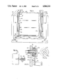
- FIG. 3 is a side-elevational view illustrating the manual drives for raising and tilting the slats
- FIG. 4 illustrates the shutter with all the slats in their closed positions
- FIG. 5 illustrates the shutter showing how the slats are raised to their open positions
- FIGS. 6, 7 and 8 illustrate a variation in the construction of the shutters and also the operation of the tilting means
- FIGS. 10a and 10b illustrate the operation of an alternative tilting means using a cord
- FIG. 11 illustrates another form of improved shutter constructed in accordance with the present invention, FIGS. 11a, 11b and 11d being sectional views along lines a--a, b--b and d--d of FIG. 11, while FIG. 11c is a sectional view along line c--c of FIG. 11b; and
- FIGS. 12-15 are fragmentary views illustrating constructional details of the shutter of FIG. 11.
- the window shutter illustrated in FIGS. 1-5 of the drawings is adapted to be applied over a window for controlling the passage of light and air through the window.
- the shutter comprises a frame, generally designated 2, adapted to be mounted in the window opening, which frame includes a plurality of horizontal slats 4 mounted, via their end-projecting shafts 5, in vertically-space relationship to and between a pair of flexible elongated mounting members 6, 8 (FIGS. 4, 5).
- the slats may be moved from a normal, closed position illustrated in FIGS. 1 and 4, to an open raised position as illustrated in FIG. 5, by rotating a handle 10; they may also be simultaneously tilted about their horizontal axis from a vertical, closed position, to a horizontal, open position, by rotating a second handle 12 coaxial with respect to handle 10.
- the flexible, elongated mounting members 6, 8, between which the slats 4 are pivotably mounted, are flexible strips or belts disposed within a pair of channel members 14, 16 fixed to the opposite sides of the shutter frame 2.
- the two channel members 14, 16 thus serve as guides or rails for positively guiding the movement of the shafts 5 of the slats 4 when the slats are moved either to their lower, closed positions or to their upper, open positions, as well as to any tilted position.
- FIGS. 2-5 best illustrate the arrangement for raising and lowering the slats by rotating handle 10.
- handle 10 drives a drum 18 to which is secured the opposite ends of a cord 20 for raising and lowering the slats 4.
- One end of cord 20 is secured to drum 18, and the opposite end is wound around five direction-changing rollers 21, 22, 23, 24 and 25, before returning back and secured to drum 18.
- This arrangement provides two vertical stretches 20a, 20b which are moved together upwardly when drum 18 is rotated in one direction, and downwardly when the drum is rotated in the opposite direction.
- Shaft 5 of the lowermost slat 4 is connected to stretches 20a, 20b of cord 20, rather than to the flexible belts 6, 8, to which the shafts 5 of the other slats are connected.
- Each slat 4, except the lowermost slat, is formed with an extension 28 depending from its lower edge for cooperation with the upper edge of the underlying slat.
- the cooperating faces in the extensions 28, and/or in the upper edge of the underlying slat 4, are preferably slanted.
- the arrangement is such that when handle 10 is rotated to raise stretches 20a, 20b of cord 20, this raises the lowermost slat 4; and as its upper edge engages extension 28 of the next overlying slat, that slat is pivoted towards the horizontal position.
- continued rotation of handle 10 causes each slat 4 to be pivoted horizontally and then raised, until all the slats have been raised to their open positions, whereupon the slats assume a stacked horizontal position above the window opening.
- Rotation of the second handle 12 effects the simultaneous tilting of all the slats about their horizontal shafts 5.
- Handle 12 may be locked against rotation so as to lock the slats 4 in any desired tilted position.
- Extension 30a of the handle shank 30 is urged into one of the recesses 38 of stop member 36 by a spring 40 in order to lock handle 12 in position against rotation, but the handle may be manually released for rotation by merely pushing handle 12 inwardly against spring 40 to unseat its extension 30a from the recesses 38 of stop member 36.
- cord 34 is wound over a pin 42 and moves a tilt bar 44 coupled to the slats 4' by means of an extension 46 pivotal to the frame and to the tilt bar.
- a tilt bar 44 coupled to the slats 4' by means of an extension 46 pivotal to the frame and to the tilt bar.
- FIGS. 6 and 7 illustrate a slight variation in the construction of each slat, therein designated 4', in that the extension 28' is at the upper part of each slat and cooperates with the lower edge of the overlying slat, rather than being at the lower part of the slat and cooperating with the upper edge of the underlying slat as in FIGS. 1-5.
- FIGS. 1 and 9 illustrate the inclusion of a key-operated lock, generally designated 50, which may be provided in order to lock the slats against forceful upward movement, e.g., by an attempted intruder.
- Lock 50 is secured to one of the channel members, e.g., channel member 16 of frame 2, just above the lowermost slat 4 when in its lowered position, and includes a bolt 52 which is projected to overlie the upper edge of the slat when the lock is operated by a key 54.
- bolt 52 when bolt 52 is in its projected position as illustrated in FIG. 9, it prevents the lowermost slat 4 from being forcefully raised, and thereby prevents an intruder from forcing the slats to their upper open positions.
- the slats 4 may be raised to their open positions by rotating handle 10 which, via cord 20 wound on drum 18, raises the two vertical cord stretches 20a, 20b to which the shaft 5 (FIG. 4) of the lowermost slat 4 is secured, thereby raising the lowermost slat.
- the extension 28 depending from the next overlying slat 4 engages the upper edge of the lowermost slat, causing the next overlying slat 4 to pivot horizontally, and then also to be raised by the continued rotation of handle 10, until all the slats have been raised to their upper positions.
- the slats may be simultaneously tilted to any desired position by first pushing handle 12 inwardly, against spring 40 (FIG. 3) in order to unseat handle extension 30a from the recesses 38 in the stop member 36, and then rotating the handle to the desired position.
- This rotation of the handle causes cord 34 to move tilt bar 44 either to its lowermost position (FIG. 6) pivoting the slats 4 to their vertical positions, or to its raised position pivoting the slats towards their horizontal positions.
- spring 40 moves the handle shank 30 axially to bring its extension 30a into one of the recesses 38 of stop plate 36, to thereby lock the handle and the slats in their tilted positions.
- FIGS. 10a and 10b illustrate an alternative arrangement whereby a cord 44' can either replace bar 4 (shown in FIGS. 6, 7, and 8), or be included in addition to bar 44.
- One end of the cord 44' is attached to each of the slat extensions 46. Its opposite end is wound around two overhead pulleys 47,48 and is directly attached to shank 30 of handle 12.
- FIG. 10a illustrates the open positions of the slats
- FIG. 10b illustrates their closed positions.
- the window shutter illustrated in FIGS. 11-15 is adapted to be mounted in the window opening of a building 102 and includes a plurality of horizontal slats 104 mounted to and between a pair of flexible elongated mounting members 106, 108.
- the slats may be moved from a normal, closed position illustrated in FIG. 11 to an open, raised position as illustrated in FIG. 13 by means of a manually-rotatable member or handle 110; they also may be simultaneously tilted about their horizontal axes from a vertical, closed position to a horizontal, open position by rotating a second manually-rotatable member or knob 112.
- the flexible, elongated mounting members 106, 108 between which the slats 104 are pivotally mounted are in the form of flexible strips or belts disposed within a pair of channel members 114, 116 fixed to the opposite sides of the shutter.
- the two channel members 114, 116 thus serve as guides for positively guiding the movement of the ends of the slats 4 when they are moved either to their lower, closed positions or to their upper, open positions.
- each of the slats 104 is pivotally mounted by means of a shaft 118 extending transversely through the respective slat and enclosed by a metal protective sleeve 120 preventing cutting-through the shaft.
- the slats and sleeves are open at their opposite ends, and each receives a pin 122 formed with an enlarged head 122a receivable within the respective channel member 114 (or 116).
- the shaft 118, sleeve 120 and pin 122 are all of square cross-section, and are received in a square cross-section opening extending through the length of the slat.
- the slats 104 are raised and lowered, upon rotation of handle 110, by means of a pair of closed-loop belts 124, 126 supported between a pair of wheels 124a, 124b and 126a, 126b and extending vertically within channel member 114, 116 on opposite sides of the slats.
- Handle 110 is coupled by a shaft 128 and bevel gearing 130 to directly drive wheel 124b of the closed-loop belt 124; and wheel 124b is coupled by a coupling rod 132 to wheel 126b for driving the closed-loop belt 126.
- Shaft 118 of the lowermost slat 104 is fixed at its opposite ends to one side of each of the two closed-loop belts 124, 126, as shown at 134, such that rotating handle 110 in one direction raises the lowermost slat 104, and rotating the handle in the opposite direction lowers the lowermost slat.
- the lowermost slat 104 When the lowermost slat 104 is raised, it picks up the overlying slats and thereby also raises them; and when the lowermost slat is lowered, it permits the overlying slats to also be lowered to their respective vertically-spaced positions between the flexible, elongated, mounting members 106, 108.
- FIGS. 11b and 11c illustrate locking mechanism for locking the handle 110 in any rotated position, and thereby locking the slats 104 in their respective raised positions.
- handle 110 is pivotally mounted to housing 102 by a pin 136 (FIG. 11b), and is urged towards the housing 102 by spring 138 interposed between the handle 110 and a cap 140.
- a locking plate 142 is secured to the housing 102 at the inner side of handle 110 by means of a plurality of fasteners 144.
- Locking plate 142 is formed with a circular array of openings or recesses 146 (FIG. 11c) adapted to selectively receive a pin 148 projecting from the inner face of handle 110.
- handle 110 In the normal condition of handle 110, spring 138 urges pin 148 into one of the openings 146 of locking plate 142, to thereby lock the handle in any rotated position. Since handle 110 is directly coupled to the two closed-loop belts 124, 126, via gearing 130 and coupling rod 132, this locks the belt and thereby the slats 104 in position. Whenever it is desired to raise or lower the slats, the operator pulls handle 110 outwardly, against the force of spring 138, to unseat pin 148 from opening 146, thereby freeing handle 110 for manual rotation in one or the other direction in order to raise or lower the slats.
- knob 112 is secured to a shank 150 passing through an opening in channel member 116.
- the portion of shank 150 within channel member 116 is formed with threads 152 cooperable with a nut 154.
- Nut 154 carries a U-shaped profile member 156 which extends vertically for the complete height of channel member 116.
- the upper and lower ends of profile member 156 are pivotally coupled to a pair of parallel-links 157a, 157b, permitting the U-shaped profile member 156 to move parallel to shank 150 of knob 112.
- each crank lever 158 includes an arm 158a received within the opening through its respective slat 104 and thereby serves as the pivot shaft therefor, and another arm 158b received within the vertically-extending U-shaped profile member 156.
- knob 112 when knob 112 is rotated in one direction, this also moves nut 154 to shift the U-shaped profile member 156, carried by nut 154, towards or away from knob 112.
- This shifting of profile members 156 pivots the slats 104 via the crank levers 158 coupling the shafts 118 of the slats to the profile member 156, such that rotating knob 112 will pivot the slats either to their vertical positions (illustrated in broken lines in FIG. 14) or to their horizontal positions (illustrated in full lines in FIG. 14), according to the direction of rotation of the knob.
- FIG. 15 illustrates a locking arrangement for securely locking the slats 104 in their lowered vertical positions to prevent an attempt of forceful entry through the slats.
- the locking device illustrated in FIG. 15 comprises a locking plate 160 slidably received within one (or both) of the channel members 116, 114.
- Locking plate 160 is formed with a plurality of notches 162 along one edge, which notches are aligned with the pins 122 of the slat shafts 118.
- Locking plate 160 is slidably supported between a pair of members 164a, 164b to either lock or release the shafts 118 with respect to notches 162, Thus, when plate 160 is moved to its full-line position illustrated in FIG.
- Locking plate 160 is provided with a knob 166 facilitating the sliding of the plate.
- the channel member (e.g., 116) receiving the locking plate 160 may be provided with a lock 168 controlled by a key 170 and adapted to project a bolt 172 outwardly in order to engage the edge of locking plate 160, and thereby to prevent its movement to the slat-releasing position.
- the slats Whenever it is desired to raise the slats 104, the slats must first be pivoted to their horizontal positions by operating knob 112, and they may then be raised by rotating handle 110.
- rotation of handle 110 rotates the two closed-loop belts 124, 126 on opposite sides of the slats; the connection 134 of the lowermost slat 104 to the two belts causes the lowermost slat to rise and, during its rising movement, to pick-up the overlying slats 104.
Abstract
Description
Claims (12)
Applications Claiming Priority (4)
| Application Number | Priority Date | Filing Date | Title |
|---|---|---|---|
| IL82951 | 1987-06-22 | ||
| IL82951A IL82951A0 (en) | 1987-06-22 | 1987-06-22 | Window shutter |
| IL86526 | 1988-05-27 | ||
| IL8652688A IL86526A (en) | 1988-05-27 | 1988-05-27 | Window shutter |
Publications (1)
| Publication Number | Publication Date |
|---|---|
| US4846244A true US4846244A (en) | 1989-07-11 |
Family
ID=26321689
Family Applications (1)
| Application Number | Title | Priority Date | Filing Date |
|---|---|---|---|
| US07/208,530 Expired - Lifetime US4846244A (en) | 1987-06-22 | 1988-06-20 | Window shutter |
Country Status (4)
| Country | Link |
|---|---|
| US (1) | US4846244A (en) |
| EP (1) | EP0296420B1 (en) |
| AU (1) | AU608189B2 (en) |
| DE (1) | DE3876309T2 (en) |
Cited By (14)
| Publication number | Priority date | Publication date | Assignee | Title |
|---|---|---|---|---|
| US5163494A (en) * | 1991-01-11 | 1992-11-17 | Macneil Daniel J | Sectional door installation |
| US5887637A (en) * | 1997-05-05 | 1999-03-30 | Phyper; Duncan | Aperture covering system |
| US5996674A (en) * | 1997-05-08 | 1999-12-07 | Gatewood; Denise D. | Rapid installation curtain |
| US6453972B1 (en) | 1998-02-17 | 2002-09-24 | Tristeck Ltd. | Roll-up shutter |
| WO2004070156A1 (en) | 2003-01-30 | 2004-08-19 | Parma Shutter Technologies Ltd. | Door shutter mechanism |
| US20040204714A1 (en) * | 1997-08-16 | 2004-10-14 | Mingyan Liu | Spinal implant and cutting tool preparation accessory for mounting the implant |
| US6901825B1 (en) | 2004-01-02 | 2005-06-07 | Vicmar Solutions, Inc. | E-Z shutter crank |
| US20080210388A1 (en) * | 2003-01-30 | 2008-09-04 | Parma Shutter Technologies Ltd | Stacking mechanism |
| US20100243180A1 (en) * | 2009-03-24 | 2010-09-30 | Charles Hoberman | Panel assemblies having controllable surface properties |
| US20110167729A1 (en) * | 2007-07-12 | 2011-07-14 | Maviflex | Modular mount for handling door with flexible screen |
| US20110214348A1 (en) * | 2008-11-07 | 2011-09-08 | Jeong-Won Park | Multipurpose window |
| US20160153229A1 (en) * | 2012-10-29 | 2016-06-02 | Hangzhou Wokasolar Technology Co., Ltd. | Sequential control roller system for variable a pitch shutter |
| US10407980B2 (en) * | 2017-04-12 | 2019-09-10 | Hall Labs Llc | Cordless window covering system with bearings |
| US11825771B2 (en) | 2019-04-02 | 2023-11-28 | Cnh Industrial America Llc | Infeed deck cleanout door for a header |
Families Citing this family (7)
| Publication number | Priority date | Publication date | Assignee | Title |
|---|---|---|---|---|
| GB8817437D0 (en) * | 1988-07-21 | 1988-08-24 | Curtaincraft Ltd | Window blind |
| IT1265822B1 (en) * | 1992-07-10 | 1996-12-11 | Quinto Giovanetti | ARMORED VENETIAN BLIND FOR WINDOWS AND VARIOUS ROOMS |
| ATE258643T1 (en) * | 1997-11-05 | 2004-02-15 | Johann Henkenjohann | SUN PROTECTION FOR WINDOWS OR DOORS |
| GB9818864D0 (en) * | 1998-09-01 | 1998-10-21 | Stephens David H | Heating and ventilation of dwellings |
| GB2344418B (en) * | 1998-09-01 | 2003-04-02 | David Huw Stephens | Heating and ventilation of dwellings |
| AUPP940899A0 (en) * | 1999-03-23 | 1999-04-15 | Time Developments Pty Ltd | Interactive building module |
| ES2425490T3 (en) * | 2009-05-07 | 2013-10-15 | Ludewig Gmbh | Reed door with cabinet element |
Citations (9)
| Publication number | Priority date | Publication date | Assignee | Title |
|---|---|---|---|---|
| US1373584A (en) * | 1919-11-01 | 1921-04-05 | Joseph M Armstrong | Shutter-frame |
| US2874771A (en) * | 1957-08-27 | 1959-02-24 | Muhr John | Self-storing interengaging louvers |
| US3304994A (en) * | 1964-05-19 | 1967-02-21 | Data Instr Division | Vertically sliding door |
| US3788678A (en) * | 1972-09-25 | 1974-01-29 | H Switzgable | Adjustable garage door lock |
| US4350199A (en) * | 1981-02-05 | 1982-09-21 | Isidro Pino | Quick closing gate |
| US4378043A (en) * | 1981-05-26 | 1983-03-29 | Sorenson Robert V | Pivoting screen panel for sectional garage door |
| US4444241A (en) * | 1980-10-06 | 1984-04-24 | Emil Schenker Ag | Blind or shutter for windows or the like |
| US4537237A (en) * | 1981-07-13 | 1985-08-27 | Robert E. Reid | Louvering overhead sectional door |
| US4662420A (en) * | 1981-10-05 | 1987-05-05 | Sanwa Shutter Corporation | Panel shutter mechanism |
Family Cites Families (7)
| Publication number | Priority date | Publication date | Assignee | Title |
|---|---|---|---|---|
| US2205156A (en) * | 1938-12-19 | 1940-06-18 | William A Rowley | Burglarproof blind |
| FR1041393A (en) * | 1950-08-28 | 1953-10-22 | Control device for louvered shutters | |
| FR1129755A (en) * | 1955-08-10 | 1957-01-25 | Roller shutter blind | |
| FR1475733A (en) * | 1966-01-12 | 1967-04-07 | Planet Usines | Improvements to shutters for windows and openings |
| US3853169A (en) * | 1973-10-29 | 1974-12-10 | J Music | Rotatable track-mounted shutter blinds |
| AU490853B1 (en) * | 1974-04-16 | 1976-10-21 | Felice Carretta Seto | Louvre arrangement |
| DE3511246A1 (en) * | 1985-03-28 | 1986-10-02 | Theophil Dipl.-Ing. 7300 Esslingen Pfeffer | Screening or protecting device for wall openings or the like, in particular a roller shutter or a blind |
-
1988
- 1988-06-10 DE DE8888109254T patent/DE3876309T2/en not_active Expired - Fee Related
- 1988-06-10 EP EP88109254A patent/EP0296420B1/en not_active Expired - Lifetime
- 1988-06-20 AU AU18150/88A patent/AU608189B2/en not_active Ceased
- 1988-06-20 US US07/208,530 patent/US4846244A/en not_active Expired - Lifetime
Patent Citations (9)
| Publication number | Priority date | Publication date | Assignee | Title |
|---|---|---|---|---|
| US1373584A (en) * | 1919-11-01 | 1921-04-05 | Joseph M Armstrong | Shutter-frame |
| US2874771A (en) * | 1957-08-27 | 1959-02-24 | Muhr John | Self-storing interengaging louvers |
| US3304994A (en) * | 1964-05-19 | 1967-02-21 | Data Instr Division | Vertically sliding door |
| US3788678A (en) * | 1972-09-25 | 1974-01-29 | H Switzgable | Adjustable garage door lock |
| US4444241A (en) * | 1980-10-06 | 1984-04-24 | Emil Schenker Ag | Blind or shutter for windows or the like |
| US4350199A (en) * | 1981-02-05 | 1982-09-21 | Isidro Pino | Quick closing gate |
| US4378043A (en) * | 1981-05-26 | 1983-03-29 | Sorenson Robert V | Pivoting screen panel for sectional garage door |
| US4537237A (en) * | 1981-07-13 | 1985-08-27 | Robert E. Reid | Louvering overhead sectional door |
| US4662420A (en) * | 1981-10-05 | 1987-05-05 | Sanwa Shutter Corporation | Panel shutter mechanism |
Cited By (24)
| Publication number | Priority date | Publication date | Assignee | Title |
|---|---|---|---|---|
| US5163494A (en) * | 1991-01-11 | 1992-11-17 | Macneil Daniel J | Sectional door installation |
| US5887637A (en) * | 1997-05-05 | 1999-03-30 | Phyper; Duncan | Aperture covering system |
| US5996674A (en) * | 1997-05-08 | 1999-12-07 | Gatewood; Denise D. | Rapid installation curtain |
| US20040204714A1 (en) * | 1997-08-16 | 2004-10-14 | Mingyan Liu | Spinal implant and cutting tool preparation accessory for mounting the implant |
| US20090164015A1 (en) * | 1997-08-16 | 2009-06-25 | Mingyan Liu | Spinal implant and cutting tool preparation accessory for mounting the implant |
| US7465305B2 (en) | 1997-08-26 | 2008-12-16 | Warsaw Orthopedic, Inc. | Spinal implant and cutting tool preparation accessory for mounting the implant |
| US6453972B1 (en) | 1998-02-17 | 2002-09-24 | Tristeck Ltd. | Roll-up shutter |
| US7681620B2 (en) | 2003-01-30 | 2010-03-23 | Parma Shutter Technologies Ltd | Stacking mechanism |
| WO2004070156A1 (en) | 2003-01-30 | 2004-08-19 | Parma Shutter Technologies Ltd. | Door shutter mechanism |
| US20060113045A1 (en) * | 2003-01-30 | 2006-06-01 | Tal Padan | Door shutter mechanism |
| US7370684B2 (en) | 2003-01-30 | 2008-05-13 | Parma Shutter Technologies, Ltd. | Door shutter mechanism |
| US20080210388A1 (en) * | 2003-01-30 | 2008-09-04 | Parma Shutter Technologies Ltd | Stacking mechanism |
| US6901825B1 (en) | 2004-01-02 | 2005-06-07 | Vicmar Solutions, Inc. | E-Z shutter crank |
| US20110167729A1 (en) * | 2007-07-12 | 2011-07-14 | Maviflex | Modular mount for handling door with flexible screen |
| US8439100B2 (en) * | 2007-07-12 | 2013-05-14 | Maviflex | Modular upright for service door with flexible curtain |
| US20110214348A1 (en) * | 2008-11-07 | 2011-09-08 | Jeong-Won Park | Multipurpose window |
| CN102209829A (en) * | 2008-11-07 | 2011-10-05 | 朴正圆 | Multipurpose window |
| US8555948B2 (en) * | 2008-11-07 | 2013-10-15 | Jeong-Won Park | Multipurpose window |
| CN102209829B (en) * | 2008-11-07 | 2014-05-28 | 朴正圆 | Multipurpose window |
| US20100243180A1 (en) * | 2009-03-24 | 2010-09-30 | Charles Hoberman | Panel assemblies having controllable surface properties |
| US8615970B2 (en) * | 2009-03-24 | 2013-12-31 | Charles Hoberman | Panel assemblies having controllable surface properties |
| US20160153229A1 (en) * | 2012-10-29 | 2016-06-02 | Hangzhou Wokasolar Technology Co., Ltd. | Sequential control roller system for variable a pitch shutter |
| US10407980B2 (en) * | 2017-04-12 | 2019-09-10 | Hall Labs Llc | Cordless window covering system with bearings |
| US11825771B2 (en) | 2019-04-02 | 2023-11-28 | Cnh Industrial America Llc | Infeed deck cleanout door for a header |
Also Published As
| Publication number | Publication date |
|---|---|
| AU1815088A (en) | 1988-12-22 |
| DE3876309D1 (en) | 1993-01-14 |
| AU608189B2 (en) | 1991-03-21 |
| EP0296420A3 (en) | 1989-06-07 |
| EP0296420B1 (en) | 1992-12-02 |
| EP0296420A2 (en) | 1988-12-28 |
| DE3876309T2 (en) | 1993-06-24 |
Similar Documents
| Publication | Publication Date | Title |
|---|---|---|
| US4846244A (en) | Window shutter | |
| CA2240206C (en) | Tilting mechanism for a venetian blind | |
| US5392836A (en) | Door assembly | |
| EP0727005B1 (en) | Locking assembly | |
| US7412800B2 (en) | Latching and anti-bow mechanism for a window | |
| US6453972B1 (en) | Roll-up shutter | |
| US6289963B1 (en) | Dual closure system for overhead doors | |
| CA2218003C (en) | Integrated power window lock | |
| US4936369A (en) | Vertical blind with louver rotation control | |
| US6644376B2 (en) | Single control tilt drive unit | |
| GB2087475A (en) | Device for Closing and Opening Blinds, Shutters, and Hinged Window Members in General | |
| EP0369068B1 (en) | Venetian blind assembly | |
| WO2009149708A1 (en) | Screening device with a locking mechanism for a tilt device | |
| EP0322355B1 (en) | Venetian blind | |
| EP3658734B1 (en) | Door system | |
| US5927365A (en) | Multi-directional window covering apparatus | |
| EP1270865B1 (en) | Sunblind | |
| JPH0137095Y2 (en) | ||
| EP4191014A2 (en) | Outside-mount window blind consisting of a frame with a control device for adjusting the position of the slats | |
| JP2843095B2 (en) | Louver type panel shutter | |
| JPS634795Y2 (en) | ||
| JPH0431991Y2 (en) | ||
| JP3242962B2 (en) | Shutter opening and closing drive | |
| JP2904910B2 (en) | Panel shutter | |
| AU2003204589B2 (en) | Roll-up shutter |
Legal Events
| Date | Code | Title | Description |
|---|---|---|---|
| AS | Assignment |
Owner name: PARMA DEVELOPMENTS LTD., GAN SHOMRON 37915 ISRAEL Free format text: ASSIGNMENT OF ASSIGNORS INTEREST.;ASSIGNOR:ROSENFELD, CHAIM;REEL/FRAME:004906/0724 Effective date: 19880529 Owner name: PARMA DEVELOPMENTS LTD.,ISRAEL Free format text: ASSIGNMENT OF ASSIGNORS INTEREST;ASSIGNOR:ROSENFELD, CHAIM;REEL/FRAME:004906/0724 Effective date: 19880529 |
|
| STCF | Information on status: patent grant |
Free format text: PATENTED CASE |
|
| FEPP | Fee payment procedure |
Free format text: PAYOR NUMBER ASSIGNED (ORIGINAL EVENT CODE: ASPN); ENTITY STATUS OF PATENT OWNER: SMALL ENTITY |
|
| FPAY | Fee payment |
Year of fee payment: 4 |
|
| FEPP | Fee payment procedure |
Free format text: PAYER NUMBER DE-ASSIGNED (ORIGINAL EVENT CODE: RMPN); ENTITY STATUS OF PATENT OWNER: SMALL ENTITY Free format text: PAYOR NUMBER ASSIGNED (ORIGINAL EVENT CODE: ASPN); ENTITY STATUS OF PATENT OWNER: SMALL ENTITY |
|
| FPAY | Fee payment |
Year of fee payment: 8 |
|
| SULP | Surcharge for late payment | ||
| FPAY | Fee payment |
Year of fee payment: 12 |