US4853117A - Purified water supply system - Google Patents
Purified water supply system Download PDFInfo
- Publication number
- US4853117A US4853117A US07/108,770 US10877087A US4853117A US 4853117 A US4853117 A US 4853117A US 10877087 A US10877087 A US 10877087A US 4853117 A US4853117 A US 4853117A
- Authority
- US
- United States
- Prior art keywords
- valve
- purified water
- drain
- reject
- reject water
- Prior art date
- Legal status (The legal status is an assumption and is not a legal conclusion. Google has not performed a legal analysis and makes no representation as to the accuracy of the status listed.)
- Expired - Lifetime
Links
Images


Classifications
-
- B—PERFORMING OPERATIONS; TRANSPORTING
- B01—PHYSICAL OR CHEMICAL PROCESSES OR APPARATUS IN GENERAL
- B01D—SEPARATION
- B01D61/00—Processes of separation using semi-permeable membranes, e.g. dialysis, osmosis or ultrafiltration; Apparatus, accessories or auxiliary operations specially adapted therefor
- B01D61/02—Reverse osmosis; Hyperfiltration ; Nanofiltration
- B01D61/10—Accessories; Auxiliary operations
Definitions
- This invention relates generally to improvements in purified water supply systems of the type having a reverse osmosis unit for producing purified water from an incoming supply of ordinary tap water or the like. More particularly, this invention relates to an improved purified water supply system having control means for providing effective delivery of purified water for use, while limiting fluid pressures within the system in a manner permitting relatively lightweight and economical system components.
- Water purification systems in general are relatively well-known in the art for use in producing a supply of purified water from ordinary tap water or the like.
- Such water purification systems commonly include a reverse osmosis unit connected to an incoming tap water supply, wherein the reverse osmosis unit produces two separate water outflows including a purified water supply, and a waste or reject water supply, sometimes referred to as brine, with impurities concentrated therein.
- the production of purified water is normally relatively slow whereby the purified water outflow is typically coupled to and stored within an appropriate storage vessel ready for dispensing when desired through a manually operated faucet valve or the like.
- the storage vessel for the purified water commonly includes a purified water chamber and a reject water chamber separated from each other by a movable barrier, such as a resilient diaphragm or bladder or the like.
- a movable barrier such as a resilient diaphragm or bladder or the like.
- the faucet valve While the faucet valve is closed, the purified water expands and fills the purified water chamber to expel reject water from the reject water chamber for flow to a suitable drain.
- the faucet valve is opened to create an open discharge path communicating the purified water chamber to an open discharge spout or the like.
- other valve components in the supply system function to supply a substantial flow of reject water into the reject water chamber thereby providing a fluid driving medium capable of forcing the purified water through the open discharge path to the discharge spout.
- this substantial reject water flow into the reject water chamber for purified water delivery purposes has resulted in at least temporary pressurization of the reject water chamber to a level substantially equalling tap water line pressure.
- the storage vessel In domestic or residential water supply systems wherein the tap water line pressure is typically within the range of about 40 to 150 psi, the storage vessel is thus subjected to a substantial fluid pressure during normal operation of the water supply system.
- Such pressurization of the storage vessel has required relatively rugged vessel constructions of metal or reinforced plastic or fiberglass materials, whereby the storage vessel has constituted a major cost component in the water supply system.
- the presence of relatively high fluid pressures within the storage vessel enhances the risk of occasional failure of system components such as valves, seals, etc., resulting in water leaks and accompanying risk of water damage.
- water supply systems of this general type have proposed the use of complicated valve arrangements with multiple, independently operated valve components required to control the various system water flows and pressures.
- minor irregularities in the operation of a single valve component such as leakage due to entrapped grit at a valve seat or other sealing surface, can result in system failure.
- system failures have required time consuming and costly disassembly of complicated valve components for repair purposes.
- an improved purified water supply system for use in producing and storing a supply of relatively purified water from an incoming supply of ordinary tap water or the like.
- the improved water supply system includes a compact storage vessel for containing the produced purified water available for immediate use, wherein the system includes means for limiting pressures within the storage vessel to a pressure level substantially below tap water line pressure.
- the water supply system includes a reverse osmosis unit having an inlet coupled to a supply of ordinary tap water or the like.
- the reverse osmosis unit operates in a known manner to produce dual water outflows, namely, the purified water supply with impurities substantially removed, and a supply of reject water or brine with impurities concentrated therein.
- the purified water supply is stored within the storage vessel ready for dispensing, for example, through a discharge path which can be opened upon operation of one or more faucet valves, whereas the reject water supply is ultimately discharged to an appropriate drain.
- the storage vessel comprises a relatively lightweight and preferably compact tank container defining an internal purified water chamber and a reject water chamber separated from each other by a movable barrier.
- the produced purified water supply is coupled for flow into the purified water chamber, whereas the produced reject water supply is coupled to an improved control valve assembly disposed along the purified water discharge path.
- the control valve assembly responds to the operational state of the faucet valve or valves to direct the reject water supply to the reject water chamber or, in the alternative, to the drain.
- the control valve assembly incorporates fluid pressure regulator means for limiting the fluid pressure within the reject water chamber to a pressure level substantially below tap water line pressure, thereby correspondingly regulating the fluid pressure within the entire storage vessel.
- control valve assembly responds to opening of the faucet valve or valves to supply reject water at a substantial flow rate to the reject water chamber in the storage vessel.
- This substantial reject water flow rate is effective to pressurize the reject water chamber to a sufficient fluid pressure level to provide the driving medium expelling purified water from the storage vessel for flow along the discharge path.
- the control valve assembly maintains the pressure within the reject water chamber at a pressure level substantially below tap water line pressure to avoid subjecting the pressure vessel to relatively high fluid pressures.
- the selected maximum reject water chamber pressure level is maintained when the faucet valve or valves are closed.
- the control valve assembly operates to substantially relieve the fluid pressure within the storage vessel when purified water dispensing is halted.
- control valve assembly includes a piston member associated with the purified water discharge path and adapted for movably responding upon fluid pressure changes along that path attributable to opening of the faucet valve or valves.
- This movement of the piston member displaces a slotted valve head of a reject water flow control valve from a flow limiting position to a fully open position permitting relatively high flow of reject water into the reject water chamber of the storage vessel.
- the piston member movement directly or indirectly results in displacement of a reject water drain valve to a closed position thereby insuring sufficient pressure rise in the reject water chamber to expel purified water through the open discharge path.
- the drain valve opens sufficiently to maintain chamber pressure within the storage vessel at a selected threshold pressure below tap water line pressure. In other embodiments, the drain valve is opened fully to relieve storage vessel pressure substantially to an atmospheric pressure level.
- the control valve assembly has a simplified construction adapted for reliable, substantially failsafe operation of the various valve components therein. More particularly, the pressure responsive piston member, the slotted valve head controlling reject water flow into the storage vessel, and the reject water drain valve are arranged in an inline configuration for substantially coaxial linear motion. Movement of the piston member is transmitted directly to the slotted valve head and further is transmitted directly to the drain valve to provide positive mechanical actuation.
- FIG. 1 is a diagrammatic view illustrating an improved purified water supply system embodying the novel features of the invention
- FIG. 2 is an enlarged fragmented vertical sectional view illustrating construction details of one preferred faucet valve assembly
- FIG. 3 is an enlarged fragmented vertical sectional view depicting construction details of a lower portion of the faucet valve assembly of FIG. 2;
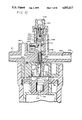
- FIG. 4 is an enlarged fragmented vertical sectional view depicting a preferred control valve assembly for use with the invention
- FIG. 5 is a further enlarged fragmented sectional view depicting the control valve assembly in an open position during purified water dispensing
- FIG. 6 is an enlarged fragmented vertical sectional view similar to FIG. 5 but depicting control valve assembly movement upon termination of purified water dispensing;
- FIG. 7 is an enlarged fragmented vertical sectional view similar to FIG. 4 and depicting one alternative embodiment of the control valve assembly for use with the invention
- FIG. 8 is a further enlarged fragmented vertical sectional view of the control valve assembly of FIG. 7, and depicting the control valve assembly in an open position during purified water dispensing;
- FIG. 9 is an enlarged fragmented vertical sectional view similar to FIG. 8 and depicting control valve assembly movement upon termination of purified water dispensing;
- FIG. 10 is another fragmented vertical sectional view similar to FIG. 4 but depicting another alternative form of the invention.
- FIG. 11 is a further enlarged fragmented vertical sectional view similar to FIG. 10 and depicting the control valve assembly in an open condition;
- FIG. 12 is an enlarged fragmented vertical sectional view similar to FIG. 11 but depicting control valve assembly movement when purified water dispensing is terminated.
- FIG. 13 is still another fragmented vertical sectional view similar to FIG. 4 but depicting a somewhat simplified alternative embodiment of the invention
- FIG. 14 is an enlarged fragmented vertical sectional view similar to a portion of FIG. 13 and depicting the control valve assembly in an open position during purified water dispensing;
- FIG. 15 is an enlarged fragmented vertical sectional view similar to FIG. 14 and showing reclosure of the control valve assembly at the conclusion of purified water dispensing.
- an improved purified water supply system is referred to generally by the reference numeral 10 in FIG. 1.
- the water supply system 10 includes a reverse osmosis unit 12 for converting an ordinary tap water supply or the like into a relatively pure supply of water which is stored temporarily within a relatively lightweight and compact storage vessel 14.
- the purified water within the storage vessel 14 is delivered on demand for use by operation of a faucet valve assembly 16.
- a control valve assembly 18 functions in cooperation with the faucet valve assembly 16 to insure reliable delivery of the purified water from the storage vessel 14, while limiting the fluid pressure within the storage vessel to a pressure level substantially less than tap water line pressure.
- the improved purified water supply system 10 of the present invention is designed particularly for use in residential and other domestic applications to produce a ready supply of relatively pure water from ordinary tap water or the like.
- the system 10 utilizes the reverse osmosis unit 12 to convert an incoming supply of ordinary tap water into dual water outflows including a supply of relatively pure water and a waste or reject water supply, sometimes referred to as brine, having impurities concentrated therein.
- the purified water supply is normally coupled to and stored within the storage vessel 14 ready for use on demand for drinking, cooking, etc.
- the purified water supply can be coupled to multiple use sites such as an icemaker or a chilled water station of the type included in many modern refrigerator units.
- the control valve assembly 18 operates in conjunction with opening and closing of an appropriate faucet valve at each one of the multiple use sites to insure reliable purified water delivery.
- the water supply system 10 advantageously utilizes the generated supply of reject water as a driving medium for expelling purified water from the storage vessel 14, when dispensing of purified water is desired.
- the control valve assembly 18 regulates the supply of reject water to the storage vessel in a manner limiting maximum storage vessel internal pressure to a threshold level substantially less than tap water line pressure.
- the reject water supply is used to provide a sufficient driving force to the stored purified water for dispensing purposes, while maintaining internal vessel pressures relatively low, thereby avoiding internal pressures at tap water line pressures which can range between 40-150 psi.
- the use of relatively low vessel pressures beneficially permits economic storage vessel construction of lightweight molded plastic or the like, to correspondingly reduce the overall cost and complexity of the water supply system.
- a tap water supply line 19 of a standard residential water supply system or the like is coupled to an inlet throttle valve 20.
- This throttle valve 20 is normally open to permit tap water flow through a feed conduit 22 to an inlet 24 on the reverse osmosis unit 12.
- the reverse osmosis unit 12 includes an internal membrane (not shown) which functions in a manner known to those skilled in the art to separate the incoming water tap water into the purified water supply and the reject water supply.
- the purified water supply is discharged from the reverse osmosis unit 12 through an outlet conduit 26, whereas the reject water is discharged through a separate outlet conduit 28.
- the purified water supply produced by the reverse osmosis unit 12 is coupled by the conduit 26 for flow alternately to a filter unit 30 containing carbon filter material or the like, or through a conduit 32 into a purified water chamber 34 within the storage vessel 14.
- this storage vessel 14 comprises a relatively lightweight tank container formed from a pair of cup-shaped sections 35 and 36 mounted one on top of the other in facing relation and securely connected by a circumferential band 38 or the like fastened about outwardly radiating, mating flanges 39 and 40.
- a movable barrier 41 such as a cup-shaped resilient diaphragm or the like has its periphery trapped between the flanges 39 and 40 and functions to divide the internal volume of the vessel 14 into the purified water chamber 34 and an upper reject water chamber 42.
- the reject water supply produced by the reverse osmosis unit 12 flows through the reject water conduit 28 to an associated inlet port 44 of the control valve assembly 18.
- the control valve assembly 18 redirects the reject water supply through an appropriate conduit 46 for flow into the reject water chamber 42 of the storage vessel 14, or, in the alternative, through a drain conduit 50 to the faucet valve assembly 16 ultimately for discharge to an appropriate drain through a drain tube 52.
- control valve assembly 18 is connected inline with a discharge path through which purified water may be discharged for the storage vessel 14, wherein this discharge path may lead to multiple sites of use of the purified water such as the faucet valve assembly 16 via a primary discharge conduit 54, or for alternate flow through a secondary discharge conduit 58 to an alternative use site 60, for example, such as an icemaker or a chilled water drinking station in a modern refrigerator.
- the reverse osmosis unit 12 produces purified water which expands and fills the purified water chamber 34 in the storage vessel 14.
- reject water produced by the reverse osmosis unit is coupled to the faucet valve assembly 16 for flow through the drain tube 52 to drain.
- reject water within the vessel reject water chamber 42 is expelled by the expanding purified water chamber for flow through the control valve assembly 18 and further to drain.
- the movable barrier 41 advantageously contacts a pressure plate 61 forming a portion of the inlet throttle valve 20 to move a throttle valve member 62 to a closed position throttling or halting incoming tap water flow to the system.
- the faucet valve assembly 16 is normally mounted on the drain board 17 or the like of a sink and includes a movable valve handle 64 biased by a spring 65 (FIG. 2) toward a position permitting a valve member 66 (FIG. 3) to be carried by a spring 77 to a normally closed position.
- a movable valve handle 64 biased by a spring 65 (FIG. 2) toward a position permitting a valve member 66 (FIG. 3) to be carried by a spring 77 to a normally closed position.
- the faucet handle 64 when the faucet handle 64 is depressed to the dotted line position shown in FIG. 1, the handle 64 bears against and depresses a tubular valve stem 68 having a stop 69 thereon for displacing the valve member 66 to an open position, as viewed in dotted lines in FIG. 3.
- valve member 66 permits flow of purified water from the vessel 14 through the associated conduit 54, and upwardly though a now-open discharge passage 70 for discharge through a discharge spout 72 (FIG. 1).
- a substantial reject water flow is directed into the vessel reject water chamber 42 at a sufficient pressure to provide a fluid driving medium for forcing the purified water to flow in a reliable, accurate matter through the now-open discharge path.
- the purified water discharge path may direct the purified water to one or more additional points of use upon appropriate opening of a faucet valve (not shown) or the like at that remote use site.
- the system Upon termination of purified water dispensing at the faucet valve assembly 16 and/or at other use sites, the system reverts to a normal mode as described previously wherein the purified water chamber 34 is refilled with produced purified water.
- reject water produced by the reverse osmosis unit 12 as well as water within the reject water chamber 42 are coupled via the drain conduit 50 to drain via the faucet valve assembly 16.
- this reject water flow passes upwardly through the tubular valve stem 68 for discharge into a vented receiver 73 thereby providing an air gap for the drain portion of the system. From the receiver 73, the reject water spills into a drain path 74 for passage to and flow through the drain tube 52.
- the structure and operation of the exemplary faucet valve assembly 16 has been described briefly herein, it being understood that various faucet valve assembly arrangements may be used in the system of the present invention.
- the illustrative faucet valve assembly (FIGS. 1-3) provides a preferred construction corresponding generally with that shown and described in the inventor's U.S. Pat. No. 4,585,554, and related continuation application Ser. No. 125,777, filed Nov. 25, 1987, which are incorporated by reference herein.
- multiple faucet type valves may be used for purified water dispensing at multiple sites of use, although only one reject water drain arrangement is required.
- the control valve assembly 18 comprises an assembled multi-part valve housing 75 adapted for mounting in any suitable manner onto the top or discharge side of the filter unit 30.
- This valve housing 75 defines a lower inlet port 76 in flow communication with the purified water chamber 34 in the storage vessel 14 via the filter unit 30 and the purified water conduit 32. From the inlet port 76, the purified water is free to flow initially into a pressure chamber 78 and then to a pair of pure water outlets 80 and 81 leading respectively to the faucet valve unit 16 and to the remote use site 60. Purified water flow through these outlets to the use sites is turned on and off, of course, by the operational state of faucet valve members at those use sites. Additional pure water outlets may be provided, as desired.
- a pressure responsive piston member 82 defines a movable wall lining one side of the pressure chamber 78 within the control valve housing 75. As shown in FIG. 4, the outboard face of this pressure responsive piston member 82 is lined by a fabric reinforced resilient diaphragm 84 mounted on the housing to accommodate piston member displacement with respect to the pressure chamber 78. The inboard face of the piston member 82 is exposed to an internal chamber 85 vented to atmosphere through a vent 86. A biasing spring 88 reacts between the housing 75 and the inboard side of the piston member 82 for urging the piston normally in a direction reducing the volume of the pressure chamber 78.
- the movable piston member 82 carries an elongated stem 90 which projects through the housing 75 in a direction away from the pressure chamber 78.
- the stem 90 extends upwardly through a seal diaphragm 89 into a reject water flow path 92 communicating between the reject water inlet 44 and an outlet 93 leading to the storage vessel 14, and further through a valve seat 94 disposed along the flow path 92 before terminating in an upper stem portion 90' of somewhat enlarged diameter.
- a valve head 96 of a reject water flow control valve is slidably carried on the valve stem 90 below the upper stem portion 90' and is normally biased by a spring 97 reacting between the underside of the valve head 96 and lower shoulder 98 of the stem 90 to urge the valve head 96 toward the seat 94.
- the valve head 96 has a slot 99 in the face thereof to permit a restricted or limited reject water flow through the flow path 92 when the valve head 96 is on the seat 94.
- the valve head 96 is maintained in this flow limiting position by the combined action of the biasing spring 97 and the piston member 82 when the fluid pressure in the pressure chamber 78 is relatively high, namely, when all faucet valves for dispensing purified water are closed.
- the pressure in the chamber 78 is reduced whereby the piston member 82 descends to decrease the chamber volume. This displacement of the piston member 82 draws downwardly on the stem 90 to slide a shoulder 100 on the lowermost end of the enlarged stem portion 90' into contact with the valve head 96.
- an upper drain valve 101 within the control valve assembly 18 is positively seated in a closed position to halt passage of reject water to the drain. More specifically, as viewed in FIGS. 4 and 5, opening movement of the lower valve head 96 is accompanied by downward motion of the upper stem portion 90' to spaced relation with a support piston 102 connected to the drain valve 101. When this occurs, a valve spring 104 displaces the support piston in a downward direction to carry the drain valve 101 into seated relation with an associated valve seat 106 closing a drain path 108 leading from the reject water flow path 92 to the drain conduit 50 and ultimately to the drain.
- the substantial flow of reject water is guided in its entirety into the reject water chamber 42 of the storage vessel, resulting in expansion of the reject water chamber at a sufficient pressure to contract the size of the purified water chamber 34 and force the purified water from the vessel through the now-open discharge path.
- the closed drain valve 101 insures the presence of sufficient fluid pressure with the reject water chamber to provide the necessary fluid driving medium.
- the open condition of one or more faucet valves for purified water dispensing prevents any significant pressure rise in the vessel 14 during this mode of operation.
- the continued albeit slow reject water flow into the reject water chamber 42 causes the vessel pressure to continue to rise. This results in a corresponding slow continued pressure rise within the pressure chamber 78, thereby displacing the piston member 82 and its stem 90 further with respect to the now-seated valve head 96.
- the upper portion 90' of the stem protrudes upwardly through a seal unit 110 and eventually moves into contact with the underside of the drain valve support piston 102. When this occurs, further pressure increase in the pressure chamber 78 causes further displacement of the stem portion 90' sufficiently to open the drain valve 101 relative to its seat 106.
- the drain valve 101 is opened by an increment sufficient to achieve partial pressure relief within the reject water chamber 42 by bleeding a small amount of the reject water therein.
- the drainage bleed of reject water occurs when the vessel pressure reaches a predetermined threshold selected to be substantially below tap water line pressure and continues in sufficient quantity to maintain vessel pressure at the set threshold pressure to drain reject water from the vessel 14 as the purified water chamber 34 refills.
- the specific threshold pressure can be selected by appropriate design of the surface area of the piston member 82 and the forces applied by the various springs in the system.
- FIGS. 4-6 maintains the vessel pressure level substantially at the preset threshold refilling of the purified water chamber 34 when all of the faucet valves in the system are closed.
- This selected preset threshold will normally be chosen at about 17-25 psi--a pressure level significantly below tap water line pressure to avoid applying relatively high fluid pressures to the storage vessel 14--and further selected to avoid undue backpressure applied to the reverse osmosis unit during normal production of purified water.
- This relatively low threshold pressure can be offset economically by moderate increases in membrane surface area provided in the reverse osmosis unit.
- the threshold pressure in the reject water chamber can be set lower, with corresponding decreases in purified water delivery rate during dispensing procedures.
- FIGS. 7-9 depict one alternative construction for the reject water drain valve used in the purified water system, with the remaining system components being otherwise identical to those shown and described in FIGS. 1-6.
- a drain valve 120 is biased by a spring 122 toward a normal fully opened position relative to an associated valve seat 124. This drain valve 120 is maintained in the open position during normal refilling of the vessel 14 with purified water to correspondingly minimize backpressure applied to the reverse osmosis unit 12. However, during dispensing of purified water upon opening of one or more faucet valves in the system, the drain valve 120 is moved to a fully closed position to insure generation of sufficient pressure in the vessel 14 for proper purified water delivery purposes.
- the drain valve 120 is carried by a lower support piston 126, in the same manner previously described with respect to FIGS. 4-6.
- the support piston 126 and the drain valve 120 are biased toward an open position by the spring 122 within a chamber 123 and reacting between the seal unit 110 and the underside of the support piston 126. Accordingly, when the system faucet valves are closed such that purified water is not being dispensed, the drain valve 120 is fully opened to permit substantial drainage flow of reject water through the drain path 108, thereby maintaining the vessel pressure at a substantially minimum pressure approaching atmospheric pressure.
- This positively closed position is achieved, in this embodiment, by sliding motion of an O-ring 120' on the drain valve which slides into and effectively locks within a shallow groove 124' in the valve seat structure.
- the O-ring may be mounted in the valve seat structure and the groove formed in the drain valve 120. In either case, in this configuration, the control valve assembly permits a substantial reject water flow through the path 92 into the reject water chamber 42, while the drain valve 120 is closed, to insure fluid-activated delivery of the purified water from the storage vessel.
- a check valve 136 (FIG. 7) is provided at the inlet port 76 to the control valve assembly to prevent loss of pressure in the pressure chamber 78 until subsequent flow of purified water for dispensing purposes is desired.
- FIGS. 10-12 Another alternative embodiment of the control valve assembly is shown in FIGS. 10-12, wherein the control valve assembly includes a modified drain valve arrangement for fully opening a reject water drain valve 140 during normal refilling of the storage vessel with purified water.
- the control valve assembly again includes a pressure chamber 78 within which a significant fluid pressure is maintained separate from the water storage vessel by means of a check valve 136 or the like.
- the normal fluid pressure within this pressure chamber 78 positions the piston member 82 and its stem 90 for normal spring loaded seating of the slotted valve head 96 disposed along the reject water flow path 92, all in the manner described previously with respect to FIGS. 1-9.
- reject water is permitted to flow through the valve head slot 99 at a limited flow rate for further passage through the drain path 108 and past the drain valve 140 to drain.
- a region of the stem 90 is hollow to include an upper vent port 142 disposed within a small control chamber 144 between the seal unit 110 and a support piston 146 for the drain valve 140.
- the hollow stem also includes a second or lower vent port 148 positioned normally above the valve head 96 at the upstream side thereof (FIG. 10). Downward motion of the valve stem 90 to open the valve head transitions the lower port 148 to a position below the valve head 96 (FIG. 11) thereby exhausting the pressure within the control chamber 144.
- a spring 150 reacting between a portion of the housing and the drain valve support piston 146 functions to displace the drain valve 140 to a positively closed position.
- the drain valve 140 thus insures that the substantial flow of reject water through the open path 92 is guided into the storage vessel to provide the fluid driving medium for dispensing the purified water.
- the pressure chamber 78 is repressurized in the same manner described previously.
- the stem 90 returns in the upward direction to permit reseating of the slotted valve head 96. Further upward travel of the stem 90 retransitions the lower port 148 to a position at the upstream side of the valve head 96 and therefore repressurizes the control chamber 144 associated with the upper vent port 142.
- Such repressurization of the chamber 142 overcomes the drain valve spring 150 to positively re-open the drain valve 140, thereby relieving vessel pressure.
- FIGS. 13-15 A further alternative preferred form of the invention is shown in FIGS. 13-15 wherein a simplified drain valve 160 is formed integrally on the upper stem portion 90' of the elongated valve stem 90.
- the geometry of the drain valve 160 is designed for rapid closure when the valve head 96 is opened during purified water dispensing.
- the drain valve 160 is formed to insure substantially full closure of the valve head 96 when purified water dispensing is halted, prior to reopening of the drain valve.
- FIGS. 13-15 depict the reject water flow regulating valve head 96 mounted on the valve stem 90 for sliding movement under the influence of a biasing spring 97 into normal, substantially closed seated relation upon the valve seat 94.
- a biasing spring 97 In this normally closed position, when purified water dispensing is halted and the purified water chamber in the storage vessel 14 (FIG. 1) is being refilled, the valve stem 90 extends above the valve head 96 and merges with a diametrically enlarged upper stem portion 90'.
- this upper stem portion 90' extends through a seal unit 110 into an upper region of the control valve assembly to terminate in the integrally formed drain valve 160 positioned in operative relation with a valve seat 124 unit including an O-ring seal 120' or the like.
- one or more of the purified water faucet valves is opened to result in a pressure drop within the lower pressure chamber 78 of the control valve assembly.
- the piston member 82 descends into the pressure chamber 78 to draw the stem 90 in a downward direction with a sliding action through the still-closed valve head 96.
- Sufficient downward displacement of the stem 90 moves the shoulder 100 thereon into bearing engagement with the valve head 96 to displace the valve head from the closed position (FIG. 13) to an open position (FIG. 14).
- such downward movement of the valve stem 90 displaces a groove 160' in the drain valve 160 from an open position generally aligned with the valve seat O-ring 120' (FIG.
- Opening of the valve head 96 permits a substantial reject water flow into the reject water chamber of the storage vessel 14 (FIG. 1) to correspondingly displace purified water from the storage vessel through the open faucet valve or valves.
- the drain valve 160 remains closed throughout this dispensing cycle to insure positive and reliable purified water dispensing yet the fluid pressure within the storage vessel 14 remains substantially below tap water line pressure due to the open nature of the faucet valve.
- this drain valve reopening occurs at a storage vessel pressure threshold substantially below tap water line pressure, due to the design characteristics of the spring-loaded piston member, to prevent exposure of the storage vessel to high fluid pressures.
- a check valve 136 may be again provided at the inlet port 76 of the pressure chamber 78 to prevent chamber pressure loss until subsequent purified water dispensing is initiated.
- check valve 136 is not required in this embodiment since the piston member 82 responding to pressure within the chamber 78 will open the drain valve 160 by a small increment sufficient to achieve partial pressure relief within the reject chamber, in the same manner as described with respect to FIGS. 1-6.
- valve head 96 of the reject water flow control valve and the reject water drain valve are arranged for simple and reliable operation. All of the valve components are aligned generally coaxially for actuation in a linear manner upon movement of the pressure responsive piston member. Importantly, the valve head 96 is fully reseated in each embodiment prior to drain valve reopening.
- the improved purified water supply system of the present invention provides means for regulating the pressure of a purified water storage vessel to maximum pressure level substantially below tap water line pressure.
- the storage vessel is not subjected to high pressure levels and can thus be constructed from lightweight materials.
Landscapes
- Chemical & Material Sciences (AREA)
- Engineering & Computer Science (AREA)
- Water Supply & Treatment (AREA)
- Nanotechnology (AREA)
- Chemical Kinetics & Catalysis (AREA)
- Separation Using Semi-Permeable Membranes (AREA)
Abstract
Description
Claims (27)
Priority Applications (7)
| Application Number | Priority Date | Filing Date | Title |
|---|---|---|---|
| US07/108,770 US4853117A (en) | 1987-10-15 | 1987-10-15 | Purified water supply system |
| AT88910296T ATE98514T1 (en) | 1987-10-15 | 1988-10-12 | SUPPLY SYSTEM FOR PURIFIED WATER. |
| DE88910296T DE3886381D1 (en) | 1987-10-15 | 1988-10-12 | DELIVERY SYSTEM FOR PURIFIED WATER. |
| AU27833/89A AU2783389A (en) | 1987-10-15 | 1988-10-12 | Purified water supply system |
| PCT/US1988/003551 WO1989003238A1 (en) | 1987-10-15 | 1988-10-12 | Purified water supply system |
| EP88910296A EP0336961B1 (en) | 1987-10-15 | 1988-10-12 | Purified water supply system |
| CA000579977A CA1321548C (en) | 1987-10-15 | 1988-10-13 | Purified water supply system |
Applications Claiming Priority (1)
| Application Number | Priority Date | Filing Date | Title |
|---|---|---|---|
| US07/108,770 US4853117A (en) | 1987-10-15 | 1987-10-15 | Purified water supply system |
Publications (1)
| Publication Number | Publication Date |
|---|---|
| US4853117A true US4853117A (en) | 1989-08-01 |
Family
ID=22323947
Family Applications (1)
| Application Number | Title | Priority Date | Filing Date |
|---|---|---|---|
| US07/108,770 Expired - Lifetime US4853117A (en) | 1987-10-15 | 1987-10-15 | Purified water supply system |
Country Status (6)
| Country | Link |
|---|---|
| US (1) | US4853117A (en) |
| EP (1) | EP0336961B1 (en) |
| AU (1) | AU2783389A (en) |
| CA (1) | CA1321548C (en) |
| DE (1) | DE3886381D1 (en) |
| WO (1) | WO1989003238A1 (en) |
Cited By (30)
| Publication number | Priority date | Publication date | Assignee | Title |
|---|---|---|---|---|
| US5082557A (en) * | 1990-04-02 | 1992-01-21 | Rainsoft Water Conditioning Co. | Control head for water purifier |
| US5160608A (en) * | 1990-10-11 | 1992-11-03 | Culligan International Company | High efficiency water treatment system |
| US5290442A (en) * | 1991-09-24 | 1994-03-01 | Clack Corporation | Self-contained, purified drinking water refrigerator storage apparatus |
| US5332599A (en) | 1993-07-19 | 1994-07-26 | The Gillette Company | Aqueous correction fluid |
| US5662793A (en) * | 1996-01-05 | 1997-09-02 | Beall, Jr.; Richard W. | Valve assembly of a reverse osmosis water purification system |
| US5813245A (en) * | 1996-10-25 | 1998-09-29 | White Consolidated Industries, Inc. | Pressure relief circuit for refrigerator contained water filter |
| US5865209A (en) * | 1996-06-18 | 1999-02-02 | Qmp, Inc. | Air gap adapter |
| US20040094202A1 (en) * | 2002-08-09 | 2004-05-20 | Kawolics Raymond P. | Modular air gap device and faucet including same |
| US20070045165A1 (en) * | 2005-08-26 | 2007-03-01 | Next-Ro, Inc. | Reverse osmosis filtration systems |
| US20070045327A1 (en) * | 2005-08-26 | 2007-03-01 | Next-Ro, Inc. | Reverse osmosis filtration system storage tanks |
| US20070215531A1 (en) * | 2006-03-17 | 2007-09-20 | Andreas Wawrla | Water-treatment appliance |
| WO2007125526A2 (en) * | 2006-04-30 | 2007-11-08 | Noga Engineering Ltd. | Reverse osmosis water purification system |
| US20070256977A1 (en) * | 2006-05-02 | 2007-11-08 | Watts Water Technologies, Inc. | Reverse osmosis water filtering system |
| US20100116742A1 (en) * | 2008-11-07 | 2010-05-13 | The Good Water Company , Inc. | Reverse osmosis system |
| US20100116724A1 (en) * | 2008-10-09 | 2010-05-13 | Watts Water Technologies, Inc. | Reverse osmosis water filtering system |
| US20100116741A1 (en) * | 2008-11-07 | 2010-05-13 | The Good Water Company, Inc. | Reverse Osmosis System |
| US7740766B2 (en) | 2001-08-23 | 2010-06-22 | The Procter & Gamble Company | Methods for treating water |
| US7740765B2 (en) | 2001-08-23 | 2010-06-22 | The Procter & Gamble Company | Methods for treating water |
| US7749394B2 (en) | 2001-08-23 | 2010-07-06 | The Procter & Gamble Company | Methods of treating water |
| US20100243942A1 (en) * | 2009-03-30 | 2010-09-30 | Burrows Bruce D | Control valve for a reverse osmosis water purification system |
| US7850859B2 (en) | 2001-08-23 | 2010-12-14 | The Procter & Gamble Company | Water treating methods |
| US7922008B2 (en) | 2001-08-23 | 2011-04-12 | The Procter & Gamble Company | Water filter materials and water filters containing a mixture of microporous and mesoporous carbon particles |
| US20110120928A1 (en) * | 2009-11-25 | 2011-05-26 | Watts Water Technologies, Inc. | Easy change filter assembly for reverse osmosis membrane water purification system |
| US8409386B1 (en) | 2010-02-22 | 2013-04-02 | Next-Ro, Inc. | Storage tank assemblies and methods for water on water reverse osmosis systems |
| US9731984B2 (en) | 2010-02-19 | 2017-08-15 | Topper Manufacturing Corporation | Reverse osmosis systems with built in pressure regulation |
| US9919933B2 (en) | 2013-12-18 | 2018-03-20 | Ds Services Of America, Inc. | Water purification system with active vibration |
| US10022755B2 (en) * | 2011-07-28 | 2018-07-17 | Airbus Operations Gmbh | System for pipe treatment |
| US10196292B2 (en) | 2006-10-12 | 2019-02-05 | Ds Services Of America, Inc. | Drainless reverse osmosis water purification system |
| CN109368723A (en) * | 2018-12-19 | 2019-02-22 | 珠海格力电器股份有限公司 | Purifying drinking appliance and its discharge of wastewater mechanism |
| US10780377B2 (en) | 2016-11-30 | 2020-09-22 | Watts Regulator Co. | Sanitizing filter system and method for a residential water filtering system |
Families Citing this family (3)
| Publication number | Priority date | Publication date | Assignee | Title |
|---|---|---|---|---|
| CN103691321B (en) * | 2014-01-13 | 2016-08-17 | 江苏正本净化节水科技实业有限公司 | Water-saving RO machine |
| CN105481131A (en) * | 2016-01-29 | 2016-04-13 | 江苏沁尔康环境电器有限公司 | Repurifying type membrane water purifier |
| CN110228827A (en) * | 2019-07-17 | 2019-09-13 | 莱克电气绿能科技(苏州)有限公司 | A kind of former, waste water isolation water tank and water purifier |
Citations (27)
| Publication number | Priority date | Publication date | Assignee | Title |
|---|---|---|---|---|
| US2954799A (en) * | 1955-05-24 | 1960-10-04 | Union Tank Car Co | Control for water softeners |
| US3089513A (en) * | 1960-12-01 | 1963-05-14 | Jr Chester Howard Kirk | Combination fill valve and expansion tank |
| US3493496A (en) * | 1968-05-13 | 1970-02-03 | Desalination Systems | Purified water supply apparatus and method |
| US3542199A (en) * | 1969-07-24 | 1970-11-24 | Donald T Bray | Reverse osmosis water purification unit |
| US3568843A (en) * | 1968-12-06 | 1971-03-09 | Desalination Systems | Water storage system for reverse osmosis purification unit |
| US3719593A (en) * | 1970-09-25 | 1973-03-06 | J Astil | Water purifying device |
| US3726793A (en) * | 1971-05-03 | 1973-04-10 | Desalination Systems | Reverse osmosis water purifying system with gradient barrier water storage container |
| US3794173A (en) * | 1972-10-04 | 1974-02-26 | Desalination Systems | Valve for reverse osmosis purification and storage system |
| US3831757A (en) * | 1972-10-18 | 1974-08-27 | W Dauenhauer | Water purifying and distributing system |
| US3887463A (en) * | 1974-02-06 | 1975-06-03 | Desalination Systems | Reverse osmosis system with automatic valve for module operation control |
| US3963612A (en) * | 1974-09-16 | 1976-06-15 | Gossett Charles W | System of water purification and product distribution |
| US3967638A (en) * | 1975-08-06 | 1976-07-06 | Desalination Systems, Inc. | Combination faucet and air gap |
| US4021343A (en) * | 1975-06-02 | 1977-05-03 | Tyler Truman V | Water purifier |
| US4086166A (en) * | 1975-07-21 | 1978-04-25 | Ernest Newell Martin | Water filtering and dispensing apparatus |
| US4176063A (en) * | 1977-10-21 | 1979-11-27 | Richard W. Beall, Jr. | Water purifier system and valve |
| US4210533A (en) * | 1978-01-24 | 1980-07-01 | Jaromir Astl | Remote control valve for reverse osmosis water purifier |
| US4288326A (en) * | 1978-03-14 | 1981-09-08 | Keefer Bowie | Rotary shaft driven reverse osmosis method and apparatus |
| US4347132A (en) * | 1981-02-17 | 1982-08-31 | Water Refining Company, Inc. | Reverse osmosis expansible pressurized permeate storage having permeate and concentrate controls |
| US4391712A (en) * | 1981-07-21 | 1983-07-05 | Richard W. Beall, Jr. | Reverse-osmosis water purifier apparatus and method |
| US4482456A (en) * | 1982-09-13 | 1984-11-13 | Rainsoft Water Conditioning Company | Reverse osmosis liquid treating apparatus |
| US4585554A (en) * | 1983-01-13 | 1986-04-29 | Burrows Bruce D | Combined purified water dispensing device and reject water control device |
| US4595497A (en) * | 1984-07-23 | 1986-06-17 | Burrows Bruce D | Purified water reverse osmosis reservoir |
| US4604194A (en) * | 1984-12-04 | 1986-08-05 | Entingh Melvin E | Water conditioner valve and system |
| US4657674A (en) * | 1984-12-24 | 1987-04-14 | Burrows Bruce D | Reverse osmosis assembly including an operating valve |
| US4695375A (en) * | 1986-05-27 | 1987-09-22 | Tyler Truman V | Self-contained hydraulically operable water purifier |
| US4705625A (en) * | 1985-10-31 | 1987-11-10 | Hart Jr John E | Reverse osmosis water purifying system |
| US4743366A (en) * | 1984-07-23 | 1988-05-10 | Burrows Bruce D | Control valve assembly for purified water supply system |
-
1987
- 1987-10-15 US US07/108,770 patent/US4853117A/en not_active Expired - Lifetime
-
1988
- 1988-10-12 DE DE88910296T patent/DE3886381D1/en not_active Expired - Lifetime
- 1988-10-12 EP EP88910296A patent/EP0336961B1/en not_active Expired - Lifetime
- 1988-10-12 WO PCT/US1988/003551 patent/WO1989003238A1/en active IP Right Grant
- 1988-10-12 AU AU27833/89A patent/AU2783389A/en not_active Abandoned
- 1988-10-13 CA CA000579977A patent/CA1321548C/en not_active Expired - Fee Related
Patent Citations (27)
| Publication number | Priority date | Publication date | Assignee | Title |
|---|---|---|---|---|
| US2954799A (en) * | 1955-05-24 | 1960-10-04 | Union Tank Car Co | Control for water softeners |
| US3089513A (en) * | 1960-12-01 | 1963-05-14 | Jr Chester Howard Kirk | Combination fill valve and expansion tank |
| US3493496A (en) * | 1968-05-13 | 1970-02-03 | Desalination Systems | Purified water supply apparatus and method |
| US3568843A (en) * | 1968-12-06 | 1971-03-09 | Desalination Systems | Water storage system for reverse osmosis purification unit |
| US3542199A (en) * | 1969-07-24 | 1970-11-24 | Donald T Bray | Reverse osmosis water purification unit |
| US3719593A (en) * | 1970-09-25 | 1973-03-06 | J Astil | Water purifying device |
| US3726793A (en) * | 1971-05-03 | 1973-04-10 | Desalination Systems | Reverse osmosis water purifying system with gradient barrier water storage container |
| US3794173A (en) * | 1972-10-04 | 1974-02-26 | Desalination Systems | Valve for reverse osmosis purification and storage system |
| US3831757A (en) * | 1972-10-18 | 1974-08-27 | W Dauenhauer | Water purifying and distributing system |
| US3887463A (en) * | 1974-02-06 | 1975-06-03 | Desalination Systems | Reverse osmosis system with automatic valve for module operation control |
| US3963612A (en) * | 1974-09-16 | 1976-06-15 | Gossett Charles W | System of water purification and product distribution |
| US4021343A (en) * | 1975-06-02 | 1977-05-03 | Tyler Truman V | Water purifier |
| US4086166A (en) * | 1975-07-21 | 1978-04-25 | Ernest Newell Martin | Water filtering and dispensing apparatus |
| US3967638A (en) * | 1975-08-06 | 1976-07-06 | Desalination Systems, Inc. | Combination faucet and air gap |
| US4176063A (en) * | 1977-10-21 | 1979-11-27 | Richard W. Beall, Jr. | Water purifier system and valve |
| US4210533A (en) * | 1978-01-24 | 1980-07-01 | Jaromir Astl | Remote control valve for reverse osmosis water purifier |
| US4288326A (en) * | 1978-03-14 | 1981-09-08 | Keefer Bowie | Rotary shaft driven reverse osmosis method and apparatus |
| US4347132A (en) * | 1981-02-17 | 1982-08-31 | Water Refining Company, Inc. | Reverse osmosis expansible pressurized permeate storage having permeate and concentrate controls |
| US4391712A (en) * | 1981-07-21 | 1983-07-05 | Richard W. Beall, Jr. | Reverse-osmosis water purifier apparatus and method |
| US4482456A (en) * | 1982-09-13 | 1984-11-13 | Rainsoft Water Conditioning Company | Reverse osmosis liquid treating apparatus |
| US4585554A (en) * | 1983-01-13 | 1986-04-29 | Burrows Bruce D | Combined purified water dispensing device and reject water control device |
| US4595497A (en) * | 1984-07-23 | 1986-06-17 | Burrows Bruce D | Purified water reverse osmosis reservoir |
| US4743366A (en) * | 1984-07-23 | 1988-05-10 | Burrows Bruce D | Control valve assembly for purified water supply system |
| US4604194A (en) * | 1984-12-04 | 1986-08-05 | Entingh Melvin E | Water conditioner valve and system |
| US4657674A (en) * | 1984-12-24 | 1987-04-14 | Burrows Bruce D | Reverse osmosis assembly including an operating valve |
| US4705625A (en) * | 1985-10-31 | 1987-11-10 | Hart Jr John E | Reverse osmosis water purifying system |
| US4695375A (en) * | 1986-05-27 | 1987-09-22 | Tyler Truman V | Self-contained hydraulically operable water purifier |
Cited By (48)
| Publication number | Priority date | Publication date | Assignee | Title |
|---|---|---|---|---|
| US5082557A (en) * | 1990-04-02 | 1992-01-21 | Rainsoft Water Conditioning Co. | Control head for water purifier |
| US5160608A (en) * | 1990-10-11 | 1992-11-03 | Culligan International Company | High efficiency water treatment system |
| US5290442A (en) * | 1991-09-24 | 1994-03-01 | Clack Corporation | Self-contained, purified drinking water refrigerator storage apparatus |
| US5454944A (en) * | 1991-09-24 | 1995-10-03 | Clack Corporation | Self-contained, purified drinking water refrigerator storage apparatus |
| US5560393A (en) * | 1991-09-24 | 1996-10-01 | Clack Corporation | Self-contained, purified drinking water refrigerator storage apparatus |
| US5332599A (en) | 1993-07-19 | 1994-07-26 | The Gillette Company | Aqueous correction fluid |
| US5662793A (en) * | 1996-01-05 | 1997-09-02 | Beall, Jr.; Richard W. | Valve assembly of a reverse osmosis water purification system |
| US5865209A (en) * | 1996-06-18 | 1999-02-02 | Qmp, Inc. | Air gap adapter |
| US5813245A (en) * | 1996-10-25 | 1998-09-29 | White Consolidated Industries, Inc. | Pressure relief circuit for refrigerator contained water filter |
| US7749394B2 (en) | 2001-08-23 | 2010-07-06 | The Procter & Gamble Company | Methods of treating water |
| US8119012B2 (en) | 2001-08-23 | 2012-02-21 | The Procter & Gamble Company | Water filter materials and water filters containing a mixture of microporous and mesoporous carbon particles |
| US7850859B2 (en) | 2001-08-23 | 2010-12-14 | The Procter & Gamble Company | Water treating methods |
| US7922008B2 (en) | 2001-08-23 | 2011-04-12 | The Procter & Gamble Company | Water filter materials and water filters containing a mixture of microporous and mesoporous carbon particles |
| US7740766B2 (en) | 2001-08-23 | 2010-06-22 | The Procter & Gamble Company | Methods for treating water |
| US7740765B2 (en) | 2001-08-23 | 2010-06-22 | The Procter & Gamble Company | Methods for treating water |
| US20040094202A1 (en) * | 2002-08-09 | 2004-05-20 | Kawolics Raymond P. | Modular air gap device and faucet including same |
| US7011106B2 (en) | 2002-08-09 | 2006-03-14 | The Meyer Company | Modular air gap device and faucet including same |
| US20060118171A1 (en) * | 2002-08-09 | 2006-06-08 | The Meyer Company | Modular air gap device and faucet including same |
| US7357147B2 (en) | 2002-08-09 | 2008-04-15 | The Meyer Company | Modular air gap device and faucet including same |
| US20070045165A1 (en) * | 2005-08-26 | 2007-03-01 | Next-Ro, Inc. | Reverse osmosis filtration systems |
| US20080203026A1 (en) * | 2005-08-26 | 2008-08-28 | Next-Ro, Inc. | Reverse Osmosis Filtration System Storage Tanks |
| US7601256B2 (en) | 2005-08-26 | 2009-10-13 | Next-Ro, Inc. | Reverse osmosis filtration systems |
| US20100024893A1 (en) * | 2005-08-26 | 2010-02-04 | Next-Ro, Inc. | Reverse Osmosis Filtration Systems |
| US7763171B2 (en) | 2005-08-26 | 2010-07-27 | Next-Ro, Inc. | Reverse osmosis filtration system storage tanks |
| US20070045327A1 (en) * | 2005-08-26 | 2007-03-01 | Next-Ro, Inc. | Reverse osmosis filtration system storage tanks |
| US7726511B2 (en) | 2005-08-26 | 2010-06-01 | Next-Ro, Inc. | Reverse osmosis filtration system storage tanks |
| US20070215531A1 (en) * | 2006-03-17 | 2007-09-20 | Andreas Wawrla | Water-treatment appliance |
| WO2007125526A3 (en) * | 2006-04-30 | 2009-04-23 | Noga Eng Ltd | Reverse osmosis water purification system |
| WO2007125526A2 (en) * | 2006-04-30 | 2007-11-08 | Noga Engineering Ltd. | Reverse osmosis water purification system |
| US7550084B2 (en) | 2006-05-02 | 2009-06-23 | Watts Water Technologies, Inc. | Reverse osmosis water filtering system |
| US20070256977A1 (en) * | 2006-05-02 | 2007-11-08 | Watts Water Technologies, Inc. | Reverse osmosis water filtering system |
| US10196292B2 (en) | 2006-10-12 | 2019-02-05 | Ds Services Of America, Inc. | Drainless reverse osmosis water purification system |
| US20100116724A1 (en) * | 2008-10-09 | 2010-05-13 | Watts Water Technologies, Inc. | Reverse osmosis water filtering system |
| US8343338B2 (en) | 2008-10-09 | 2013-01-01 | Watts Water Technologies, Inc. | Reverse osmosis water filtering system |
| US20100116742A1 (en) * | 2008-11-07 | 2010-05-13 | The Good Water Company , Inc. | Reverse osmosis system |
| US7947181B2 (en) * | 2008-11-07 | 2011-05-24 | The Good Water Company, Inc. | Reverse osmosis system |
| US20100116741A1 (en) * | 2008-11-07 | 2010-05-13 | The Good Water Company, Inc. | Reverse Osmosis System |
| US7862723B2 (en) * | 2008-11-07 | 2011-01-04 | The Good Water Company, Inc. | Reverse osmosis system |
| US20100243942A1 (en) * | 2009-03-30 | 2010-09-30 | Burrows Bruce D | Control valve for a reverse osmosis water purification system |
| US8424554B2 (en) * | 2009-03-30 | 2013-04-23 | Bruce D. Burrows | Control valve for a reverse osmosis water purification system |
| US20110120928A1 (en) * | 2009-11-25 | 2011-05-26 | Watts Water Technologies, Inc. | Easy change filter assembly for reverse osmosis membrane water purification system |
| US9731984B2 (en) | 2010-02-19 | 2017-08-15 | Topper Manufacturing Corporation | Reverse osmosis systems with built in pressure regulation |
| US10457574B2 (en) | 2010-02-19 | 2019-10-29 | Topper Manufacturing Corporation | Reverse osmosis systems with built in pressure regulation |
| US8409386B1 (en) | 2010-02-22 | 2013-04-02 | Next-Ro, Inc. | Storage tank assemblies and methods for water on water reverse osmosis systems |
| US10022755B2 (en) * | 2011-07-28 | 2018-07-17 | Airbus Operations Gmbh | System for pipe treatment |
| US9919933B2 (en) | 2013-12-18 | 2018-03-20 | Ds Services Of America, Inc. | Water purification system with active vibration |
| US10780377B2 (en) | 2016-11-30 | 2020-09-22 | Watts Regulator Co. | Sanitizing filter system and method for a residential water filtering system |
| CN109368723A (en) * | 2018-12-19 | 2019-02-22 | 珠海格力电器股份有限公司 | Purifying drinking appliance and its discharge of wastewater mechanism |
Also Published As
| Publication number | Publication date |
|---|---|
| DE3886381D1 (en) | 1994-01-27 |
| EP0336961B1 (en) | 1993-12-15 |
| EP0336961A1 (en) | 1989-10-18 |
| CA1321548C (en) | 1993-08-24 |
| AU2783389A (en) | 1989-05-02 |
| EP0336961A4 (en) | 1990-12-27 |
| WO1989003238A1 (en) | 1989-04-20 |
Similar Documents
| Publication | Publication Date | Title |
|---|---|---|
| US4853117A (en) | Purified water supply system | |
| US4776952A (en) | Regulated control valve assembly for a water purification system | |
| US4176063A (en) | Water purifier system and valve | |
| US4695375A (en) | Self-contained hydraulically operable water purifier | |
| US4604194A (en) | Water conditioner valve and system | |
| US6764595B1 (en) | Fluid treatment system | |
| US5380428A (en) | Pump for reverse osmosis system | |
| US5241711A (en) | Pressurized toilet flushing assembly | |
| US5244361A (en) | Pump for reverse osmosis system | |
| US4760940A (en) | Carbonated beverage dispenser having low turbulence valve | |
| IL45850A (en) | Control valve for water conditioners | |
| US5372157A (en) | Automatic bypass valve | |
| US5613835A (en) | Flow control apparatus for a water powered sump pump | |
| CA2757448C (en) | Control valve for a reverse osmosis water purification system | |
| JPH0242532B2 (en) | ||
| EP1977298B1 (en) | Air release valve | |
| US4546791A (en) | Safety valve | |
| US4817660A (en) | Pressure regulating valve | |
| DE3275570D1 (en) | Semi-automatic valve for the discharge of a predetermined volume of fluid under pressure, particularly a flush valve | |
| US5282280A (en) | Toilet water reservoir inlet and outlet control valve | |
| US9803656B2 (en) | Control apparatus for a water powered sump pump | |
| US4800918A (en) | Tube separator | |
| SU1067286A1 (en) | Automatic device for damping water hammers | |
| EP1248886B1 (en) | Valve | |
| US2175398A (en) | Hydraulically operated flow reversing valve |
Legal Events
| Date | Code | Title | Description |
|---|---|---|---|
| STCF | Information on status: patent grant |
Free format text: PATENTED CASE |
|
| FPAY | Fee payment |
Year of fee payment: 4 |
|
| AS | Assignment |
Owner name: HYDROTECHNOLOGY, INC., CALIFORNIA Free format text: ASSIGNMENT OF ASSIGNORS INTEREST;ASSIGNOR:BURROWS, BRUCE D.;REEL/FRAME:007162/0163 Effective date: 19940928 |
|
| FPAY | Fee payment |
Year of fee payment: 8 |
|
| AS | Assignment |
Owner name: HYDROTECH, INC., CALIFORNIA Free format text: CHANGE OF NAME;ASSIGNOR:HYDROTECHNOLOGY, INC.;REEL/FRAME:009516/0922 Effective date: 19980928 |
|
| FEPP | Fee payment procedure |
Free format text: PAT HLDR NO LONGER CLAIMS SMALL ENT STAT AS INDIV INVENTOR (ORIGINAL EVENT CODE: LSM1); ENTITY STATUS OF PATENT OWNER: LARGE ENTITY |
|
| FPAY | Fee payment |
Year of fee payment: 12 |
|
| AS | Assignment |
Owner name: CULLIGAN INTERNATIONAL COMPANY, ILLINOIS Free format text: ASSIGNMENT OF ASSIGNORS INTEREST;ASSIGNOR:HYDROTECH, INC.;REEL/FRAME:014172/0850 Effective date: 20031118 |
|
| AS | Assignment |
Owner name: BANK OF AMERICA, N.A., AS ADMINISTRATIVE AGENT, NO Free format text: SECURITY INTEREST;ASSIGNOR:HYDROTECH, INC.;REEL/FRAME:015878/0104 Effective date: 20040930 Owner name: BANK OF AMERICA, N.A., AS ADMINISTRATIVE AGENT, NO Free format text: SECURITY AGREEMENT;ASSIGNOR:HYDROTECH, INC.;REEL/FRAME:015896/0066 Effective date: 20040930 |
|
| AS | Assignment |
Owner name: HYDROTECH, INC., ILLINOIS Free format text: TERMINATION AND RELEASE OF SECURITY INTEREST IN PATENTS;ASSIGNOR:BANK OF AMERICA, N.A., AS ADMINISTRATIVE AGENT;REEL/FRAME:019353/0888 Effective date: 20070524 |
|
| AS | Assignment |
Owner name: CITICORP NORTH AMERICA, INC., AS COLLATERAL AGENT, Free format text: FIRST LIEN NOTICE OF GRANT OF SECURITY INTEREST IN PATENTS;ASSIGNOR:CULLIGAN INTERNATIONAL COMPANY;REEL/FRAME:019365/0837 Effective date: 20070524 |
|
| AS | Assignment |
Owner name: CITICORP NORTH AMERICA, INC., AS REVOLVING CREDIT Free format text: REVOLVING NOTICE OF GRANT OF SECURITY INTEREST IN PATENTS;ASSIGNOR:CULLIGAN INTERNATIONAL COMPANY;REEL/FRAME:019390/0116 Effective date: 20070524 |
|
| AS | Assignment |
Owner name: BNP PARIBAS, AS SECOND LIEN COLLATERAL AGENT, NEW Free format text: SECOND LIEN NOTICE OF GRANT OF SECURITY INTEREST IN PATENTS;ASSIGNOR:CULLIGAN INTERNATIONAL COMPANY;REEL/FRAME:019407/0140 Effective date: 20070524 |
|
| AS | Assignment |
Owner name: BANK OF AMERICA, N.A., CALIFORNIA Free format text: APPOINTMENT OF BANK OF AMERICA AS SUCCESSOR ADMINISTRATIVE AGENT AND REVOLVING COLLATERAL AGENT UNDER SECURITY AGREEMENT RECORDED AT REEL/FRAME 019390/0116;ASSIGNOR:CITICORP NORTH AMERICA, INC.;REEL/FRAME:026706/0321 Effective date: 20110729 Owner name: BANK OF AMERICA, N.A., CALIFORNIA Free format text: APPOINTMENT OF BANK OF AMERICA AS SUCCESSOR ADMINISTRATIVE AGENT AND COLLATERAL AGENT UNDER SECURITY AGREEMENT RECORDED AT REEL/FRAME 019365/0837;ASSIGNOR:CITICORP NORTH AMERICA, INC.;REEL/FRAME:026754/0258 Effective date: 20110729 |
|
| AS | Assignment |
Owner name: WILMINGTON TRUST, NATIONAL ASSOCIATION, MINNESOTA Free format text: SECURITY INTEREST;ASSIGNORS:CULLIGAN INTERNATIONAL COMPANY;CULLIGAN STORE SOLUTIONS, LLC;ULTRA PURE SYSTEMS, INC.;REEL/FRAME:027203/0766 Effective date: 20111026 |
|
| AS | Assignment |
Owner name: CULLIGAN INTERNATIONAL COMPANY, ILLINOIS Free format text: RELEASE BY SECURED PARTY;ASSIGNOR:WILMINGTON TRUST, N.A.;REEL/FRAME:028405/0642 Effective date: 20120619 Owner name: CULLIGAN INTERNATIONAL COMPANY, ILLINOIS Free format text: TERMINATION AND RELEASE OF SECURITY INTEREST IN PATENTS;ASSIGNOR:BANK OF AMERICA, N.A.;REEL/FRAME:028405/0417 Effective date: 20120619 |