US4867694A - Safety electrical receptacle - Google Patents
Safety electrical receptacle Download PDFInfo
- Publication number
- US4867694A US4867694A US07/226,653 US22665388A US4867694A US 4867694 A US4867694 A US 4867694A US 22665388 A US22665388 A US 22665388A US 4867694 A US4867694 A US 4867694A
- Authority
- US
- United States
- Prior art keywords
- slide
- closed
- contacts
- latch
- unlatched
- Prior art date
- Legal status (The legal status is an assumption and is not a legal conclusion. Google has not performed a legal analysis and makes no representation as to the accuracy of the status listed.)
- Expired - Lifetime
Links
Images


Classifications
-
- H—ELECTRICITY
- H01—ELECTRIC ELEMENTS
- H01R—ELECTRICALLY-CONDUCTIVE CONNECTIONS; STRUCTURAL ASSOCIATIONS OF A PLURALITY OF MUTUALLY-INSULATED ELECTRICAL CONNECTING ELEMENTS; COUPLING DEVICES; CURRENT COLLECTORS
- H01R13/00—Details of coupling devices of the kinds covered by groups H01R12/70 or H01R24/00 - H01R33/00
- H01R13/44—Means for preventing access to live contacts
- H01R13/447—Shutter or cover plate
- H01R13/453—Shutter or cover plate opened by engagement of counterpart
- H01R13/4534—Laterally sliding shutter
Definitions
- the present invention relates to electrical wiring devices and particularly to electrical receptacles of the safety or protective type which accept the insertion of a standard electrical plug, but inhibit the insertion of a foreign object into contact with electrically live parts thereof.
- Yet another basic approach is to provide shutters which are normally positioned to block access to the receptacle contacts for foreign object inserted through either one of the receptacle slots, but are readily shifted to unblocking positions by the concurrent insertion of the blades of a standard electrical plug. The probability of a child simultaneously inserting foreign objects into both receptacle slots is so remote that this shuttered approach is considered reliably child-resistant.
- a further object is to provide a safety electrical receptacle capable of universally accepting a variety of standard electrical plug blade configurations.
- Another object is to provide a safety electrical receptacle of the above-character which is reliably child-resistant, yet is as convenient and facile to use for its intended purpose as conventional receptacles.
- An additional object is to provide a safety receptacle of the above-character, which is inexpensive to manufacture in quantity, durable in construction, and reliable in operation over a long useful life.
- a safety electrical receptacle in which is incorporated a shutter mechanism at a location intermediate the receptacle slots and the receptacle line and neutral plug-in contacts.
- This shutter mechanism includes a stationary retainer serving to support a slide for movement between a spring-biased, closed-latched position blocking access to the receptacle contacts and an open position granting access to these contacts through a series of intermediate access blocking positions.
- the slide includes a latch actuating nose and an underlying barrier ledge which are disposed in the plug blade insertion path through one receptacle slot to one of the receptacle plug-in contacts when the slide is in its closed-latched position.
- the slide further includes a slide actuating ramp disposed in blocking relation with the plug blade insertion path through the other receptacle slot to the other plug-in contacts.
- a secondary slide is added to cooperate with the ramp of the above-described primary slide and thereby block spurious attempts to access the plug-in contacts aligned with a T-shaped receptacle slot adapting the safety receptacle to accept standard electrical plugs of different blade configurations, i.e., either parallel or perpendicular to each other.
- the secondary slide In the primary slide closed-latched position, the secondary slide is latchingly retained by the ramp in a spring-biased closed position to completely obstruct the T-shaped slot. Access to the receptacle contacts is gained by a plug having mutually parallel blades only after the primary slide has been unlatched and cammed to its open position as described above.
- the initial unlatched movement of the primary slide toward its open position unlatches the secondary slide for cammed movement to its open, slot-unobstructing position.
- the primary and secondary slide motions between their open and closed positions are mutually perpendicular to conserve space.
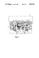
- FIG. 1 is a plan view, partially in phantom line, of a duplex safety electrical receptacle embodying the present invention
- FIG. 2 is a fragmentary, exploded assembly view, partially broken away, of the safety electrical receptacle of FIG. 1;
- FIGS. 3 through 7 are a series of like sectional views illustrating the operation of the safety electrical receptacle of FIG. 1.
- FIG. 1 The present invention is illustrated in FIG. 1 in one of its embodiments as a duplex safety electrical receptacle, generally indicated at 10, having a pair of plug receptacles, generally indicated at 10A and 10B.
- the various parts of the duplex receptacle are conventionally contained within or mounted to a body 12, fragmentarily illustrated in FIG. 3, including line and neutral plug-in contacts, diagrammatically illustrated at 14 and 16, respectively (assuming the receptacle is wired properly).
- a cover, generally indicated at 18, is secured to the base by a screw 19, as seen in FIG. 1.
- the front wall 20 of cover 18 is formed with a rectangular-shaped slot 22, a T-shaped slot 24, and a D-shaped slot 26, as illustrated in FIGS.
- slot 22 is aligned with the line plug-in contacts 14, slot 24 is aligned with the neutral plug-in contacts 16, and slot 26 is aligned with ground plug-in contacts (not shown).
- slot 22 accepts the insertion of one blade 28, and slot 24 accepts a second blade which is either parallel to blade 28, as illustrated at 30, or orthogonal to blade 28, as indicated in phantom at 30a, and slot 26 accepts insertion of a prong, if present.
- These blade configurations represent the various types of standard electrical plugs (polarized and non-polarized, two and three bladed), a low voltage receptacle can encounter in service.
- a shutter mechanism is incorporated in cover 18 intermediate its front wall 20 and body 12.
- This shutter mechanism includes, as best seen in FIG 2, a primary slide, generally indicated at 34, a retainer, generally indicated at 36, a secondary slide, generally indicated at 38, a primary slide compression spring 40 and a secondary slide compression spring 42.
- Edge portions of retainer 36 are seated on internal ledges 44 formed in cover 18 to establish its position, and the retainer is clamped in place between the cover and base by uniting screw 19.
- the retainer is apertured, as indicated at 46, so as not to obstruct access to receptacle contacts 14 and 16.
- Primary slide 34 is supported immediately behind cover front wall 20 by a platform surface 48 of retainer 36 and is guided by opposed internal cover surfaces 50 for reciprocating movement in the directions indicated by arrow 51 between extreme open and closed-latched positions and a range of intermediate closed (unlatched) positions.
- Secondary slide 38 is also supported immediately behind the cover front wall by the retainer on a separate platform surface 52 and is guided by internal coversurfaces 54 and retainer edges 52a (FIG. 2) for reciprocating movement in the direction indicated by arrow 55 between open and closed positions.
- receptacle 10A is illustrated with its slides 34, 38 in their spring-biased closed-latched, blade insertion blocking positions
- receptacle 10B is illustrated with its slides in their open, blade insertion unblocking positions.
- Spring 40 accommodated in the slide open interior 59, acts between a cover depending abutment 56 and a surface 57 of primary slide 34 to bias this slide to its closed-latched position.
- An upstanding retainer tab 53 serves to maintain the spring end positioned against abutment 56.
- Spring 42 backed by cover depending abutment 58 (FIG. 1) biases secondary slide 38 to its closed position.
- primary slide 34 is provided with a ramp 74 disposed immediately behind the portion 24a of T-shaped slot 24 oriented in parallel relation to slot 22.
- the surface of this ramp is sloped such that the insert of an object through slot portion24a into engagement with the ramp exerts a force on the primary slide in a direction toward its open position.
- the primary slide can not be moved away from its closed position by the insertion of a foreign object through slot portion 24a.
- primary slide 34 can be shifted from its closed-latchedposition to its open position only in response to the insertions of blade-like objects into slots 22 and 24 concurrently, such as occur when astandard electrical plug is normally inserted into either receptacle 10A, 10B.
- FIG. 4 illustrates this event.
- the former first engages nose 62 before the latter engages ramp 74.
- the nose is more elevated than the ramp by virtue of spring 40 having rocked primary slide 34 on fulcrums 60 counterclockwise to its closed-latched position seen in FIG. 3.
- the initial engagement of blade 28 with nose 62 rocks primary slide 34 about its fulcrums in the clockwise direction to the closed (unlatched) positionseen in FIG. 4.
- blade 30 engages ramp74, camming primary slide 34 rightwardly toward its open position, as illustrated in FIG. 5.
- ledge 64 continues to block direct accessto plug-in contacts 14, which are the live contacts assuming the receptacleis properly wired.
- plug-in contacts 14 are the live contacts assuming the receptacleis properly wired.
- the primary slide is still in a closed-unlatched position. It is only until the primary slide is shifted completely to its open position by the penetration of blade 30 that ledge 64 fully uncovers contacts 14 to allow blade 28 to penetrate the slide interior opening 59 (FIG. 2) into plug-in engagement with these contacts, as illustrated in FIG. 6.
- FIG. 7 illustrates the situation when a foreign object 29 is inserted through slot 22.
- Nose 62 is readily depressed to unlatch primary slide andcan be forced aside to permit further penetration as the primary slide is incrementally shifted rightward.
- the primary slide is still in a closed, albeit unlatched position, and ledge 64 remains in blocking relation with contacts 14 to prevent continued penetration of the foreign object into contact therewith.
- FIG. 3 it will be appreciated from FIG. 3 that thespurious insertion of a foreign object through slot 24 is blocked by ramp 74, and, since the primary slide is in its closed-latched position, it cannot be cammed rightward to its open position. Thus, access to plug-in contacts 16 is denied, which contacts would be live if the receptacle is not wired in accordance with convention.
- this secondary slide is supported by retainer 36 and guided by both cover 18 and the retainer for reciprocatingmovement between open and closed positions along a path (arrow 55) which isnormal to the primary slide reciprocating path (arrow 51) as seen in FIG. 1.
- Secondary slide is formed having a ramp surface 80 (FIGS. 1 and 2) and a latching tab 82. With the secondary slide raised to its closed position by spring 42, ramp surface 80 is situated behind the portion 24b of T-shaped slot 24, and tab 82 is lodged in a notch 84 formed in ramp 74 of primary slide 34 while in its closed-latched position. Thus, the secondaryslide is latched in its closed-latched position as long as the primary slide is in its closed-latched position.
Abstract
Description
Claims (20)
Priority Applications (1)
| Application Number | Priority Date | Filing Date | Title |
|---|---|---|---|
| US07/226,653 US4867694A (en) | 1988-08-01 | 1988-08-01 | Safety electrical receptacle |
Applications Claiming Priority (1)
| Application Number | Priority Date | Filing Date | Title |
|---|---|---|---|
| US07/226,653 US4867694A (en) | 1988-08-01 | 1988-08-01 | Safety electrical receptacle |
Publications (1)
| Publication Number | Publication Date |
|---|---|
| US4867694A true US4867694A (en) | 1989-09-19 |
Family
ID=22849831
Family Applications (1)
| Application Number | Title | Priority Date | Filing Date |
|---|---|---|---|
| US07/226,653 Expired - Lifetime US4867694A (en) | 1988-08-01 | 1988-08-01 | Safety electrical receptacle |
Country Status (1)
| Country | Link |
|---|---|
| US (1) | US4867694A (en) |
Cited By (69)
| Publication number | Priority date | Publication date | Assignee | Title |
|---|---|---|---|---|
| US5006075A (en) * | 1989-02-09 | 1991-04-09 | Pass & Seymour, Inc. | Electrical receptacle with shuttered prong-receiving openings |
| US5020997A (en) * | 1989-07-05 | 1991-06-04 | Bticino S.R.L. | Safety device for shielding off the receptacles of an electric current tap |
| US5391085A (en) * | 1993-06-24 | 1995-02-21 | Tigner; Alexander B. | Electrical socket assembly including safety device |
| US5702259A (en) * | 1996-08-12 | 1997-12-30 | Lee; Chiu-Shan | Safety socket and plug arrangement |
| US5727958A (en) * | 1996-08-12 | 1998-03-17 | Chen; Chien-Ming | Slidable spring actuated guard lid for household socket set |
| US5839909A (en) * | 1996-07-30 | 1998-11-24 | Bticino, S.P.A. | Shutter device for closing off the compartments of a power socket |
| US5915981A (en) * | 1996-06-17 | 1999-06-29 | Pass & Seymour, Inc. | Electrical receptacle with safety shutter |
| US5967815A (en) | 1998-03-19 | 1999-10-19 | Marc A. Schlessinger | Variable orientation switching type electrical receptacle |
| US6056564A (en) * | 1999-04-07 | 2000-05-02 | Huang; Chun-Hao | Safety receptacle structure |
| USD429694S (en) | 1998-09-11 | 2000-08-22 | Marc A. Schlessinger | Housing and bracket portions of an electrical receptacle |
| US6149446A (en) * | 1999-12-02 | 2000-11-21 | Yu; Tsung-I | Safety structure of a three-hole socket |
| US6238224B1 (en) * | 1999-12-02 | 2001-05-29 | Hung-Chiang Shao | Safety structure in a socket |
| EP1258057A1 (en) * | 2000-02-24 | 2002-11-20 | Chang Woo Lee | Concentric plug |
| US6537088B2 (en) * | 2001-07-17 | 2003-03-25 | Atom Technology Inc. | Plug receptacle protection cover containing intermediate flexible element |
| US6537089B1 (en) * | 2001-12-14 | 2003-03-25 | Safer Home, Inc. | Gated electrical safety outlet |
| US20040110402A1 (en) * | 2002-09-30 | 2004-06-10 | Jones Randall T. | Electrical connector assembly |
| WO2004067891A2 (en) * | 2003-01-29 | 2004-08-12 | Koncept Technologies Inc. | Shutter assembly for receptacle |
| US6776630B1 (en) * | 2003-10-06 | 2004-08-17 | Atom Technology Inc. | Safety socket protective cover |
| US6786745B1 (en) * | 2003-08-18 | 2004-09-07 | Chyong-Yen Huang | Safety protective cover for socket receptacles |
| US20050026482A1 (en) * | 2003-07-28 | 2005-02-03 | Chyong-Yen Huang | Socket protective cover capable of preventing single-opening insertion |
| US6935874B1 (en) * | 2004-03-12 | 2005-08-30 | Tsann Kuen Enterprise Co., Ltd. | Cooking assembly with a safety device |
| US7045723B1 (en) | 2005-09-27 | 2006-05-16 | Joti Projkovski | Fail safe electrical receptacle |
| US7179992B1 (en) | 2003-08-21 | 2007-02-20 | Pass & Seymour, Inc. | Device with tamper resistant shutters |
| US20070111569A1 (en) * | 2005-10-31 | 2007-05-17 | Frantz Germain | Tamper proof gfci |
| US20070114053A1 (en) * | 2005-09-08 | 2007-05-24 | Cosmo Castaldo | Tamper-resistant electrical wiring device system |
| US20070211397A1 (en) * | 2006-02-10 | 2007-09-13 | Stephen Sokolow | Tamper resistant ground fault circuit interrupter receptacle having dual function shutters |
| US7312963B1 (en) * | 2003-12-05 | 2007-12-25 | Pass & Seymour, Inc. | Protective device with tamper resistant shutters |
| US20080156512A1 (en) * | 2005-09-08 | 2008-07-03 | Cosmo Castaldo | Tamper-resistant electrical wiring device system |
| US20080194128A1 (en) * | 2007-02-12 | 2008-08-14 | Koncept Technologies Inc. | Compact shutter assembly for receptacle |
| US7414499B2 (en) | 2004-04-08 | 2008-08-19 | Leviton Manufacturing Co., Inc. | Circuit interrupting device with a single test-reset button |
| US20080248662A1 (en) * | 2006-02-10 | 2008-10-09 | Leviton Manufacturing Co., Inc. | Tamper resistant interrupter receptacle having a detachable metal skin |
| US7439833B2 (en) | 2002-12-30 | 2008-10-21 | Leviton Manufacturing Co., Ltd. | Ground fault circuit interrupter with blocking member |
| US7455538B2 (en) | 2005-08-31 | 2008-11-25 | Leviton Manufacturing Co., Inc. | Electrical wiring devices with a protective shutter |
| US7492558B2 (en) | 2000-10-16 | 2009-02-17 | Leviton Manufacturing Co., Inc. | Reset lockout for sliding latch GFCI |
| US7517235B2 (en) | 2006-12-28 | 2009-04-14 | General Electric Company | Press fit connection for mounting electrical plug-in outlet insulator to a busway aluminum housing |
| US20090227131A1 (en) * | 2008-03-07 | 2009-09-10 | Carbone Christopher A | Tamper resistant assembly for an electrical receptacle |
| US20090227130A1 (en) * | 2008-03-07 | 2009-09-10 | Carbone Christopher A | Tamper resistant assembly for an electrical receptacle |
| US7588447B1 (en) * | 2008-03-18 | 2009-09-15 | Wenzhou Mtlc Electrical Appliances Co., Ltd. | Safety receptacle with tamper resistant shutter |
| US20090236115A1 (en) * | 2008-01-29 | 2009-09-24 | Shanghai Ele Manufacturing Corp. | Tamper resistant power receptacle having a safety shutter |
| US20090311892A1 (en) * | 2003-12-05 | 2009-12-17 | Pass & Seymour, Inc. | Protective device with tamper resistant shutters |
| US7637756B1 (en) * | 2008-09-08 | 2009-12-29 | Powertech Industrial Co., Ltd. | Socket safety apparatus |
| US7695293B1 (en) * | 2009-02-16 | 2010-04-13 | Sikes Dwight D | Childproof electrical outlet covering system |
| US7737809B2 (en) | 2003-02-03 | 2010-06-15 | Leviton Manufacturing Co., Inc. | Circuit interrupting device and system utilizing bridge contact mechanism and reset lockout |
| FR2945893A1 (en) * | 2009-05-25 | 2010-11-26 | Legrand France | Power socket for receiving electrical plug, has security lock occupying locking and releasing positions and formed from piece distinct from metallic strip of earth pin, where piece is movably mounted at back of trimming cover |
| US7887349B1 (en) | 2009-09-09 | 2011-02-15 | Breacher Boys, Llc | Safety electrical receptacle |
| CN101980404A (en) * | 2010-11-26 | 2011-02-23 | 浙江正泰建筑电器有限公司 | Bipolar socket protection door |
| US7907371B2 (en) | 1998-08-24 | 2011-03-15 | Leviton Manufacturing Company, Inc. | Circuit interrupting device with reset lockout and reverse wiring protection and method of manufacture |
| US20110104919A1 (en) * | 2009-10-30 | 2011-05-05 | Leviton Mfg. Co. | Receptacle with antenna |
| US20120083143A1 (en) * | 2010-09-30 | 2012-04-05 | General Protecht Group, Inc. | Supported slide safety member for a low voltage power connection device |
| US20120149221A1 (en) * | 2010-09-30 | 2012-06-14 | Huadao Huang | Power Outlet with Jack Safety Shield Device |
| US8435055B1 (en) | 2011-10-26 | 2013-05-07 | Leviton Manufacturing Co., Inc. | Tamper resistant electrical wiring device system |
| US8444309B2 (en) | 2010-08-13 | 2013-05-21 | Leviton Manufacturing Company, Inc. | Wiring device with illumination |
| US20130280573A1 (en) * | 2010-11-12 | 2013-10-24 | Makita Corporation | Battery pack |
| US8568152B1 (en) | 2012-04-19 | 2013-10-29 | Pass & Seymour, Inc. | Shutter assembly for electrical devices |
| US8737025B2 (en) | 2003-01-09 | 2014-05-27 | Pass & Seymour, Inc. | Protective electrical wiring device with tamper resistant shutters |
| CN104377518A (en) * | 2013-07-10 | 2015-02-25 | 沃尔特·拉夫纳 | Multiple plug socket |
| US9048559B2 (en) | 2011-05-12 | 2015-06-02 | Huadao Huang | Power outlet with jack safety shield device |
| US9059530B2 (en) | 2013-07-30 | 2015-06-16 | Norman R. Byrne | Access-restricted electrical receptacle |
| US20150372411A1 (en) * | 2014-06-20 | 2015-12-24 | Hubbell Incorporated | Tamper resistant receptacle shutter with friction reducing lead in configuration |
| US20150380856A1 (en) * | 2014-06-20 | 2015-12-31 | Hubbell Incorporated | Tamper resistant receptacle |
| US20160104961A1 (en) * | 2014-10-14 | 2016-04-14 | Pass & Seymour, Inc. | Electrical Wiring Device with Shutters |
| US10096929B2 (en) * | 2016-03-25 | 2018-10-09 | Powertech Industrial Co., Ltd. | Safety socket device |
| US10559909B1 (en) * | 2019-03-04 | 2020-02-11 | Leviton Manufacturing Co., Inc. | Tamper resistant electrical receptacle |
| USD912628S1 (en) | 2017-12-05 | 2021-03-09 | Arconas Corporation | Power receptacle |
| GB2588712A (en) * | 2019-09-30 | 2021-05-05 | Schneider Electric Australia Pty Ltd | Socket |
| US11011877B2 (en) | 2015-03-05 | 2021-05-18 | Vernon R. Sandel | Tamper resistant power receptacle |
| US11108186B2 (en) * | 2019-06-23 | 2021-08-31 | Vernon Ralph Sandel | Internal shutters and lock mechanisms for safety electrical receptacles |
| US11139611B2 (en) | 2019-06-08 | 2021-10-05 | Norman R. Byrne | Electrical receptacle with drain-through feature |
| US11431137B2 (en) | 2021-01-08 | 2022-08-30 | II Stephen Saxon Fuller | Electrical outlet with safety feature |
Citations (26)
| Publication number | Priority date | Publication date | Assignee | Title |
|---|---|---|---|---|
| CH230573A (en) * | 1942-11-04 | 1944-01-15 | Corrodi Jakob | Socket with safety device. |
| CH239441A (en) * | 1943-09-09 | 1945-10-15 | Leutenegger Friedrich | Electrical plug-in device with a protective device against danger to persons. |
| US2545536A (en) * | 1948-10-15 | 1951-03-20 | Hubbell Inc Harvey | Electrical receptacle with safety closure |
| DE751236C (en) * | 1938-02-17 | 1953-02-23 | Kostal Fa Leopold | Touchproof socket outlet |
| US2770786A (en) * | 1952-10-11 | 1956-11-13 | Chelton Mac Victor | Double safety electrical receptacle |
| FR1311993A (en) * | 1961-11-02 | 1962-12-14 | Arnould Ets | Improvements to multipolar sockets |
| US3222631A (en) * | 1963-12-24 | 1965-12-07 | Leonard A Cohen | Electrical socket |
| FR1425461A (en) * | 1964-12-08 | 1966-01-24 | Comp Generale Electricite | Improvements to sockets |
| US3238492A (en) * | 1964-01-16 | 1966-03-01 | Hubbell Inc Harvey | Safety electric receptacle |
| FR1448863A (en) * | 1965-06-08 | 1966-08-12 | Safety electrical outlet | |
| DE1440799A1 (en) * | 1962-11-29 | 1968-11-21 | Berker Geb | Safety socket |
| DE1465128A1 (en) * | 1963-12-09 | 1969-01-23 | Eljo Plastindustri Ab | Protective device, preferably on electrical connections |
| SE314729B (en) * | 1967-04-11 | 1969-09-15 | Eljo Plastindustri Ab | Two-pole socket with locking through two flaps |
| DE2038508A1 (en) * | 1969-09-08 | 1971-03-18 | Feller Ag Adolf | Electrical safety socket |
| DE2434577A1 (en) * | 1974-07-18 | 1976-01-29 | Giersiepen Eltech Ind | Three-pin socket with protected plug-in holes - has reduced size sliding plate with wedged areas on crossbars moved aside by pins on plug |
| DE2434578A1 (en) * | 1974-07-18 | 1976-01-29 | Giersiepen Eltech Ind | Two-pin socket and plug connector - with protected access holes uses internal sliding plate with wedged area on crossbars for size reduction |
| US3986763A (en) * | 1975-10-15 | 1976-10-19 | Midland Electric Manufacturing Company | Electric sockets |
| US3990758A (en) * | 1974-05-06 | 1976-11-09 | Petterson Tor H | Child-safe electrical outlet |
| US4072382A (en) * | 1976-06-02 | 1978-02-07 | Reschke Kurt W | Safety outlet |
| US4094569A (en) * | 1977-05-09 | 1978-06-13 | Pacific Electricord Company | Safety cap slide |
| US4168104A (en) * | 1978-06-29 | 1979-09-18 | Buschow Dean W | Electrical receptacle |
| GB1585094A (en) * | 1977-05-13 | 1981-02-25 | Tenby Elect Accessories Ltd | Electrical sockets |
| US4379607A (en) * | 1980-10-06 | 1983-04-12 | Slater Electric Inc. | Shuttered receptacle |
| US4544219A (en) * | 1984-06-01 | 1985-10-01 | Harvey Hubbell Incorporated | Shuttered electrical receptacle |
| US4722693A (en) * | 1987-03-30 | 1988-02-02 | Friedhelm Rose | Safety shutters for electrical receptacles |
| US4822290A (en) * | 1986-05-30 | 1989-04-18 | Cauley William J | Electric receptacle |
-
1988
- 1988-08-01 US US07/226,653 patent/US4867694A/en not_active Expired - Lifetime
Patent Citations (26)
| Publication number | Priority date | Publication date | Assignee | Title |
|---|---|---|---|---|
| DE751236C (en) * | 1938-02-17 | 1953-02-23 | Kostal Fa Leopold | Touchproof socket outlet |
| CH230573A (en) * | 1942-11-04 | 1944-01-15 | Corrodi Jakob | Socket with safety device. |
| CH239441A (en) * | 1943-09-09 | 1945-10-15 | Leutenegger Friedrich | Electrical plug-in device with a protective device against danger to persons. |
| US2545536A (en) * | 1948-10-15 | 1951-03-20 | Hubbell Inc Harvey | Electrical receptacle with safety closure |
| US2770786A (en) * | 1952-10-11 | 1956-11-13 | Chelton Mac Victor | Double safety electrical receptacle |
| FR1311993A (en) * | 1961-11-02 | 1962-12-14 | Arnould Ets | Improvements to multipolar sockets |
| DE1440799A1 (en) * | 1962-11-29 | 1968-11-21 | Berker Geb | Safety socket |
| DE1465128A1 (en) * | 1963-12-09 | 1969-01-23 | Eljo Plastindustri Ab | Protective device, preferably on electrical connections |
| US3222631A (en) * | 1963-12-24 | 1965-12-07 | Leonard A Cohen | Electrical socket |
| US3238492A (en) * | 1964-01-16 | 1966-03-01 | Hubbell Inc Harvey | Safety electric receptacle |
| FR1425461A (en) * | 1964-12-08 | 1966-01-24 | Comp Generale Electricite | Improvements to sockets |
| FR1448863A (en) * | 1965-06-08 | 1966-08-12 | Safety electrical outlet | |
| SE314729B (en) * | 1967-04-11 | 1969-09-15 | Eljo Plastindustri Ab | Two-pole socket with locking through two flaps |
| DE2038508A1 (en) * | 1969-09-08 | 1971-03-18 | Feller Ag Adolf | Electrical safety socket |
| US3990758A (en) * | 1974-05-06 | 1976-11-09 | Petterson Tor H | Child-safe electrical outlet |
| DE2434577A1 (en) * | 1974-07-18 | 1976-01-29 | Giersiepen Eltech Ind | Three-pin socket with protected plug-in holes - has reduced size sliding plate with wedged areas on crossbars moved aside by pins on plug |
| DE2434578A1 (en) * | 1974-07-18 | 1976-01-29 | Giersiepen Eltech Ind | Two-pin socket and plug connector - with protected access holes uses internal sliding plate with wedged area on crossbars for size reduction |
| US3986763A (en) * | 1975-10-15 | 1976-10-19 | Midland Electric Manufacturing Company | Electric sockets |
| US4072382A (en) * | 1976-06-02 | 1978-02-07 | Reschke Kurt W | Safety outlet |
| US4094569A (en) * | 1977-05-09 | 1978-06-13 | Pacific Electricord Company | Safety cap slide |
| GB1585094A (en) * | 1977-05-13 | 1981-02-25 | Tenby Elect Accessories Ltd | Electrical sockets |
| US4168104A (en) * | 1978-06-29 | 1979-09-18 | Buschow Dean W | Electrical receptacle |
| US4379607A (en) * | 1980-10-06 | 1983-04-12 | Slater Electric Inc. | Shuttered receptacle |
| US4544219A (en) * | 1984-06-01 | 1985-10-01 | Harvey Hubbell Incorporated | Shuttered electrical receptacle |
| US4822290A (en) * | 1986-05-30 | 1989-04-18 | Cauley William J | Electric receptacle |
| US4722693A (en) * | 1987-03-30 | 1988-02-02 | Friedhelm Rose | Safety shutters for electrical receptacles |
Cited By (109)
| Publication number | Priority date | Publication date | Assignee | Title |
|---|---|---|---|---|
| US5006075A (en) * | 1989-02-09 | 1991-04-09 | Pass & Seymour, Inc. | Electrical receptacle with shuttered prong-receiving openings |
| US5020997A (en) * | 1989-07-05 | 1991-06-04 | Bticino S.R.L. | Safety device for shielding off the receptacles of an electric current tap |
| US5391085A (en) * | 1993-06-24 | 1995-02-21 | Tigner; Alexander B. | Electrical socket assembly including safety device |
| US5915981A (en) * | 1996-06-17 | 1999-06-29 | Pass & Seymour, Inc. | Electrical receptacle with safety shutter |
| US5839909A (en) * | 1996-07-30 | 1998-11-24 | Bticino, S.P.A. | Shutter device for closing off the compartments of a power socket |
| CN1098545C (en) * | 1996-07-30 | 2003-01-08 | 布蒂克诺公司 | Shutter device for closing off compartments of power socket |
| US5702259A (en) * | 1996-08-12 | 1997-12-30 | Lee; Chiu-Shan | Safety socket and plug arrangement |
| US5727958A (en) * | 1996-08-12 | 1998-03-17 | Chen; Chien-Ming | Slidable spring actuated guard lid for household socket set |
| US5967815A (en) | 1998-03-19 | 1999-10-19 | Marc A. Schlessinger | Variable orientation switching type electrical receptacle |
| US7907371B2 (en) | 1998-08-24 | 2011-03-15 | Leviton Manufacturing Company, Inc. | Circuit interrupting device with reset lockout and reverse wiring protection and method of manufacture |
| US8054595B2 (en) | 1998-08-24 | 2011-11-08 | Leviton Manufacturing Co., Inc. | Circuit interrupting device with reset lockout |
| US8130480B2 (en) | 1998-08-24 | 2012-03-06 | Leviton Manufactuing Co., Inc. | Circuit interrupting device with reset lockout |
| USD429694S (en) | 1998-09-11 | 2000-08-22 | Marc A. Schlessinger | Housing and bracket portions of an electrical receptacle |
| US6056564A (en) * | 1999-04-07 | 2000-05-02 | Huang; Chun-Hao | Safety receptacle structure |
| US6149446A (en) * | 1999-12-02 | 2000-11-21 | Yu; Tsung-I | Safety structure of a three-hole socket |
| US6238224B1 (en) * | 1999-12-02 | 2001-05-29 | Hung-Chiang Shao | Safety structure in a socket |
| EP1258057A4 (en) * | 2000-02-24 | 2003-12-03 | Chang Woo Lee | Concentric plug |
| EP1258057A1 (en) * | 2000-02-24 | 2002-11-20 | Chang Woo Lee | Concentric plug |
| US6786744B1 (en) * | 2000-02-24 | 2004-09-07 | Chang Woo Lee | Concentric plug |
| US8004804B2 (en) | 2000-10-16 | 2011-08-23 | Leviton Manufacturing Co., Inc. | Circuit interrupter having at least one indicator |
| US7492558B2 (en) | 2000-10-16 | 2009-02-17 | Leviton Manufacturing Co., Inc. | Reset lockout for sliding latch GFCI |
| US6537088B2 (en) * | 2001-07-17 | 2003-03-25 | Atom Technology Inc. | Plug receptacle protection cover containing intermediate flexible element |
| US6537089B1 (en) * | 2001-12-14 | 2003-03-25 | Safer Home, Inc. | Gated electrical safety outlet |
| US6835076B2 (en) * | 2002-09-30 | 2004-12-28 | Delphi Technologies, Inc. | Electrical connector assembly |
| US20040110402A1 (en) * | 2002-09-30 | 2004-06-10 | Jones Randall T. | Electrical connector assembly |
| US7439833B2 (en) | 2002-12-30 | 2008-10-21 | Leviton Manufacturing Co., Ltd. | Ground fault circuit interrupter with blocking member |
| US8737025B2 (en) | 2003-01-09 | 2014-05-27 | Pass & Seymour, Inc. | Protective electrical wiring device with tamper resistant shutters |
| WO2004067891A3 (en) * | 2003-01-29 | 2005-03-31 | Koncept Technologies Inc | Shutter assembly for receptacle |
| US6893275B2 (en) * | 2003-01-29 | 2005-05-17 | Koncept Technologies Inc. | Electrical receptacle with shutter |
| WO2004067891A2 (en) * | 2003-01-29 | 2004-08-12 | Koncept Technologies Inc. | Shutter assembly for receptacle |
| US7737809B2 (en) | 2003-02-03 | 2010-06-15 | Leviton Manufacturing Co., Inc. | Circuit interrupting device and system utilizing bridge contact mechanism and reset lockout |
| US20050026482A1 (en) * | 2003-07-28 | 2005-02-03 | Chyong-Yen Huang | Socket protective cover capable of preventing single-opening insertion |
| US6932631B2 (en) * | 2003-07-28 | 2005-08-23 | Atom Technology Inc. | Socket protective cover capable of preventing single-opening insertion |
| US6786745B1 (en) * | 2003-08-18 | 2004-09-07 | Chyong-Yen Huang | Safety protective cover for socket receptacles |
| US7179992B1 (en) | 2003-08-21 | 2007-02-20 | Pass & Seymour, Inc. | Device with tamper resistant shutters |
| US6776630B1 (en) * | 2003-10-06 | 2004-08-17 | Atom Technology Inc. | Safety socket protective cover |
| US7312963B1 (en) * | 2003-12-05 | 2007-12-25 | Pass & Seymour, Inc. | Protective device with tamper resistant shutters |
| US8044299B2 (en) | 2003-12-05 | 2011-10-25 | Pass & Seymour, Inc. | Protective device with tamper resistant shutters |
| US7642457B2 (en) | 2003-12-05 | 2010-01-05 | Pass & Seymour, Inc. | Protective device with tamper resistant shutters |
| US20090311892A1 (en) * | 2003-12-05 | 2009-12-17 | Pass & Seymour, Inc. | Protective device with tamper resistant shutters |
| US20090052120A1 (en) * | 2003-12-05 | 2009-02-26 | Pass & Seymour, Inc. | Protective Device with Tamper Resistant Shutters |
| US6935874B1 (en) * | 2004-03-12 | 2005-08-30 | Tsann Kuen Enterprise Co., Ltd. | Cooking assembly with a safety device |
| US20050202699A1 (en) * | 2004-03-12 | 2005-09-15 | Chih-Cheng Fang | Cooking assembly with a safety device |
| US7414499B2 (en) | 2004-04-08 | 2008-08-19 | Leviton Manufacturing Co., Inc. | Circuit interrupting device with a single test-reset button |
| US7455538B2 (en) | 2005-08-31 | 2008-11-25 | Leviton Manufacturing Co., Inc. | Electrical wiring devices with a protective shutter |
| US7355117B2 (en) | 2005-09-08 | 2008-04-08 | Leviton Manufacturing Co., Inc. | Tamper-resistant electrical wiring device system |
| US7820909B2 (en) | 2005-09-08 | 2010-10-26 | Leviton Manufacturing Co., Inc. | Tamper-resistant electrical wiring device system |
| US8242362B2 (en) | 2005-09-08 | 2012-08-14 | Leviton Manufacturing Co., Inc. | Tamper-resistant electrical wiring device system |
| US20080156512A1 (en) * | 2005-09-08 | 2008-07-03 | Cosmo Castaldo | Tamper-resistant electrical wiring device system |
| US20110028011A1 (en) * | 2005-09-08 | 2011-02-03 | Leviton Manufacturing Co., Inc. | Tamper-resistant electrical wiring device system |
| US20070114053A1 (en) * | 2005-09-08 | 2007-05-24 | Cosmo Castaldo | Tamper-resistant electrical wiring device system |
| US7045723B1 (en) | 2005-09-27 | 2006-05-16 | Joti Projkovski | Fail safe electrical receptacle |
| US20070111569A1 (en) * | 2005-10-31 | 2007-05-17 | Frantz Germain | Tamper proof gfci |
| US7651347B2 (en) | 2005-10-31 | 2010-01-26 | Leviton Manufacturing Co., Inc. | Tamper resistant mechanism with circuit interrupter |
| US20080248662A1 (en) * | 2006-02-10 | 2008-10-09 | Leviton Manufacturing Co., Inc. | Tamper resistant interrupter receptacle having a detachable metal skin |
| US7551047B2 (en) * | 2006-02-10 | 2009-06-23 | Leviton Manufacturing Co., Inc. | Tamper resistant ground fault circuit interrupter receptacle having dual function shutters |
| US20090286411A1 (en) * | 2006-02-10 | 2009-11-19 | Leviton Manufacturing Co. Inc. | Tamper resistant interrupter receptacle having a detachable metal skin |
| US20070211397A1 (en) * | 2006-02-10 | 2007-09-13 | Stephen Sokolow | Tamper resistant ground fault circuit interrupter receptacle having dual function shutters |
| US7868719B2 (en) * | 2006-02-10 | 2011-01-11 | Leviton Manufacturing Co., Inc. | Tamper resistant interrupter receptacle having a detachable metal skin |
| US7517235B2 (en) | 2006-12-28 | 2009-04-14 | General Electric Company | Press fit connection for mounting electrical plug-in outlet insulator to a busway aluminum housing |
| US20080194128A1 (en) * | 2007-02-12 | 2008-08-14 | Koncept Technologies Inc. | Compact shutter assembly for receptacle |
| US7556513B2 (en) | 2007-02-12 | 2009-07-07 | Koncept Technologies Inc. | Compact shutter assembly for receptacle |
| US20090236115A1 (en) * | 2008-01-29 | 2009-09-24 | Shanghai Ele Manufacturing Corp. | Tamper resistant power receptacle having a safety shutter |
| US8193445B2 (en) | 2008-01-29 | 2012-06-05 | Bingham McCutchen LLP | Tamper resistant power receptacle having a safety shutter |
| US7645149B2 (en) | 2008-03-07 | 2010-01-12 | Hubbell Incorporated | Tamper resistant assembly for an electrical receptacle |
| US20090227131A1 (en) * | 2008-03-07 | 2009-09-10 | Carbone Christopher A | Tamper resistant assembly for an electrical receptacle |
| US20090227130A1 (en) * | 2008-03-07 | 2009-09-10 | Carbone Christopher A | Tamper resistant assembly for an electrical receptacle |
| US7645148B2 (en) * | 2008-03-07 | 2010-01-12 | Hubbell Incorporated | Tamper resistant assembly for an electrical receptacle |
| US20090239400A1 (en) * | 2008-03-18 | 2009-09-24 | Wenzhou Mtlc Electrical Appliances Co., Ltd. | Safety receptacle with tamper resistant shutter |
| US7588447B1 (en) * | 2008-03-18 | 2009-09-15 | Wenzhou Mtlc Electrical Appliances Co., Ltd. | Safety receptacle with tamper resistant shutter |
| US7637756B1 (en) * | 2008-09-08 | 2009-12-29 | Powertech Industrial Co., Ltd. | Socket safety apparatus |
| US7695293B1 (en) * | 2009-02-16 | 2010-04-13 | Sikes Dwight D | Childproof electrical outlet covering system |
| FR2945893A1 (en) * | 2009-05-25 | 2010-11-26 | Legrand France | Power socket for receiving electrical plug, has security lock occupying locking and releasing positions and formed from piece distinct from metallic strip of earth pin, where piece is movably mounted at back of trimming cover |
| US7887349B1 (en) | 2009-09-09 | 2011-02-15 | Breacher Boys, Llc | Safety electrical receptacle |
| US20110205135A1 (en) * | 2009-10-30 | 2011-08-25 | Leviton Mfg. Co. | Receptacle with antenna |
| US7938676B1 (en) | 2009-10-30 | 2011-05-10 | Leviton Mfg. Co. | Receptacle with antenna |
| US20110104919A1 (en) * | 2009-10-30 | 2011-05-05 | Leviton Mfg. Co. | Receptacle with antenna |
| US8105094B2 (en) | 2009-10-30 | 2012-01-31 | Leviton Mfg. Co. | Receptacle with antenna |
| US8444309B2 (en) | 2010-08-13 | 2013-05-21 | Leviton Manufacturing Company, Inc. | Wiring device with illumination |
| US20120149221A1 (en) * | 2010-09-30 | 2012-06-14 | Huadao Huang | Power Outlet with Jack Safety Shield Device |
| US8550829B2 (en) * | 2010-09-30 | 2013-10-08 | Huadao Huang | Power outlet with jack safety shield device |
| US8562362B2 (en) * | 2010-09-30 | 2013-10-22 | Heng Chen | Supported slide safety member for a low voltage power connection device |
| US20120083143A1 (en) * | 2010-09-30 | 2012-04-05 | General Protecht Group, Inc. | Supported slide safety member for a low voltage power connection device |
| US20130280573A1 (en) * | 2010-11-12 | 2013-10-24 | Makita Corporation | Battery pack |
| US9368765B2 (en) * | 2010-11-12 | 2016-06-14 | Makita Corporation | Battery pack |
| CN101980404A (en) * | 2010-11-26 | 2011-02-23 | 浙江正泰建筑电器有限公司 | Bipolar socket protection door |
| US9048559B2 (en) | 2011-05-12 | 2015-06-02 | Huadao Huang | Power outlet with jack safety shield device |
| US8435055B1 (en) | 2011-10-26 | 2013-05-07 | Leviton Manufacturing Co., Inc. | Tamper resistant electrical wiring device system |
| US8568152B1 (en) | 2012-04-19 | 2013-10-29 | Pass & Seymour, Inc. | Shutter assembly for electrical devices |
| CN104377518A (en) * | 2013-07-10 | 2015-02-25 | 沃尔特·拉夫纳 | Multiple plug socket |
| US9281602B2 (en) * | 2013-07-10 | 2016-03-08 | Walter Ruffner | Multiple socket |
| CN104377518B (en) * | 2013-07-10 | 2018-11-06 | 沃尔特·拉夫纳 | Multiple socket |
| US20150099380A1 (en) * | 2013-07-10 | 2015-04-09 | Walter Ruffner | Multiple socket |
| US9059530B2 (en) | 2013-07-30 | 2015-06-16 | Norman R. Byrne | Access-restricted electrical receptacle |
| US20150372411A1 (en) * | 2014-06-20 | 2015-12-24 | Hubbell Incorporated | Tamper resistant receptacle shutter with friction reducing lead in configuration |
| US20150380856A1 (en) * | 2014-06-20 | 2015-12-31 | Hubbell Incorporated | Tamper resistant receptacle |
| US9502807B2 (en) * | 2014-06-20 | 2016-11-22 | Hubbell Incorporated | Tamper resistant receptacle |
| US9502806B2 (en) * | 2014-06-20 | 2016-11-22 | Hubbell Incorporated | Tamper resistant receptacle shutter with friction reducing lead in configuration |
| US9847611B2 (en) * | 2014-10-14 | 2017-12-19 | Pass & Seymour, Inc. | Electrical wiring device with shutters |
| US20160104961A1 (en) * | 2014-10-14 | 2016-04-14 | Pass & Seymour, Inc. | Electrical Wiring Device with Shutters |
| US11011877B2 (en) | 2015-03-05 | 2021-05-18 | Vernon R. Sandel | Tamper resistant power receptacle |
| US10096929B2 (en) * | 2016-03-25 | 2018-10-09 | Powertech Industrial Co., Ltd. | Safety socket device |
| USD912628S1 (en) | 2017-12-05 | 2021-03-09 | Arconas Corporation | Power receptacle |
| US10559909B1 (en) * | 2019-03-04 | 2020-02-11 | Leviton Manufacturing Co., Inc. | Tamper resistant electrical receptacle |
| US11139611B2 (en) | 2019-06-08 | 2021-10-05 | Norman R. Byrne | Electrical receptacle with drain-through feature |
| US11108186B2 (en) * | 2019-06-23 | 2021-08-31 | Vernon Ralph Sandel | Internal shutters and lock mechanisms for safety electrical receptacles |
| GB2588712A (en) * | 2019-09-30 | 2021-05-05 | Schneider Electric Australia Pty Ltd | Socket |
| GB2588712B (en) * | 2019-09-30 | 2022-09-07 | Schneider Electric Australia Pty Ltd | Socket with biased protection gate |
| US11431137B2 (en) | 2021-01-08 | 2022-08-30 | II Stephen Saxon Fuller | Electrical outlet with safety feature |
Similar Documents
| Publication | Publication Date | Title |
|---|---|---|
| US4867694A (en) | Safety electrical receptacle | |
| US4867693A (en) | Safety electrical tap | |
| US4822290A (en) | Electric receptacle | |
| US4544219A (en) | Shuttered electrical receptacle | |
| US7452221B1 (en) | Tamper resistant assembly for an electrical receptacle | |
| US5899762A (en) | Electrical connector having an insertion and extraction slide | |
| US7510412B1 (en) | Tamper resistant assembly for an electrical receptacle | |
| US5618195A (en) | Electrical connector incorporating contact-locking grid and drawer | |
| US6394827B2 (en) | Card connector | |
| EP0483853B1 (en) | Connector assembly | |
| EP1180825B1 (en) | Connector | |
| US4932886A (en) | Shockproof electrical outlet | |
| US7214076B1 (en) | Card connector with anti-mismating device | |
| EP0578211B1 (en) | An electrical connector | |
| JP3019280U (en) | IC card holder | |
| EP0338848A2 (en) | Card read/write device | |
| KR950015858A (en) | Electrical connector with terminal position guarantee | |
| US7448886B2 (en) | Card connector with anti-mismating device | |
| US7234966B2 (en) | IC card connector equipped with respective cover doors and associated anti-mismating device | |
| JP4647620B2 (en) | Contact locking device for electrical connector and electrical container containing said device | |
| EP1079474B1 (en) | Scoop-proof plug connector system | |
| US20020001988A1 (en) | Connector | |
| CA1305540C (en) | Safety electrical receptacle | |
| US7090536B2 (en) | IC card connector with anti-mismating device | |
| US5725398A (en) | Electrical connector incorporating contact-locking grid |
Legal Events
| Date | Code | Title | Description |
|---|---|---|---|
| AS | Assignment |
Owner name: GENERAL ELECTRIC COMPANY A NY CORP. Free format text: ASSIGNMENT OF ASSIGNORS INTEREST.;ASSIGNOR:SHORT, STEPHEN P.;REEL/FRAME:004957/0154 Effective date: 19880909 |
|
| FEPP | Fee payment procedure |
Free format text: PAYOR NUMBER ASSIGNED (ORIGINAL EVENT CODE: ASPN); ENTITY STATUS OF PATENT OWNER: LARGE ENTITY |
|
| STCF | Information on status: patent grant |
Free format text: PATENTED CASE |
|
| FEPP | Fee payment procedure |
Free format text: PAYER NUMBER DE-ASSIGNED (ORIGINAL EVENT CODE: RMPN); ENTITY STATUS OF PATENT OWNER: LARGE ENTITY Free format text: PAYOR NUMBER ASSIGNED (ORIGINAL EVENT CODE: ASPN); ENTITY STATUS OF PATENT OWNER: LARGE ENTITY |
|
| FPAY | Fee payment |
Year of fee payment: 4 |
|
| FPAY | Fee payment |
Year of fee payment: 8 |
|
| FPAY | Fee payment |
Year of fee payment: 12 |