US4868476A - Transducer with integral memory - Google Patents
Transducer with integral memory Download PDFInfo
- Publication number
- US4868476A US4868476A US07/115,689 US11568987A US4868476A US 4868476 A US4868476 A US 4868476A US 11568987 A US11568987 A US 11568987A US 4868476 A US4868476 A US 4868476A
- Authority
- US
- United States
- Prior art keywords
- transducer
- transducer element
- scanning
- memory
- information
- Prior art date
- Legal status (The legal status is an assumption and is not a legal conclusion. Google has not performed a legal analysis and makes no representation as to the accuracy of the status listed.)
- Expired - Lifetime
Links
Images

Classifications
-
- G—PHYSICS
- G10—MUSICAL INSTRUMENTS; ACOUSTICS
- G10K—SOUND-PRODUCING DEVICES; METHODS OR DEVICES FOR PROTECTING AGAINST, OR FOR DAMPING, NOISE OR OTHER ACOUSTIC WAVES IN GENERAL; ACOUSTICS NOT OTHERWISE PROVIDED FOR
- G10K11/00—Methods or devices for transmitting, conducting or directing sound in general; Methods or devices for protecting against, or for damping, noise or other acoustic waves in general
- G10K11/18—Methods or devices for transmitting, conducting or directing sound
- G10K11/26—Sound-focusing or directing, e.g. scanning
- G10K11/35—Sound-focusing or directing, e.g. scanning using mechanical steering of transducers or their beams
- G10K11/352—Sound-focusing or directing, e.g. scanning using mechanical steering of transducers or their beams by moving the transducer
- G10K11/355—Arcuate movement
Definitions
- This invention relates to transducers having an integral memory containing selected information concerning the transducer and more particularly to a scanning ultrasonic transducer having an integral memory which stores selected information concerning the transducer which may be utilized in connection with the operation thereof.
- Transducers and in particular ultrasonic transducers, are utilized in many applications, such as medical imaging, where high precision is required. Particularly when the transducers are being used for medical imaging, an error in the positioning of the transducer when readings are being taken could lead to a false diagnosis or treatment.
- FDA regulations also limit the acoustic power output which may be utilized for imaging various areas of the body and various classes of patient such as fetal or infant. Precise control of power output is therefore required, particularly for transducers which are to be used for more than one class of imaging.
- control of transducer position to a selected level of precision has been achieved by maintaining high tolerances in the manufacturing process and by carefully testing and hand-adjusting transducer units which do not conform to these tolerances.
- mechanical scanning transducers typically have a position sensor, the output from which is compared with a reference signal, and the error output from the comparator is utilized to control a servo-motor which moves the transducer through its scan path.
- Any nonlinearity in the position sensing device can result in false position readings and can also cause slight variations in the sweep speed of the transducer. Even when great care and expense are taken in the manufacturing process and in the hand adjustment of the device, it is impossible to eliminate all nonlinearity from the position sensing mechanism. As a result, such transducers have been relatively expensive while still providing less than ideal operation.
- the power output characteristics of individual transducer elements may vary slightly with the applied input, making it difficult, even with high manufacturing tolerances, to provide transducers which produce required acoustic power outputs for different classes of service. Again, even at relatively high cost, less than ideal results are achieved.
- each transducer has various constants and other parameter values which must be known to the system utilizing the transducer in order for the system to properly control the transducer and to properly interpret the results obtained therefrom.
- the system utilizing the transducer has had to store representative values for each class of transducer which might be utilized with the system and select the appropriate values from an identification of the class of transducer being used with the system at any given time. This information as to the class of transducer being used may either be inputted manually or may be read from a simple data storage element included with the transducer.
- transducer Another potential problem with existing transducers is that, to the extent there are any records at all on use of a transducer, such records are normally manually maintained. Since the transducer used in a given system may be varied for varying applications, it may be difficult or impossible to determine the period that a given transducer has actually been used. Thus, there is normally no record of the actual number of hours of use for a given transducer. Such information could be useful in determining when a transducer should be replaced, when preventive maintenance should be performed, or for other service or related purposes. Such information would also permit service histories on transducers or classes of transducers to be developed which could be used for various purposes.
- a more specific object of this invention is to provide an ultrasonic transducer system which is capable of compensating for nonlinearity in the position sensing mechanism so as to permit accurate positioning of the transducer element and a uniform scan rate for the element.
- Another object of this invention is to provide a mechanism for providing to a transducer system accurate information concerning the operating characteristics and constants of the transducer being utilized in the system without requiring any reprogramming of the system.
- Still another object of this invention is to provide a simple mechanism for keeping track of such things as the age of a transducer element, the actual period of use for the transducer, the period of use for various classes of service, the period of use since last maintenance, and the like.
- this invention provides a mechanism for compensating for errors in scanning of a transducer element used in a servo-controlled scanning transducer system.
- the mechanism includes a memory means for storing correcting information for the errors, and a means for mounting the memory means integral with the transducer element.
- the correcting information stored in the memory means is used to modify the output from the transducer element scanning control mechanism to compensate for errors.
- the memory means may store measured nonlinearity errors for a position sensing mechanism utilized as part of the servo-control for the transducer.
- the error information stored in the memory means may be utilized to modify positions stored in a position table which table is utilized to control the point at which readings or other actions are taken by the transducer. For example, the able could control the points at which ultrasonic lines are generated.
- the stored error information can also be used to modify the reference signal utilized to control the servo-movement of the transducer element, thus providing for a substantially uniform scan rate of such element.
- the memory means is mounted integral with the transducer element.
- the transducer element is mounted in a head which is connected through a cable to a connector which connects to the remainder of the transducer system.
- the memory means is mounted in the connector.
- the memory means may be at least selectively erasable and means may be provided for storing in the memory means selected information concerning the operation of the transducer element such as for example the duration of service thereof. Various other selected information concerning the transducer such as, for example, various operating constants, may also be stored in the memory means which is mounted with the transducer element.
- FIG. 1 is a semi-schematic partially cut-away view of a transducer system of a preferred embodiment of the invention.
- FIG. 2 is a schematic diagram of a transducer system of this invention.
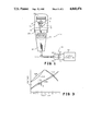
- FIG. 3 is a diagram illustrating ideal and actual voltages at various points in the circuit of FIG. 2.
- FIG. 1 is a semi-schematic representation of a scanning mechanical ultrasonic transducer system utilizing the teachings of this invention.
- the transducer system includes a transducer head 1O, a cable 12 leading from head 10 to the plug 14 of a connector 16 and system circuitry 18 connected to the socket 22 of connector 16.
- Head 10 has a main body or casing 24 to the top of which is secured a transparent cover 26.
- cover 26 is shown secured to body 24 by screw joint 28.
- the sealed cavity 30 formed within cover 26 is normally filled with an acoustic coupling fluid having an acoustic impedance substantially matching that of the object being imaged.
- transducer element 32 which is adapted to alternately generate and receive ultrasonic acoustic signals.
- Element 32 is attached to a base 34 which is mounted in the cavity to be pivoted about shaft 36.
- a flexible member such as a spring, wire or cord 38 wraps at one end around a pulley 40 attached to base 34 and is attached to the pulley.
- the other end of member 38 is attached to servo-motor 42 which is mounted in casing 24. Movement of motor 42 is transmitted through member 38 to rotate base 34 and transducer element 32 mounted thereto in one direction, and to control the return of these elements in the opposite direction.
- a vane or fin 44 is attached to the underside of base 34, the vane being wider on one side than on the other and varying in width (radius) between the two ends in a predetermined manner (such as, for example, a section of a spiral). Vane 44 travels through a slot in a toroidal inductor 46 causing predetermined variations in the inductance thereof which varies as a function of the angular position of transducer element 32. Ideally, the inductance of inductor 46 varies linearly with the angular position of the transducer element. However, as has been previously discussed, this objective is not easily achievable and the output from the toroidal inductor is therefore generally, at least to some degree, nonlinear.
- a memory device 50 Positioned in connector plug 14 is a memory device 50. This may be a programmable read-only memory (PROM) but is preferably an erasable PROM (EPROM). For a preferred embodiment, memory device 50 is an electrically erasable PROM (EEPROM). An EEPROM may be digitally addressed and accessed in the same manner as a random access memory and may have information erased and rewritten in any and all of its memory locations. Memory 50 is electrically connected by for example pins 52 to system circuitry 18.
- PROM programmable read-only memory
- EPROM erasable PROM
- EEPROM electrically erasable PROM
- An EEPROM may be digitally addressed and accessed in the same manner as a random access memory and may have information erased and rewritten in any and all of its memory locations.
- Memory 50 is electrically connected by for example pins 52 to system circuitry 18.
- FIG. 2 is a general schematic diagram of the system of this invention. Included as part of system circuitry 18 is a processor 60 which may, for simpler applications, be a standard microprocessor. For more complex applications, the processor 60 may be a minicomputer. Processor 60 receives certain information which will be described in greater detail hereinafter from memory device 50 and utilizes such information in conjunction with other information applied thereto to control, among other things, the scanning of and output power from transducer element 32. In particular, processor 60 generates the reference signal to be used for control of servo-motor 42 and stores a digital representation of such signal in reference signal store 62. This information is periodically read out and applied through digital to analog converter 64 as one input to comparator 66. The other input to comparator 66 is the output from position sensor 68.
- processor 60 receives certain information which will be described in greater detail hereinafter from memory device 50 and utilizes such information in conjunction with other information applied thereto to control, among other things, the scanning of and output power from transducer element 32.
- processor 60 generates the
- Position sensor 68 includes inductor 46 and vane 44, the output being from inductor 46.
- the output from comparator 66 which ay, for example, be part of system circuitry 18, is a voltage which is proportional to the difference between the actual position of transducer element 32 and the desired rotational position of this element. This signal is applied to control servo-motor 42.
- the elements 62-68 and 42 operate in a standard manner to cause transducer element 32 to be rocked back and forth about pivot 36 at a frequency and otherwise in accordance with the reference signal stored in reference signal store 62.
- processor 60 generates and stores in position store 69 a table of voltage values from position sensor 68 which correspond to transducer positions in its scan path at which readings or other desired actions are to be taken. This information is periodically read out and applied through D/A converter 71 as one input to comparator 73. The other input to comparator 73 is the output from position sensor 68. The output from comparator 73 is applied to trigger transducer element 32. Except as hereinafter discussed, the nature and operation of this triggering circuit is also conventional.
- Processor 60 also determines the power level output from transducer 32 and stores a digital indication of the desired power level in power level store 70.
- the output from power level store 70 is applied through digital to analog convertor 72 to control the power level output from transducer element 32.
- Memory 50 may have a number of different storage areas. While separate lines have been shown leading from each storage area to processor 60, it should be understood that the memory 50 may be addressed from the processor and the output from all areas thereof applied through a common output bus.
- memory 50 is shown as having an area 80 which stores information concerning nonlinearity errors in position sensor 68, an area 82 which stores power tables used for controlling the power output of transducer 32, and an area 84 for storing general information concerning the transducer such as its type, model number, serial number, advertised and actual measured operating frequencies, advertised and actual focal distance and the like.
- Area 82 may contain a field-of-use or class-of-use control byte 83 which may be used to inhibit the transducer from being used for selected uses for which it is not suitable.
- Area 84 may also store certain constants used in connection with operating the transducer and interpreting the results thereof. While the areas 80-84 of memory 50 may be stored in an EEPROM, it is contemplated that the information in these areas of memory would be read only.
- memory 50 has an area 86 which stores various information concerning the duration of use of the transducer, such as total hours of actual use, hours of use since last maintenance, hours of use for various classes of service, or the like. Entries in this area of memory would be periodically erased and rewritten as the transducer is used. Various other information may also be recorded in this area of memory.
- the output from position sensor 68 varies as a direct linear function of the angular position of transducer element 32.
- the actual output from the position sensor may in fact vary nonlinearly as shown for example by the line 102. It should be emphasized that the line 102 is shown for purposes of illustration only and the nonlinearity may take any form.
- the nonlinearity may all be in one direction, the actual curve may follow the ideal curve for some portion of the scan path, and there may be one or more crossovers which occur at any point along the scan path.
- the nonlinearity in the position indication from sensor 68 may cause one or more of these readings to be taken at the wrong point in the scan path and may result in uneven spacing between successive readings.
- processor 60 would cause the reading at point C in the scan path to occur when the voltage level from position sensor 68 is at level X.
- the actual output from position sensor 68 at selected points in the scan path is measured and the actual or incremental deviation of this value from the desired value, represented by the line 100, at that point in the scan path is stored in area 80 of memory 50.
- processor 60 initially stores a table with the voltage values from position sensor 68 at which each reading or other desired action is to be taken in position table store 69.
- processor 60 When plug 14 is mated with socket 22, processor 60 reads the contents of area 80 of the memory 50 for the transducer and utilizes the deviation value stored for each point in the scan path at which a reading is to be taken to modify the voltage value in the table in store 69 for that point so that readings in fact occur at precisely the right positions in the scan path for the transducer being utilized.
- the deviation (d) would be added to the value X stored in the table so that for this transducer, the reading at position C would occur when the output from position sensor 68 was equal to a voltage of (X+d).
- the system is thus able to use position sensors with lower tolerances while still achieving a very high level of linearity in the operation of the system.
- the output of position sensor 68 is also utilized to control the movement of servo-motor 42.
- the nonlinearity in the output of position sensor 68 can also cause nonlinearities in the movement of the servo-motor resulting in the scan rate of transducer element 32 being non-uniform and in uneven spacing between the points, such as the points A-I, where readings or other action is taken.
- the above problem is dealt with by modifying the reference signal stored in store 62 in a manner equal and opposite from that of the nonlinearity in the position signal from sensor 68.
- the reference signal for the sweep in one direction may, for example, have the shape of curve 104 in FIG. 3.
- processor 60 utilizes the deviation information in area 80 of memory 50 to modify the reference signal stored in store 62 to, for example, the reference signal 106 shown in FIG. 3 so that the inputs to comparator 66 result in uniform drive signals to servo-motor 42.
- the output audio power from transducer element 32 will vary slightly from transducer element to transducer element for a given potential input to the transducer from converter 72. Since the output power from the transducer for various classes of service is tightly controlled by the FDA, and in order to avoid potential harm to a patient, it is important that the actual output power correspond very closely to the desired output power. Transducers in the past have frequently operated below optimum power to avoid any possibility of excessive output from a given transducer element.
- the actual power output from the transducer element 32 used in a given transducer is measured for selected inputs at a final stage in the manufacture or testing of the transducer and this information is stored as a power table in area 82 of memory 50 for the transducer.
- processor 60 reads the information from the power table for the transducer into its own memory and utilizes that information to store the appropriate power level value in store 70 for a desired power level output from transducer 32.
- byte 83 in area 82 may be appropriately set. This byte is detected by processor 60 and utilized by the processor to inhibit the use of the transducer for the prohibited classes of service. For example, if the transducer is not suitable for use for fetal scanning, the byte 83 would indicate that this class of service was prohibited and would be stored in an appropriate location in processor 60. If the processor was advised that the system was to be used for fetal scanning, it would check the contents of this byte in its memory and if the byte indicated that such scanning was not permitted for the transducer, the processor would inhibit the use of the system for such scanning, until the transducer was replaced.
- processor 60 At the same time that the information in areas 80 and 82 of memory 50 are read into the memory of processor 60, the various items of general information and constants stored in area 84 of the memory would also be read into processor 60. These values would be used by the processor as appropriate in operating the system or in interpreting the results thereof. They might also be used for service or other purposes. The values stored and used are in each instance the correct values for the particular transducer being utilized. Further, this information is available to the system for new classes of transducers or even an experimental transducer which is to be used with the system without requiring that the system be reprogrammed as each new class of transducer comes on the market. It is therefore much quicker and easier to introduce new types of transducers.
- area 86 of the memory is adapted to store selected information concerning the operation of the transducer.
- the information which is initially stored in this area of memory 50 which may initially be completely blank, is read into an appropriate area in the memory of processor 60.
- This information is then updated by the processor to reflect operation of the transducer and is periodically written into the appropriate position in area 86.
- processor 60 may maintain a running tally of the duration of use of the transducer and may read the current setting of this tally into the appropriate location in area 86 at the end of each session, or at other selected times.
- memory 50 has been shown located in plug 14 of connector 16, it is apparent that the memory device 50 could be located at any appropriate location in the transducer assembly consisting of head 10, cable 12 and plug 14. Factors in selecting the location are available space, ability to make connections and length of connection. Thus, while the memory device must be mounted integrally with transducer element 32, the precise location in the transducer assembly where it is located is not critical.
- memory 50 has been shown as having areas 80-86 for the preferred embodiment, the memory 50 used for a particular application might have any one or more of these areas or might have one or more areas storing different information as required for the application.
- the teachings of this invention could be utilized to compensate for any measurable error which might arise in the mechanism for controlling the movement or scan position of the transducer, including, but by no means limited to a nonlinearity in the sensor itself, or the like.
- the teachings of this invention could also be utilized to compensate for variations among transducer elements in some other characteristic or aspect of the transducer output such as, for example, frequency.
Abstract
Description
Claims (22)
Priority Applications (4)
| Application Number | Priority Date | Filing Date | Title |
|---|---|---|---|
| US07/115,689 US4868476A (en) | 1987-10-30 | 1987-10-30 | Transducer with integral memory |
| JP63274340A JPH0880301A (en) | 1987-10-30 | 1988-10-28 | Converter system |
| DE88310197T DE3886170T2 (en) | 1987-10-30 | 1988-10-31 | Converter. |
| EP88310197A EP0314514B1 (en) | 1987-10-30 | 1988-10-31 | Transducer |
Applications Claiming Priority (1)
| Application Number | Priority Date | Filing Date | Title |
|---|---|---|---|
| US07/115,689 US4868476A (en) | 1987-10-30 | 1987-10-30 | Transducer with integral memory |
Publications (1)
| Publication Number | Publication Date |
|---|---|
| US4868476A true US4868476A (en) | 1989-09-19 |
Family
ID=22362871
Family Applications (1)
| Application Number | Title | Priority Date | Filing Date |
|---|---|---|---|
| US07/115,689 Expired - Lifetime US4868476A (en) | 1987-10-30 | 1987-10-30 | Transducer with integral memory |
Country Status (4)
| Country | Link |
|---|---|
| US (1) | US4868476A (en) |
| EP (1) | EP0314514B1 (en) |
| JP (1) | JPH0880301A (en) |
| DE (1) | DE3886170T2 (en) |
Cited By (51)
| Publication number | Priority date | Publication date | Assignee | Title |
|---|---|---|---|---|
| US5089979A (en) * | 1989-02-08 | 1992-02-18 | Basic Measuring Instruments | Apparatus for digital calibration of detachable transducers |
| US5309075A (en) * | 1990-03-23 | 1994-05-03 | Toyoda Koki Kabushiki Kaisha | Digital servo-control apparatus for preventing torque variations |
| US5374883A (en) * | 1992-09-02 | 1994-12-20 | Cincinnati Milacron Inc. | Method and apparatus for position error compensation |
| US5425375A (en) * | 1993-09-09 | 1995-06-20 | Cardiac Pathways Corporation | Reusable medical device with usage memory, system using same |
| US5429129A (en) * | 1991-08-22 | 1995-07-04 | Sensor Devices, Inc. | Apparatus for determining spectral absorption by a specific substance in a fluid |
| DE19531360A1 (en) * | 1994-10-31 | 1996-05-02 | Hewlett Packard Co | Transducer sensitivity control device for ultrasonic imaging system |
| US5521846A (en) * | 1991-10-30 | 1996-05-28 | Labinal, Societe Anonyme | Device for measuring parameters, in particular parameters relating to aircraft or vehicle wheels |
| US5528519A (en) * | 1993-05-20 | 1996-06-18 | Otax Co., Ltd. | Connector for measuring apparatus |
| US5588438A (en) * | 1991-01-29 | 1996-12-31 | Interflo Medical, Inc. | System and method for controlling the temperature of a catheter-mounted heater |
| US5657761A (en) * | 1994-04-22 | 1997-08-19 | Hitachi Medical Corporation | Ultrasonic diagnosis system |
| US5720293A (en) * | 1991-01-29 | 1998-02-24 | Baxter International Inc. | Diagnostic catheter with memory |
| US5807269A (en) * | 1991-01-29 | 1998-09-15 | Baxter International Inc. | Thermodilution catheter having a safe, flexible heating element |
| US5808902A (en) * | 1996-05-23 | 1998-09-15 | Basic Measuring Instruments | Power quality transducer for use with supervisory control systems |
| US6032109A (en) * | 1996-10-21 | 2000-02-29 | Telemonitor, Inc. | Smart sensor module |
| US6232764B1 (en) | 1998-06-12 | 2001-05-15 | Tektronix, Inc. | Accessory with internal adjustments controlled by host |
| US6243654B1 (en) | 1997-10-07 | 2001-06-05 | Telemonitor, Inc. | Transducer assembly with smart connector |
| US6270460B1 (en) | 1999-06-24 | 2001-08-07 | Acuson Corporation | Apparatus and method to limit the life span of a diagnostic medical ultrasound probe |
| US6298255B1 (en) | 1999-06-09 | 2001-10-02 | Aspect Medical Systems, Inc. | Smart electrophysiological sensor system with automatic authentication and validation and an interface for a smart electrophysiological sensor system |
| US6321171B1 (en) | 1998-04-03 | 2001-11-20 | Tektronix, Inc. | Electronic measurement instrument probe accessory offset, gain, and linearity correction method |
| US6423002B1 (en) * | 1999-06-24 | 2002-07-23 | Acuson Corporation | Intra-operative diagnostic ultrasound multiple-array transducer probe and optional surgical tool |
| US20020193709A1 (en) * | 2001-05-23 | 2002-12-19 | Rudiger Bolze | Apparatus for administering acoustic shock waves having a removable and replaceable component a data storage medium |
| US6656119B2 (en) * | 2000-03-17 | 2003-12-02 | Kabushiki Kaisha Toshiba | Imaging diagnostic apparatus and maintenance method of the same |
| US20050049501A1 (en) * | 1999-09-03 | 2005-03-03 | Conero Ronald S. | Smart physiologic parameter sensor and method |
| US20050159802A1 (en) * | 2004-01-15 | 2005-07-21 | Icon Interventional Systems, Inc., An Ohio Corporation | Method for verifying position on an angioplasty balloon |
| US20050228617A1 (en) * | 2004-04-02 | 2005-10-13 | Scott Kerwin | Methods and systems for tracking probe use |
| US20060058674A1 (en) * | 2004-08-31 | 2006-03-16 | General Electric Company | Optimizing ultrasound acquisition based on ultrasound-located landmarks |
| US20060217605A1 (en) * | 2000-08-31 | 2006-09-28 | Nellcor Puritan Bennett Inc. | Oximeter sensor with digital memory encoding sensor data |
| US20060241424A1 (en) * | 2003-03-20 | 2006-10-26 | Matsushita Electric Industrial Co., Ltd. | Ultrasonic probe and ultrasonographic device |
| US20060290488A1 (en) * | 2005-05-27 | 2006-12-28 | Bionime Corporation | Coding module and sensing meter and system therefor |
| US20070083111A1 (en) * | 2005-10-12 | 2007-04-12 | Volcano Corporation | Apparatus and method for use of RFID catheter intelligence |
| US7273483B2 (en) * | 2000-10-20 | 2007-09-25 | Ethicon Endo-Surgery, Inc. | Apparatus and method for alerting generator functions in an ultrasonic surgical system |
| US20070265715A1 (en) * | 2004-04-26 | 2007-11-15 | Benoit Chouinard | Method for Permanent Calibration Based on Actual Measurement |
| US20090216121A1 (en) * | 2005-06-03 | 2009-08-27 | Theraclion | Head for imaging and treating organs of living beings and method for making same |
| US20090299180A1 (en) * | 2005-06-03 | 2009-12-03 | Theraclion | Distance-determining method and treatment apparatus which uses said method |
| US7946994B2 (en) | 2004-10-07 | 2011-05-24 | Tensys Medical, Inc. | Compact apparatus and methods for non-invasively measuring hemodynamic parameters |
| US8151127B2 (en) | 2000-07-26 | 2012-04-03 | Bridgestone Americas Tire Operations, Llc | System for conserving battery life in a battery operated device |
| US8266465B2 (en) | 2000-07-26 | 2012-09-11 | Bridgestone Americas Tire Operation, LLC | System for conserving battery life in a battery operated device |
| US8568322B2 (en) | 2005-06-03 | 2013-10-29 | Theraclion | Head for imaging and treating organs of living organisms and production method thereof |
| US9131882B2 (en) | 2005-03-01 | 2015-09-15 | Cercacor Laboratories, Inc. | Noninvasive multi-parameter patient monitor |
| US9138180B1 (en) | 2010-05-03 | 2015-09-22 | Masimo Corporation | Sensor adapter cable |
| US9301730B2 (en) | 2005-04-18 | 2016-04-05 | Koninklijke Philips N.V. | Ultrasonic diagnostic imaging system configured by probe firmware |
| WO2016198989A1 (en) | 2015-06-11 | 2016-12-15 | Koninklijke Philips N.V. | Ultrasonic transducer array probe for shear wave imaging |
| WO2017049078A1 (en) * | 2015-09-18 | 2017-03-23 | Chirp Microsystems, Inc. | Programmable ultrasonic transceiver |
| US9702969B2 (en) | 2009-05-13 | 2017-07-11 | Koninklijke Philips Electronics N.V. | Ultrasonic blood flow doppler audio with pitch shifting |
| US9848807B2 (en) | 2007-04-21 | 2017-12-26 | Masimo Corporation | Tissue profile wellness monitor |
| US9949676B2 (en) | 2006-10-12 | 2018-04-24 | Masimo Corporation | Patient monitor capable of monitoring the quality of attached probes and accessories |
| US10285598B2 (en) | 2006-05-13 | 2019-05-14 | United States Gtm Medical Devices | Continuous positioning apparatus and methods |
| US10335081B2 (en) | 2002-01-30 | 2019-07-02 | United States Gtm Medical Devices | Apparatus and method for interfacing time-variant signals |
| US10729402B2 (en) | 2009-12-04 | 2020-08-04 | Masimo Corporation | Calibration for multi-stage physiological monitors |
| US10952675B2 (en) | 2007-10-12 | 2021-03-23 | Shangyi Medical Technology (Hangzhou) Co., Ltd | Apparatus and methods for non-invasively measuring a patient's arterial blood pressure |
| US11534087B2 (en) | 2009-11-24 | 2022-12-27 | Cercacor Laboratories, Inc. | Physiological measurement system with automatic wavelength adjustment |
Families Citing this family (1)
| Publication number | Priority date | Publication date | Assignee | Title |
|---|---|---|---|---|
| US5291392A (en) * | 1992-02-19 | 1994-03-01 | Gerber Systems Corporation | Method and apparatus for enhancing the accuracy of scanner systems |
Citations (12)
| Publication number | Priority date | Publication date | Assignee | Title |
|---|---|---|---|---|
| US3854281A (en) * | 1973-01-31 | 1974-12-17 | Eaton Corp | Hourmeter for equipment having short operating times |
| US4149419A (en) * | 1977-11-25 | 1979-04-17 | Smith Kline Instruments, Inc. | Ultrasonic transducer probe |
| DE3116690A1 (en) * | 1981-04-28 | 1982-11-11 | Rohde & Schwarz GmbH & Co KG, 8000 München | MEASURING PROBE |
| US4399703A (en) * | 1980-10-16 | 1983-08-23 | Dymax Corporation | Ultrasonic transducer and integral drive circuit therefor |
| US4446715A (en) * | 1982-06-07 | 1984-05-08 | Camino Laboratories, Inc. | Transducer calibration system |
| US4479388A (en) * | 1982-09-20 | 1984-10-30 | Dymax Corporation | Ultrasound transducer and drive system |
| US4517985A (en) * | 1982-06-01 | 1985-05-21 | Diasonics, Inc. | Neonate ultrasonic scanner |
| US4530362A (en) * | 1982-07-19 | 1985-07-23 | Siemens Aktiengesellschaft | Ultrasound device for sector scanning |
| US4628499A (en) * | 1984-06-01 | 1986-12-09 | Scientific-Atlanta, Inc. | Linear servoactuator with integrated transformer position sensor |
| US4664123A (en) * | 1984-06-26 | 1987-05-12 | Kabushiki Kaisha Toshiba | Ultrasonic method and apparatus for tissue characterization and imaging nonlinear parameter |
| US4674515A (en) * | 1984-10-26 | 1987-06-23 | Olympus Optical Co., Ltd. | Ultrasonic endoscope |
| US4688576A (en) * | 1985-01-14 | 1987-08-25 | Technicare Corporation | Ultrasonic transducer probe assembly |
Family Cites Families (7)
| Publication number | Priority date | Publication date | Assignee | Title |
|---|---|---|---|---|
| JPS5711634A (en) * | 1980-06-26 | 1982-01-21 | Tokyo Shibaura Electric Co | Apparatus for measuring live body information |
| JPH0663779B2 (en) * | 1981-11-10 | 1994-08-22 | セントロン ベー.オー.エフ. | Biological parameter detection system |
| JPS6014110A (en) * | 1983-07-06 | 1985-01-24 | Fanuc Ltd | Detection for absolute position of servo control system |
| JPS6060507A (en) * | 1983-09-14 | 1985-04-08 | Mitsubishi Electric Corp | Device for correcting error of position detector |
| US4587971A (en) * | 1984-11-29 | 1986-05-13 | North American Philips Corporation | Ultrasonic scanning apparatus |
| JPS61176326A (en) * | 1985-02-01 | 1986-08-08 | 株式会社日立製作所 | Diagnostic apparatus |
| JPS61232838A (en) * | 1985-04-09 | 1986-10-17 | カヤバ工業株式会社 | Mechanical drive type blood stream measuring method and apparatus |
-
1987
- 1987-10-30 US US07/115,689 patent/US4868476A/en not_active Expired - Lifetime
-
1988
- 1988-10-28 JP JP63274340A patent/JPH0880301A/en active Pending
- 1988-10-31 EP EP88310197A patent/EP0314514B1/en not_active Expired - Lifetime
- 1988-10-31 DE DE88310197T patent/DE3886170T2/en not_active Expired - Fee Related
Patent Citations (13)
| Publication number | Priority date | Publication date | Assignee | Title |
|---|---|---|---|---|
| US3854281A (en) * | 1973-01-31 | 1974-12-17 | Eaton Corp | Hourmeter for equipment having short operating times |
| US4149419A (en) * | 1977-11-25 | 1979-04-17 | Smith Kline Instruments, Inc. | Ultrasonic transducer probe |
| US4399703A (en) * | 1980-10-16 | 1983-08-23 | Dymax Corporation | Ultrasonic transducer and integral drive circuit therefor |
| DE3116690A1 (en) * | 1981-04-28 | 1982-11-11 | Rohde & Schwarz GmbH & Co KG, 8000 München | MEASURING PROBE |
| US4517985A (en) * | 1982-06-01 | 1985-05-21 | Diasonics, Inc. | Neonate ultrasonic scanner |
| US4446715A (en) * | 1982-06-07 | 1984-05-08 | Camino Laboratories, Inc. | Transducer calibration system |
| US4446715B1 (en) * | 1982-06-07 | 1991-09-17 | Camino Lab Inc | |
| US4530362A (en) * | 1982-07-19 | 1985-07-23 | Siemens Aktiengesellschaft | Ultrasound device for sector scanning |
| US4479388A (en) * | 1982-09-20 | 1984-10-30 | Dymax Corporation | Ultrasound transducer and drive system |
| US4628499A (en) * | 1984-06-01 | 1986-12-09 | Scientific-Atlanta, Inc. | Linear servoactuator with integrated transformer position sensor |
| US4664123A (en) * | 1984-06-26 | 1987-05-12 | Kabushiki Kaisha Toshiba | Ultrasonic method and apparatus for tissue characterization and imaging nonlinear parameter |
| US4674515A (en) * | 1984-10-26 | 1987-06-23 | Olympus Optical Co., Ltd. | Ultrasonic endoscope |
| US4688576A (en) * | 1985-01-14 | 1987-08-25 | Technicare Corporation | Ultrasonic transducer probe assembly |
Non-Patent Citations (2)
| Title |
|---|
| John Krieger, "Memory for Transducer System", Electronic Engineering Times, Jun. 13, 1977, pp. 33-34. |
| John Krieger, Memory for Transducer System , Electronic Engineering Times, Jun. 13, 1977, pp. 33 34. * |
Cited By (93)
| Publication number | Priority date | Publication date | Assignee | Title |
|---|---|---|---|---|
| US5089979A (en) * | 1989-02-08 | 1992-02-18 | Basic Measuring Instruments | Apparatus for digital calibration of detachable transducers |
| US5309075A (en) * | 1990-03-23 | 1994-05-03 | Toyoda Koki Kabushiki Kaisha | Digital servo-control apparatus for preventing torque variations |
| US6355001B1 (en) | 1991-01-29 | 2002-03-12 | Edwards Lifesciences Corporation | Thermodilution catheter method using a safe, flexible heating element |
| US5807269A (en) * | 1991-01-29 | 1998-09-15 | Baxter International Inc. | Thermodilution catheter having a safe, flexible heating element |
| US5720293A (en) * | 1991-01-29 | 1998-02-24 | Baxter International Inc. | Diagnostic catheter with memory |
| US6387052B1 (en) | 1991-01-29 | 2002-05-14 | Edwards Lifesciences Corporation | Thermodilution catheter having a safe, flexible heating element |
| US5857976A (en) * | 1991-01-29 | 1999-01-12 | Baxter International Inc. | Thermodilution catheter having a safe, flexible heating element |
| US7254946B1 (en) | 1991-01-29 | 2007-08-14 | Edwards Lifesciences Corporation | Thermodilution catheter having a safe, flexible heating element |
| US5588438A (en) * | 1991-01-29 | 1996-12-31 | Interflo Medical, Inc. | System and method for controlling the temperature of a catheter-mounted heater |
| US5429129A (en) * | 1991-08-22 | 1995-07-04 | Sensor Devices, Inc. | Apparatus for determining spectral absorption by a specific substance in a fluid |
| US5521846A (en) * | 1991-10-30 | 1996-05-28 | Labinal, Societe Anonyme | Device for measuring parameters, in particular parameters relating to aircraft or vehicle wheels |
| US5374883A (en) * | 1992-09-02 | 1994-12-20 | Cincinnati Milacron Inc. | Method and apparatus for position error compensation |
| US5528519A (en) * | 1993-05-20 | 1996-06-18 | Otax Co., Ltd. | Connector for measuring apparatus |
| US5425375A (en) * | 1993-09-09 | 1995-06-20 | Cardiac Pathways Corporation | Reusable medical device with usage memory, system using same |
| US5657761A (en) * | 1994-04-22 | 1997-08-19 | Hitachi Medical Corporation | Ultrasonic diagnosis system |
| US5889194A (en) * | 1994-10-31 | 1999-03-30 | Hewlett-Packard Company | Apparatus for controlling the sensitivity of transducer elements of an array |
| US5684243A (en) * | 1994-10-31 | 1997-11-04 | Hewlett-Packard Company | Methods for controlling sensitivity of electrostrictive transducers |
| US5585546A (en) * | 1994-10-31 | 1996-12-17 | Hewlett-Packard Company | Apparatus and methods for controlling sensitivity of transducers |
| DE19531360B4 (en) * | 1994-10-31 | 2004-11-04 | Agilent Technologies, Inc. (n.d.Ges.d.Staates Delaware), Palo Alto | Device and method for controlling the sensitivity of transducers |
| DE19531360A1 (en) * | 1994-10-31 | 1996-05-02 | Hewlett Packard Co | Transducer sensitivity control device for ultrasonic imaging system |
| US5808902A (en) * | 1996-05-23 | 1998-09-15 | Basic Measuring Instruments | Power quality transducer for use with supervisory control systems |
| US6032109A (en) * | 1996-10-21 | 2000-02-29 | Telemonitor, Inc. | Smart sensor module |
| US6243654B1 (en) | 1997-10-07 | 2001-06-05 | Telemonitor, Inc. | Transducer assembly with smart connector |
| US6321171B1 (en) | 1998-04-03 | 2001-11-20 | Tektronix, Inc. | Electronic measurement instrument probe accessory offset, gain, and linearity correction method |
| US6232764B1 (en) | 1998-06-12 | 2001-05-15 | Tektronix, Inc. | Accessory with internal adjustments controlled by host |
| US6298255B1 (en) | 1999-06-09 | 2001-10-02 | Aspect Medical Systems, Inc. | Smart electrophysiological sensor system with automatic authentication and validation and an interface for a smart electrophysiological sensor system |
| US6423002B1 (en) * | 1999-06-24 | 2002-07-23 | Acuson Corporation | Intra-operative diagnostic ultrasound multiple-array transducer probe and optional surgical tool |
| US6270460B1 (en) | 1999-06-24 | 2001-08-07 | Acuson Corporation | Apparatus and method to limit the life span of a diagnostic medical ultrasound probe |
| US20050049501A1 (en) * | 1999-09-03 | 2005-03-03 | Conero Ronald S. | Smart physiologic parameter sensor and method |
| US6656119B2 (en) * | 2000-03-17 | 2003-12-02 | Kabushiki Kaisha Toshiba | Imaging diagnostic apparatus and maintenance method of the same |
| US8151127B2 (en) | 2000-07-26 | 2012-04-03 | Bridgestone Americas Tire Operations, Llc | System for conserving battery life in a battery operated device |
| US8266465B2 (en) | 2000-07-26 | 2012-09-11 | Bridgestone Americas Tire Operation, LLC | System for conserving battery life in a battery operated device |
| US20060217605A1 (en) * | 2000-08-31 | 2006-09-28 | Nellcor Puritan Bennett Inc. | Oximeter sensor with digital memory encoding sensor data |
| US8639307B2 (en) | 2000-08-31 | 2014-01-28 | Covidien Lp | Oximeter sensor with digital memory encoding sensor data |
| US20090118751A1 (en) * | 2000-10-20 | 2009-05-07 | Wiener Eitan T | Apparatus and method for alerting generator functions in an ultrasonic surgical system |
| US7273483B2 (en) * | 2000-10-20 | 2007-09-25 | Ethicon Endo-Surgery, Inc. | Apparatus and method for alerting generator functions in an ultrasonic surgical system |
| US7364554B2 (en) * | 2001-05-23 | 2008-04-29 | Sanuwave, Inc. | Apparatus for administering acoustic shock waves having a removable and replaceable component with a data storage medium |
| US20020193709A1 (en) * | 2001-05-23 | 2002-12-19 | Rudiger Bolze | Apparatus for administering acoustic shock waves having a removable and replaceable component a data storage medium |
| US10335081B2 (en) | 2002-01-30 | 2019-07-02 | United States Gtm Medical Devices | Apparatus and method for interfacing time-variant signals |
| US20060241424A1 (en) * | 2003-03-20 | 2006-10-26 | Matsushita Electric Industrial Co., Ltd. | Ultrasonic probe and ultrasonographic device |
| US20110196618A1 (en) * | 2004-01-15 | 2011-08-11 | Icon Interventional Systems, Inc. | Method for verifying position on an angioplasty balloon |
| US7945409B2 (en) * | 2004-01-15 | 2011-05-17 | Icon Interventional Systems, Inc. | Method for verifying position on an angioplasty balloon |
| US20050159802A1 (en) * | 2004-01-15 | 2005-07-21 | Icon Interventional Systems, Inc., An Ohio Corporation | Method for verifying position on an angioplasty balloon |
| US20050228617A1 (en) * | 2004-04-02 | 2005-10-13 | Scott Kerwin | Methods and systems for tracking probe use |
| US20070265715A1 (en) * | 2004-04-26 | 2007-11-15 | Benoit Chouinard | Method for Permanent Calibration Based on Actual Measurement |
| US7634374B2 (en) * | 2004-04-26 | 2009-12-15 | Orthosoft Inc. | Method for permanent calibration based on actual measurement |
| US20060058674A1 (en) * | 2004-08-31 | 2006-03-16 | General Electric Company | Optimizing ultrasound acquisition based on ultrasound-located landmarks |
| US7946994B2 (en) | 2004-10-07 | 2011-05-24 | Tensys Medical, Inc. | Compact apparatus and methods for non-invasively measuring hemodynamic parameters |
| US9247886B2 (en) | 2004-10-07 | 2016-02-02 | Tensys Medical, Inc. | Compact apparatus and methods for non-invasively measuring hemodynamic parameters |
| US9131882B2 (en) | 2005-03-01 | 2015-09-15 | Cercacor Laboratories, Inc. | Noninvasive multi-parameter patient monitor |
| US9351675B2 (en) | 2005-03-01 | 2016-05-31 | Cercacor Laboratories, Inc. | Noninvasive multi-parameter patient monitor |
| US10856788B2 (en) | 2005-03-01 | 2020-12-08 | Cercacor Laboratories, Inc. | Noninvasive multi-parameter patient monitor |
| US9241662B2 (en) | 2005-03-01 | 2016-01-26 | Cercacor Laboratories, Inc. | Configurable physiological measurement system |
| US10251585B2 (en) | 2005-03-01 | 2019-04-09 | Cercacor Laboratories, Inc. | Noninvasive multi-parameter patient monitor |
| US11430572B2 (en) | 2005-03-01 | 2022-08-30 | Cercacor Laboratories, Inc. | Multiple wavelength sensor emitters |
| US10984911B2 (en) | 2005-03-01 | 2021-04-20 | Cercacor Laboratories, Inc. | Multiple wavelength sensor emitters |
| US9750443B2 (en) | 2005-03-01 | 2017-09-05 | Cercacor Laboratories, Inc. | Multiple wavelength sensor emitters |
| US10123726B2 (en) | 2005-03-01 | 2018-11-13 | Cercacor Laboratories, Inc. | Configurable physiological measurement system |
| US9549696B2 (en) | 2005-03-01 | 2017-01-24 | Cercacor Laboratories, Inc. | Physiological parameter confidence measure |
| US10327683B2 (en) | 2005-03-01 | 2019-06-25 | Cercacor Laboratories, Inc. | Multiple wavelength sensor emitters |
| US11545263B2 (en) | 2005-03-01 | 2023-01-03 | Cercacor Laboratories, Inc. | Multiple wavelength sensor emitters |
| US9301730B2 (en) | 2005-04-18 | 2016-04-05 | Koninklijke Philips N.V. | Ultrasonic diagnostic imaging system configured by probe firmware |
| US20060290488A1 (en) * | 2005-05-27 | 2006-12-28 | Bionime Corporation | Coding module and sensing meter and system therefor |
| US20090299180A1 (en) * | 2005-06-03 | 2009-12-03 | Theraclion | Distance-determining method and treatment apparatus which uses said method |
| US8517943B2 (en) * | 2005-06-03 | 2013-08-27 | Theraclion | Head for imaging and treating organs of living beings and method for making same |
| US20090216121A1 (en) * | 2005-06-03 | 2009-08-27 | Theraclion | Head for imaging and treating organs of living beings and method for making same |
| US8568322B2 (en) | 2005-06-03 | 2013-10-29 | Theraclion | Head for imaging and treating organs of living organisms and production method thereof |
| US10052082B2 (en) * | 2005-10-12 | 2018-08-21 | Volcano Corporation | Apparatus and method for use of RFID catheter intelligence |
| US9101298B2 (en) * | 2005-10-12 | 2015-08-11 | Volcano Corporation | Apparatus and method for use of RFID catheter intelligence |
| US7988633B2 (en) * | 2005-10-12 | 2011-08-02 | Volcano Corporation | Apparatus and method for use of RFID catheter intelligence |
| US20110270091A1 (en) * | 2005-10-12 | 2011-11-03 | Volcano Corporation | Apparatus and Method for Use of RFID Catheter Intelligence |
| US20070083111A1 (en) * | 2005-10-12 | 2007-04-12 | Volcano Corporation | Apparatus and method for use of RFID catheter intelligence |
| US20150342564A1 (en) * | 2005-10-12 | 2015-12-03 | Volcano Corporation | Apparatus and method for use of rfid catheter intelligence |
| US10285598B2 (en) | 2006-05-13 | 2019-05-14 | United States Gtm Medical Devices | Continuous positioning apparatus and methods |
| US9949676B2 (en) | 2006-10-12 | 2018-04-24 | Masimo Corporation | Patient monitor capable of monitoring the quality of attached probes and accessories |
| US11857315B2 (en) | 2006-10-12 | 2024-01-02 | Masimo Corporation | Patient monitor capable of monitoring the quality of attached probes and accessories |
| US10993643B2 (en) | 2006-10-12 | 2021-05-04 | Masimo Corporation | Patient monitor capable of monitoring the quality of attached probes and accessories |
| US10251586B2 (en) | 2007-04-21 | 2019-04-09 | Masimo Corporation | Tissue profile wellness monitor |
| US9848807B2 (en) | 2007-04-21 | 2017-12-26 | Masimo Corporation | Tissue profile wellness monitor |
| US10980457B2 (en) | 2007-04-21 | 2021-04-20 | Masimo Corporation | Tissue profile wellness monitor |
| US11647923B2 (en) | 2007-04-21 | 2023-05-16 | Masimo Corporation | Tissue profile wellness monitor |
| US10952675B2 (en) | 2007-10-12 | 2021-03-23 | Shangyi Medical Technology (Hangzhou) Co., Ltd | Apparatus and methods for non-invasively measuring a patient's arterial blood pressure |
| US10732269B2 (en) | 2009-05-13 | 2020-08-04 | Koninklijke Philips N.V. | Ultrasound blood flow Doppler audio with pitch shifting |
| US9702969B2 (en) | 2009-05-13 | 2017-07-11 | Koninklijke Philips Electronics N.V. | Ultrasonic blood flow doppler audio with pitch shifting |
| US11534087B2 (en) | 2009-11-24 | 2022-12-27 | Cercacor Laboratories, Inc. | Physiological measurement system with automatic wavelength adjustment |
| US10729402B2 (en) | 2009-12-04 | 2020-08-04 | Masimo Corporation | Calibration for multi-stage physiological monitors |
| US11571152B2 (en) | 2009-12-04 | 2023-02-07 | Masimo Corporation | Calibration for multi-stage physiological monitors |
| US9138180B1 (en) | 2010-05-03 | 2015-09-22 | Masimo Corporation | Sensor adapter cable |
| WO2016198989A1 (en) | 2015-06-11 | 2016-12-15 | Koninklijke Philips N.V. | Ultrasonic transducer array probe for shear wave imaging |
| US11440050B2 (en) | 2015-09-18 | 2022-09-13 | Invensense, Inc. | Programmable ultrasonic transceiver |
| US10700792B2 (en) | 2015-09-18 | 2020-06-30 | Chirp Microsystems, Inc. | Programmable ultrasonic transceiver |
| US11819879B2 (en) | 2015-09-18 | 2023-11-21 | Invensense, Inc. | Programmable ultrasonic transceiver |
| WO2017049078A1 (en) * | 2015-09-18 | 2017-03-23 | Chirp Microsystems, Inc. | Programmable ultrasonic transceiver |
Also Published As
| Publication number | Publication date |
|---|---|
| EP0314514A2 (en) | 1989-05-03 |
| DE3886170D1 (en) | 1994-01-20 |
| JPH0880301A (en) | 1996-03-26 |
| EP0314514B1 (en) | 1993-12-08 |
| DE3886170T2 (en) | 1994-04-14 |
| EP0314514A3 (en) | 1989-11-15 |
Similar Documents
| Publication | Publication Date | Title |
|---|---|---|
| US4868476A (en) | Transducer with integral memory | |
| EP0591925B1 (en) | Electro-pneumatic converter calibration | |
| CA1200852A (en) | Catheter sensor and memory unit | |
| CA1273813A (en) | Apparatus and method for calibrating a sensor | |
| CA2286107C (en) | Improved catheter calibration | |
| US5437284A (en) | System and method for in vivo calibration of a sensor | |
| CA1318975C (en) | Automatic servo gain calibration system for a disk drive | |
| AU2004203489B2 (en) | Calibration data compression | |
| US20040190592A1 (en) | Remotely programmable integrated sensor transmitter | |
| JP5249917B2 (en) | Improved catheter calibration | |
| JP2003508145A (en) | Smart sensor and method for physiological parameters | |
| JP2579143B2 (en) | Method of digital correction of process variable sensor and process variable transmitter therefor | |
| EP0306194B1 (en) | Instrument with crossed-coil type movable magnet | |
| US5389864A (en) | Actuator with motor and feedback driven by a common power supply | |
| US5140476A (en) | Apparatus and method for tracing a track center of a magnetic disc | |
| US4978846A (en) | Angular position measurement apparatus | |
| US4134062A (en) | Limited rotation instrument rebalance apparatus employing a wiper having vibration damping | |
| EP0971202A2 (en) | Measuring unit, management unit, drive unit, drive system, and measuring apparatus | |
| EP1174778A1 (en) | Sensor clock, data input system of sensor clock, data input method of sensor clock and computer-readable recording medium in which program for making computer execute the method is recorded | |
| GB2248112A (en) | Transducers signal processing | |
| JPH04124466U (en) | Indication position correction circuit for crossed coil type instruments | |
| JPH04135026U (en) | Analog to digital converter | |
| JPS61146247A (en) | Ultrasonic diagnostic apparatus |
Legal Events
| Date | Code | Title | Description |
|---|---|---|---|
| AS | Assignment |
Owner name: HEWLETT-PACKARD COMPANY, PALO ALTO, CALIFORNIA, A Free format text: ASSIGNMENT OF ASSIGNORS INTEREST.;ASSIGNOR:RESPAUT, JAMES E.;REEL/FRAME:004779/0436 Effective date: 19871028 Owner name: HEWLETT-PACKARD COMPANY, A CA CORP.,CALIFORNIA Free format text: ASSIGNMENT OF ASSIGNORS INTEREST;ASSIGNOR:RESPAUT, JAMES E.;REEL/FRAME:004779/0436 Effective date: 19871028 |
|
| STCF | Information on status: patent grant |
Free format text: PATENTED CASE |
|
| FEPP | Fee payment procedure |
Free format text: PAYOR NUMBER ASSIGNED (ORIGINAL EVENT CODE: ASPN); ENTITY STATUS OF PATENT OWNER: LARGE ENTITY |
|
| FPAY | Fee payment |
Year of fee payment: 4 |
|
| FPAY | Fee payment |
Year of fee payment: 8 |
|
| AS | Assignment |
Owner name: HEWLETT-PACKARD COMPANY, A DELAWARE CORPORATION, C Free format text: MERGER;ASSIGNOR:HEWLETT-PACKARD COMPANY, A CALIFORNIA CORPORATION;REEL/FRAME:010841/0649 Effective date: 19980520 |
|
| AS | Assignment |
Owner name: AGILENT TECHNOLOGIES INC., CALIFORNIA Free format text: ASSIGNMENT OF ASSIGNORS INTEREST;ASSIGNOR:HEWLETT-PACKARD COMPANY, A DELAWARE CORPORATION;REEL/FRAME:010901/0336 Effective date: 20000520 |
|
| FPAY | Fee payment |
Year of fee payment: 12 |
|
| AS | Assignment |
Owner name: KONINKLIJKE PHILIPS ELECTRONICS N.V., NETHERLANDS Free format text: ASSIGNMENT OF ASSIGNORS INTEREST;ASSIGNOR:AGILENT TECHNOLOGIES, INC.;REEL/FRAME:014662/0179 Effective date: 20010801 |
|
| AS | Assignment |
Owner name: KONINKLIJKE PHILIPS ELECTRONICS N V, NETHERLANDS Free format text: ASSIGNMENT OF ASSIGNORS INTEREST;ASSIGNOR:AGILENT TECHNOLOGIES, INC.;REEL/FRAME:022835/0572 Effective date: 20090610 |