US4886355A - Combined gloss and color measuring instrument - Google Patents
Combined gloss and color measuring instrument Download PDFInfo
- Publication number
- US4886355A US4886355A US07/173,099 US17309988A US4886355A US 4886355 A US4886355 A US 4886355A US 17309988 A US17309988 A US 17309988A US 4886355 A US4886355 A US 4886355A
- Authority
- US
- United States
- Prior art keywords
- fiber optic
- light
- optic bundle
- bundle
- sample surface
- Prior art date
- Legal status (The legal status is an assumption and is not a legal conclusion. Google has not performed a legal analysis and makes no representation as to the accuracy of the status listed.)
- Expired - Lifetime
Links
- 239000000835 fiber Substances 0.000 claims abstract description 90
- 239000000523 sample Substances 0.000 claims abstract description 65
- 230000003287 optical effect Effects 0.000 claims abstract description 20
- 238000001429 visible spectrum Methods 0.000 claims description 2
- 238000005259 measurement Methods 0.000 description 23
- 238000005286 illumination Methods 0.000 description 9
- 238000002310 reflectometry Methods 0.000 description 6
- 230000001678 irradiating effect Effects 0.000 description 4
- 238000001228 spectrum Methods 0.000 description 3
- 230000000007 visual effect Effects 0.000 description 3
- 238000012986 modification Methods 0.000 description 2
- 230000004048 modification Effects 0.000 description 2
- 230000005540 biological transmission Effects 0.000 description 1
- 230000004456 color vision Effects 0.000 description 1
- 230000010287 polarization Effects 0.000 description 1
Images

Classifications
-
- G—PHYSICS
- G01—MEASURING; TESTING
- G01J—MEASUREMENT OF INTENSITY, VELOCITY, SPECTRAL CONTENT, POLARISATION, PHASE OR PULSE CHARACTERISTICS OF INFRARED, VISIBLE OR ULTRAVIOLET LIGHT; COLORIMETRY; RADIATION PYROMETRY
- G01J3/00—Spectrometry; Spectrophotometry; Monochromators; Measuring colours
- G01J3/02—Details
- G01J3/0205—Optical elements not provided otherwise, e.g. optical manifolds, diffusers, windows
- G01J3/0218—Optical elements not provided otherwise, e.g. optical manifolds, diffusers, windows using optical fibers
-
- G—PHYSICS
- G01—MEASURING; TESTING
- G01J—MEASUREMENT OF INTENSITY, VELOCITY, SPECTRAL CONTENT, POLARISATION, PHASE OR PULSE CHARACTERISTICS OF INFRARED, VISIBLE OR ULTRAVIOLET LIGHT; COLORIMETRY; RADIATION PYROMETRY
- G01J3/00—Spectrometry; Spectrophotometry; Monochromators; Measuring colours
- G01J3/02—Details
- G01J3/10—Arrangements of light sources specially adapted for spectrometry or colorimetry
-
- G—PHYSICS
- G01—MEASURING; TESTING
- G01J—MEASUREMENT OF INTENSITY, VELOCITY, SPECTRAL CONTENT, POLARISATION, PHASE OR PULSE CHARACTERISTICS OF INFRARED, VISIBLE OR ULTRAVIOLET LIGHT; COLORIMETRY; RADIATION PYROMETRY
- G01J3/00—Spectrometry; Spectrophotometry; Monochromators; Measuring colours
- G01J3/46—Measurement of colour; Colour measuring devices, e.g. colorimeters
- G01J3/50—Measurement of colour; Colour measuring devices, e.g. colorimeters using electric radiation detectors
- G01J3/502—Measurement of colour; Colour measuring devices, e.g. colorimeters using electric radiation detectors using a dispersive element, e.g. grating, prism
-
- G—PHYSICS
- G01—MEASURING; TESTING
- G01N—INVESTIGATING OR ANALYSING MATERIALS BY DETERMINING THEIR CHEMICAL OR PHYSICAL PROPERTIES
- G01N21/00—Investigating or analysing materials by the use of optical means, i.e. using sub-millimetre waves, infrared, visible or ultraviolet light
- G01N21/17—Systems in which incident light is modified in accordance with the properties of the material investigated
- G01N21/55—Specular reflectivity
- G01N21/57—Measuring gloss
-
- G—PHYSICS
- G01—MEASURING; TESTING
- G01N—INVESTIGATING OR ANALYSING MATERIALS BY DETERMINING THEIR CHEMICAL OR PHYSICAL PROPERTIES
- G01N21/00—Investigating or analysing materials by the use of optical means, i.e. using sub-millimetre waves, infrared, visible or ultraviolet light
- G01N21/17—Systems in which incident light is modified in accordance with the properties of the material investigated
- G01N21/47—Scattering, i.e. diffuse reflection
- G01N21/4738—Diffuse reflection, e.g. also for testing fluids, fibrous materials
- G01N21/474—Details of optical heads therefor, e.g. using optical fibres
- G01N2021/4742—Details of optical heads therefor, e.g. using optical fibres comprising optical fibres
Definitions
- This invention relates to optical instruments and more particularly to an optical instrument designed to measure the color of a surface by measuring the diffuse reflectivity of the surface at different wavelengths throughout the visible spectrum and also to measure the gloss of the surface by measuring the specular reflectivity of the surface at a predetermined angle.
- Color measurement of a surface is conventionally carried out by irradiating the surface and detecting the light diffusely reflected from the surface at different wavelengths throughout the visual spectrum.
- color perception is greatly affected by the gloss of the surface, that is the degree to which the surface reflects light specularly.
- the present invention provides an optical instrument which measures the color of a surface by spectroscopically measuring diffusely reflected light from the surface and which also measures the gloss of the surface by detecting light specularly reflected from the surface.
- a fiber optic probe in which a plurality of fiber optic bundles are arranged to irradiate a test surface being measured and another fiber optic bundle is arranged to receive light diffusely reflected from the surface.
- a small fiber optic bundle is arranged to irradiate the surface with collimated light at an angle of 60 degrees and another small fiber optic bundle is arranged to receive light from the first mentioned small fiber optic bundle after being specularly reflected from the surface.
- the fiber optic bundle receiving the diffusely reflected light transmits the received light to a spectrometer, which detects the intensity of the diffusely reflected light at wavelengths incrementally spaced throughout the visual spectrum.
- the fiber optic bundle receiving the specularly reflected light transmits the received light to a photodetector which detects the intensity of the specularly reflected light.
- Signals representing the intensity values detected by the spectrometer are fed to a computer as is the signal generated by the photodetector representing the intensity of the specularly reflected light.
- the computer converts the intensity values represented by the signals applied thereto into measurements of the reflectivity of the surface at the different wavelengths incrementally spaced throughout the visual spectrum and into a measurement of the specular reflectivity or gloss of the surface.
- the present invention thus provides an instrument which will conveniently measure the color and gloss of a common surface on a sample.
- the use of fiber optics in the instrument to transmit light to a sample surface transmit light reflected from the sample surface to photodetectors for both the color measurement and the gloss measurement facilitates the measurements on sample surfaces in a wide variety of applications.
- the use of fiber optics to transmit light to and receive light from the sample surface in the gloss measurement facilitates the design of the source aperture for the light transmitted to the surface and the receptor aperture for light specularly reflected from the surface and enables a more even illumination of the source aperture to be achieved.
- use of fiber optics removes polarization from the light irradiating the sample surface for both measurements.
- FIG. 1 is a schematic illustration of the instrument of the invention
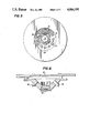
- FIG. 2 is a partial sectional view in elevation of the fiber optic probe employed in the system of FIG. 1;
- FIG. 3 is an enlarged sectional view taken along line 3--3 in FIG. 2 to show the shape of a transmitting aperture for the gloss measurement;
- FIG. 4 is an enlarged cross sectional view taken along the line 4--4 in FIG. 2 to show the shape of a receptor aperture for the gloss measurement;
- FIG. 5 is a view taken along the line 5--5 in FIG. 2 showing the top side of a fixture in the fiber optic probe;
- FIG. 6 is a sectional view in elevation taken along the line 6--6 in FIG. 2.
- the instrument of the present invention is a modification of the instrument disclosed in copending application Ser. No. 868,700 filed May 30, 1986 entitled "Spectrometer with Combined Visible and Ultraviolet Sample Illumination” and invented by the inventor of this application.
- the instrument comprises a cabinet 11 in which a source of visible light 15 is mounted to direct a beam of light through a shutter 22 onto the end of a fiber optic bundle 23, which carries the light through a flexible cable 19 to a probe 21.
- the source 15 also directs a portion of its beam onto the end of a small fiber optic bundle 33. The portion of the light directed onto the fiber optic bundle 33 does not pass through the shutter 22.
- the fiber optic bundle 23 is separated into 10 round bundles 28, the ends of which are mounted in a fixture 29, as shown in FIG. 5 and 6.
- the ends of the bundles 28 are distributed at 30 degree angles around an opening 30 in the probe, except that at two diametrically opposite positions, a 60 degree space is left between the adjacent pairs of bundle ends to leave room for the gloss measurement optics.
- the ends of the bundles 28 are arranged to direct light at an angle of 45 degrees onto the plane of the opening 30.
- a lens 32 may be mounted in the fixture 29 on the axis thereof to focus light diffusely reflected vertically from the surface of a sample placed over the opening 30 onto the end of a fiber optic bundle 25.
- the lens 32 is not needed and may be omitted from instruments designed for such large area measurements. Alternatively, the lens 32 may be made selectively removable.
- the fiber optic bundle 25 carries the received light back through the cable 19 to the cabinet 11 and into the entrance slit of a spectrometer 27 within the cabinet 11.
- the end of the fiber optic bundle 25 which transmits the light into the spectrometer 27 is shaped into the entrance slit for the spectrometer 27 and is positioned to irradiate a fixed optical grating within the spectrometer 27.
- the details of the spectrometer 27 are disclosed in the above mentioned copending application.
- the small optic fiber bundle 33 carries light from the source 15 through the cable 19 to its transmitting end, which is mounted in the probe 21 in a mounting tube 36 with the bundle 33 positioned on the axis of the mounting tube as shown in FIG. 2.
- the mounting tube 36 is mounted in the fixture 29 in the center of one of the two 60 degree spaces between adjacent bundles 28 and is oriented so that the transmitting end of the fiber optic bundle 33 is pointed at the center of the opening 30 at an angle of 60 degrees to normal to the plane of the opening 30.
- a mask 37 defining a source aperture 47 is mounted in the tube 36 spaced a small distance from the transmitting end of the fiber optic bundle 33.
- the beam of light emitted from the fiber optic bundle 33 is actually a multiplicity of separate tiny beams of light.
- the space between the end of the fiber optic bundle 33 and the mask 37 allows the tiny beams to mix together so that the aperture 47 is substantially uniformly illuminated and a uniform beam of light is projected from the aperture 47 toward the opening 30.
- the use of fiber optics to illuminate the source aperture 47 achieves a high degree of uniformity of illumination of the source aperture 47 compared to source apertures illuminated by incandescent filaments.
- Incandescent filaments tend to have variations in the light intensity emitted over the length of the filament, so that when one is used to illuminate a source aperture, some degree of non-uniformity in the intensity of the illumination over the area of the aperture occurs. More uniform illumination is achieved with the present invention because each optic fiber in the bundle 33 will emit a beam of substantially the same intensity as the other optic fibers in the bundle. Accordingly, when these beams of uniform intensity mix together at the source aperture 47, uniform illumination is achieved.
- a lens 38 to collimate light transmitted through the aperture 47 and direct the light in a beam of parallel rays toward the center of the opening 30.
- a mounting tube 40 Opposite the mounting tube 36 in the fixture 29 in the other 60 degree space between adjacent bundles 28 is a mounting tube 40, in which the end of a small fiber optic bundle 42 is mounted at the outer end of the tube 40 on the axis thereof. The end of the fiber optic bundle 42 is also pointed at the center of the opening 30 at an angle of 60 degrees to normal to the plane of the opening 30.
- a mask 49 defining a receptor aperture 48 is mounted in the tube 40 spaced a short distance from the end of the optic fiber bundle 42.
- the inner end of the mounting tube 40 contains a lens 44, which will focus light received from the center of the surface of a sample placed over the opening 30 on the aperture 48.
- the axes of the mounting tubes 36 and 40 are in a common plane, perpendicular to the plane of the opening 30, so that light from the source aperture 47 in the mask 37 irradiating the center of a sample placed over the opening 30 and specularly reflected therefrom will be focused within the receptor aperture 48 in the mask 49.
- the source aperture 47 in the mask 37 is rectangular in shape.
- Light from the fiber optic bundle 33 after passing through the source aperture 47 is caused to illuminate the sample and for a polished sample placed over the opening 30, a rectangular image of source aperture 47 is formed at the receptor aperture 48.
- the receptor aperture 48 also has a rectangular shape corresponding to the rectangular shape of the source aperture 47.
- the lens 44 focuses an image 76 in the middle of the receptor aperture 48 of the specular reflection from the spot of light illuminated on a surface of a sample placed over the opening 30 by light from the fiber optic bundle 33.
- the receptor aperture 48 must be at least as large as the image and preferably is slightly larger than the image as shown in FIG. 4. The exact sizes and ratios of the source and receptor apertures will generally correspond to those cited by such standardizing bodies as, ASTM, BSO, JIC, ISO et al.
- the shutter 22 which is controlled by a computer 69, is closed so that the only light irradiating the sample is transmitted through the small fiber optic bundle 33 and the source aperture 47.
- substantially all of the light received by the receptor aperture 48 will be specularly reflected light from the illumination of the sample surface by the fiber optic bundle 33.
- the light passing through the receptor aperture 48 is received by the fiber optic bundle 42, which carries the specularly reflected light back through the cable 19 to the cabinet 11 and into the housing of the spectrometer 27, where it is arranged to irradiate a photocell 46.
- the photocell 46 will detect the intensity of the light specularly reflected from a sample positioned over the aperture 30. Because of the uniform illumination of the source aperture achieved by the use of fiber optics, the illumination of the sample over the illuminated area is very uniform. As a result the gloss measurement is less subject to variation caused by surface irregularities.
- signals from the photodetectors of the fixed array in the spectrometer 27 are amplified by amplifiers 68 located in the housing of the spectrometer 27 and applied to the computer 69, which is referred to as the internal computer.
- One of the amplifiers 68 will amplify the output signal of the photodetector 46 and apply this amplified signal to the internal computer 69.
- the internal computer 69 is connected to an external computer 75, which provides a display of the measurements and applies signals to the internal computer 69 in response to keyboard actuation to control the operation of the instrument.
- the probe 21 has mounted therein, a stepper motor 39, which has mounted on its output shaft 41, two paddles 43 and 45.
- Paddle 43 has mounted in one end thereof a circular white standard sample approximately the same size as the opening 30 and the paddle 43 is pivotable by the stepper motor 39 via the shaft 41 to a position in which the white standard sample is aligned with the opening 30 just inside the opening 30 within the housing of the probe 21.
- the resulting amplified signals produced by the array of photodetectors in the spectrometer 27 are processed by the internal computer 69 to determine calibration factors. As explained in the above-mentioned copending application, these calibration factors are used to correct the amplified output signals from the photodetector array when an unknown sample is being measured and compensate for temperature changes.
- stepper motor 39 pivots the paddle 43 past the opening 30, it will bring the paddle 45 into position to block any light transmission between the lens 32 and the receiving end of the fiber optic bundle 25.
- the paddle 45 is opaque and is used to obtain null values for the spectrometer 27, in the manner explained in the copending application.
- the computer 69 opens the shutter 22, and immediately thereafter or therebefore, the computer 69 closes the shutter 22 to make a gloss measurement.
- the computer 69 closes the shutter 22 to make a gloss measurement.
- some light will be diffusely reflected to the receiving end of the fiber optic bundle 25 as a result of the irradiation of the sample through the optic fiber 33, but this light will be taken into account in the normal calibration of the instrument for diffuse reflectance.
- the only light transmitted to the sample surface will be through the fiber optic bundle 33. Some of this light will be diffusely reflected from the surface of the sample to the receiving end of the fiber optic bundle 42 in addition to the specularly reflected light. However, the amount of this light generally will be small relative to the intensity of the specularly reflected light and the diffusely reflected light, can be mathematically subtracted in the instrument measurements by the following relationship:
- k a fraction determined by the ratio of the diffuse energy received by the receptor aperture to that of the total diffuse hemispherical reflectance of a perfect lambertian reflector.
Abstract
Description
R.sub.s '=R.sub.s -kR.sub.D
Claims (15)
Priority Applications (2)
| Application Number | Priority Date | Filing Date | Title |
|---|---|---|---|
| US07/173,099 US4886355A (en) | 1988-03-28 | 1988-03-28 | Combined gloss and color measuring instrument |
| EP19890104696 EP0335192A3 (en) | 1988-03-28 | 1989-03-16 | Combined gloss and color measuring instrument |
Applications Claiming Priority (1)
| Application Number | Priority Date | Filing Date | Title |
|---|---|---|---|
| US07/173,099 US4886355A (en) | 1988-03-28 | 1988-03-28 | Combined gloss and color measuring instrument |
Publications (1)
| Publication Number | Publication Date |
|---|---|
| US4886355A true US4886355A (en) | 1989-12-12 |
Family
ID=22630538
Family Applications (1)
| Application Number | Title | Priority Date | Filing Date |
|---|---|---|---|
| US07/173,099 Expired - Lifetime US4886355A (en) | 1988-03-28 | 1988-03-28 | Combined gloss and color measuring instrument |
Country Status (2)
| Country | Link |
|---|---|
| US (1) | US4886355A (en) |
| EP (1) | EP0335192A3 (en) |
Cited By (28)
| Publication number | Priority date | Publication date | Assignee | Title |
|---|---|---|---|---|
| US5262840A (en) * | 1990-01-30 | 1993-11-16 | Sequa Corporation | Multispectral reflectometer |
| US5319437A (en) * | 1991-07-26 | 1994-06-07 | Kollmorgen Corporation | Handheld portable spectrophotometer |
| US5377000A (en) * | 1993-04-29 | 1994-12-27 | Color And Appearance Technology, Inc. | Portable appearance measuring apparatus |
| US5508809A (en) * | 1991-09-19 | 1996-04-16 | British Gas Plc | Optical sensor |
| US5517302A (en) * | 1990-01-30 | 1996-05-14 | Stearns; Thornton | Multispectral reflectometer |
| US5552890A (en) * | 1994-04-19 | 1996-09-03 | Tricor Systems, Inc. | Gloss measurement system |
| US5619319A (en) * | 1993-08-11 | 1997-04-08 | Sanmei Electronic Co., Ltd. | Apparatus for acquiring data used to evaluate and reproduce the color of a sample on the basis of the chroma and glossiness of the sample |
| US5636024A (en) * | 1994-10-05 | 1997-06-03 | Musco Corporation | Apparatus and method of inspection of specular and semi-specular surfaces |
| US5774209A (en) * | 1996-10-08 | 1998-06-30 | Spectronic Instruments, Inc. | Transmittance cell for spectrophotometer |
| EP1314972A1 (en) | 2001-11-26 | 2003-05-28 | Gretag-Macbeth AG | Spectrophotometer and its use |
| US6836362B2 (en) | 2001-05-14 | 2004-12-28 | General Electric Company | Method for the rapid determination of the optical quality of combinatorial libraries |
| US6842250B2 (en) * | 1999-12-23 | 2005-01-11 | Byk-Gardner Gmbh | Device for a quantified determination of the quality of surfaces |
| US20060066924A1 (en) * | 2004-09-27 | 2006-03-30 | Durst Phototechnik - A.G. | Device for generating a multicolor digital picture |
| US20060256341A1 (en) * | 2005-03-10 | 2006-11-16 | Fuji Xerox Co., Ltd | Gloss measurement apparatus and gloss measurement method |
| US20070076206A1 (en) * | 1996-01-02 | 2007-04-05 | Jung Wayne D | Apparatus and method for measuring color |
| US20070201029A1 (en) * | 2005-03-22 | 2007-08-30 | Canon Kabushiki Kaisha | Evaluating method and apparatus thereof |
| US7397562B2 (en) | 1998-07-09 | 2008-07-08 | Jjl Technologies Llc | Apparatus and method for measuring optical characteristics of an object |
| US7397541B2 (en) | 1997-01-02 | 2008-07-08 | Ssl Technologies Llc | Apparatus and method for measuring optical characteristics of an object |
| US7403285B2 (en) | 1997-07-01 | 2008-07-22 | Jjl Technologies Llc | Apparatus and method for measuring optical characteristics of an object |
| US7538878B2 (en) | 1996-01-02 | 2009-05-26 | Jjl Technologies Llc | Apparatus and method for measuring optical characteristics of an object |
| US7682150B2 (en) | 1996-01-02 | 2010-03-23 | Jjl Technologies Llc | Method for preparing a dental prosthesis based on electronically determined image and color/shade data and based on telephone communication |
| US7785103B2 (en) | 1998-06-30 | 2010-08-31 | Jjl Technologies Llc | Apparatus and method for measuring optical characteristics of teeth |
| US20130154830A1 (en) * | 2011-12-15 | 2013-06-20 | Datacolor, Inc. | System and apparatus for gloss correction in color measurements |
| US8786844B2 (en) | 1998-06-30 | 2014-07-22 | 511 Innovations, Inc. | Apparatus for measuring optical characteristics including position detection |
| EP3121588A1 (en) * | 2015-07-22 | 2017-01-25 | Canon Kabushiki Kaisha | Optical characteristic measuring apparatus |
| US20170199079A1 (en) * | 2014-05-23 | 2017-07-13 | Konica Minolta, Inc. | Surface characteristic measurement device |
| US20190285540A1 (en) * | 2016-05-31 | 2019-09-19 | Konica Minolta, Inc. | Reflection Characteristic Measuring Device |
| WO2023030861A1 (en) * | 2021-09-02 | 2023-03-09 | Byk-Gardner Gmbh | Apparatus and method for inspecting surfaces with wavelength analysis |
Families Citing this family (14)
| Publication number | Priority date | Publication date | Assignee | Title |
|---|---|---|---|---|
| DE4138679C2 (en) * | 1991-11-25 | 1998-07-23 | Helmut Dipl Ing Reiser | Device for determining visual surface properties |
| DE4243885A1 (en) * | 1992-12-23 | 1994-06-30 | Fogra Forschungsgesellschaft D | Measuring colour and sheen of specimen surface |
| DE19503763C2 (en) * | 1995-02-04 | 1996-11-28 | Honeywell Ag | Color measuring device |
| US5748221A (en) * | 1995-11-01 | 1998-05-05 | Xerox Corporation | Apparatus for colorimetry gloss and registration feedback in a color printing machine |
| EP0777113A1 (en) * | 1995-12-01 | 1997-06-04 | MHT Optic Research AG | Method and device for determination of colour value of transparent bodies |
| AU2006213964B2 (en) * | 1996-01-02 | 2008-07-03 | Jjl Technologies Llc | Apparatus and method for measuring optical characteristics of an object |
| US5745229A (en) * | 1996-01-02 | 1998-04-28 | Lj Laboratories, L.L.C. | Apparatus for determining optical characteristics of an object |
| US5926262A (en) * | 1997-07-01 | 1999-07-20 | Lj Laboratories, L.L.C. | Apparatus and method for measuring optical characteristics of an object |
| US6226085B1 (en) * | 1998-06-26 | 2001-05-01 | Gretagmacbeth Llc | Method and apparatus for surface effect characterization |
| JP3674504B2 (en) * | 2000-12-11 | 2005-07-20 | ウシオ電機株式会社 | Spectral reflectance measuring apparatus and spectral reflectance measuring method |
| FR2840990B1 (en) * | 2002-06-18 | 2005-07-29 | France Etat Ponts Chaussees | DEVICE FOR MEASURING PHOTOMETRIC CHARACTERISTICS OF A MATERIAL |
| ATE426149T1 (en) * | 2006-10-17 | 2009-04-15 | Fiat Ricerche | METHOD FOR ANALYZING THE VISIBLE COLOR AND GONIO REFLECTION OF AN OBJECT |
| US8085397B2 (en) | 2009-07-10 | 2011-12-27 | Honeywell Asca Inc. | Fiber optic sensor utilizing broadband sources |
| US20240035969A1 (en) * | 2022-07-28 | 2024-02-01 | Axalta Coating Systems Ip Co., Llc | Method and system for matching color and/or appearance of a surface |
Citations (10)
| Publication number | Priority date | Publication date | Assignee | Title |
|---|---|---|---|---|
| US3806256A (en) * | 1971-08-12 | 1974-04-23 | Paint Res Ass | Colorimeters |
| US3890049A (en) * | 1973-09-17 | 1975-06-17 | Howell Lab Inc | Glossmeter for providing a linear response corresponding to true gloss readings |
| US3998551A (en) * | 1975-11-20 | 1976-12-21 | Shigeru Suga | Device for measuring stimulus values of the color of a liquid |
| US4040743A (en) * | 1975-09-22 | 1977-08-09 | Howell Laboratories, Incorporated | Method and apparatus for measuring the brightness of pulp slurry |
| US4218144A (en) * | 1977-09-09 | 1980-08-19 | The Rank Organisation Limited | Measuring instruments |
| US4222064A (en) * | 1977-03-07 | 1980-09-09 | Nekoosa Papers Inc. | Optical property measurement system and method |
| US4319847A (en) * | 1979-12-05 | 1982-03-16 | Measurex Corporation | Apparatus to measure select properties of a moving sheet with improved standardization means |
| US4464054A (en) * | 1982-05-27 | 1984-08-07 | Pacific Scientific Company | Colorimeter instrument with fiber optic ring illuminator |
| US4669873A (en) * | 1984-02-24 | 1987-06-02 | Leybold-Heraeus Gmbh | Spectrophotometer |
| US4678325A (en) * | 1983-05-05 | 1987-07-07 | Olavi Lehtikoski | Apparatus for measuring optical properties of paper |
Family Cites Families (5)
| Publication number | Priority date | Publication date | Assignee | Title |
|---|---|---|---|---|
| US3562539A (en) * | 1968-08-28 | 1971-02-09 | Us Agriculture | Apparatus for scanning thin-layer and other chromatograms |
| US3999864A (en) * | 1975-11-17 | 1976-12-28 | International Business Machines Corporation | Gloss measuring instrument |
| FR2579884B1 (en) * | 1985-04-09 | 1988-12-02 | Sanofi Sa | |
| FI78355C (en) * | 1986-05-27 | 1989-07-10 | Puumalaisen Tutkimuslaitos Oy | METHOD FOER MAETNING AV GLANS OCH APPARATUR FOER TILLAEMPNING AV METODEN. |
| DE8704679U1 (en) * | 1987-03-30 | 1987-05-27 | Fa. Carl Zeiss, 7920 Heidenheim, De |
-
1988
- 1988-03-28 US US07/173,099 patent/US4886355A/en not_active Expired - Lifetime
-
1989
- 1989-03-16 EP EP19890104696 patent/EP0335192A3/en not_active Withdrawn
Patent Citations (10)
| Publication number | Priority date | Publication date | Assignee | Title |
|---|---|---|---|---|
| US3806256A (en) * | 1971-08-12 | 1974-04-23 | Paint Res Ass | Colorimeters |
| US3890049A (en) * | 1973-09-17 | 1975-06-17 | Howell Lab Inc | Glossmeter for providing a linear response corresponding to true gloss readings |
| US4040743A (en) * | 1975-09-22 | 1977-08-09 | Howell Laboratories, Incorporated | Method and apparatus for measuring the brightness of pulp slurry |
| US3998551A (en) * | 1975-11-20 | 1976-12-21 | Shigeru Suga | Device for measuring stimulus values of the color of a liquid |
| US4222064A (en) * | 1977-03-07 | 1980-09-09 | Nekoosa Papers Inc. | Optical property measurement system and method |
| US4218144A (en) * | 1977-09-09 | 1980-08-19 | The Rank Organisation Limited | Measuring instruments |
| US4319847A (en) * | 1979-12-05 | 1982-03-16 | Measurex Corporation | Apparatus to measure select properties of a moving sheet with improved standardization means |
| US4464054A (en) * | 1982-05-27 | 1984-08-07 | Pacific Scientific Company | Colorimeter instrument with fiber optic ring illuminator |
| US4678325A (en) * | 1983-05-05 | 1987-07-07 | Olavi Lehtikoski | Apparatus for measuring optical properties of paper |
| US4669873A (en) * | 1984-02-24 | 1987-06-02 | Leybold-Heraeus Gmbh | Spectrophotometer |
Non-Patent Citations (2)
| Title |
|---|
| Budde, "A Reference Instrument for 20°, 60° and 85° Gloss Measurements", Metrologia 16, 1980, pp. 1-5. |
| Budde, A Reference Instrument for 20 , 60 and 85 Gloss Measurements , Metrologia 16, 1980, pp. 1 5. * |
Cited By (41)
| Publication number | Priority date | Publication date | Assignee | Title |
|---|---|---|---|---|
| US5262840A (en) * | 1990-01-30 | 1993-11-16 | Sequa Corporation | Multispectral reflectometer |
| US5517302A (en) * | 1990-01-30 | 1996-05-14 | Stearns; Thornton | Multispectral reflectometer |
| US5319437A (en) * | 1991-07-26 | 1994-06-07 | Kollmorgen Corporation | Handheld portable spectrophotometer |
| US5483339A (en) * | 1991-07-26 | 1996-01-09 | Killmorgen Corporation | Spectrophotometer and radiometric measurement apparatus |
| US5508809A (en) * | 1991-09-19 | 1996-04-16 | British Gas Plc | Optical sensor |
| US5377000A (en) * | 1993-04-29 | 1994-12-27 | Color And Appearance Technology, Inc. | Portable appearance measuring apparatus |
| US5619319A (en) * | 1993-08-11 | 1997-04-08 | Sanmei Electronic Co., Ltd. | Apparatus for acquiring data used to evaluate and reproduce the color of a sample on the basis of the chroma and glossiness of the sample |
| US5552890A (en) * | 1994-04-19 | 1996-09-03 | Tricor Systems, Inc. | Gloss measurement system |
| US5636024A (en) * | 1994-10-05 | 1997-06-03 | Musco Corporation | Apparatus and method of inspection of specular and semi-specular surfaces |
| US20070076206A1 (en) * | 1996-01-02 | 2007-04-05 | Jung Wayne D | Apparatus and method for measuring color |
| US8817243B2 (en) | 1996-01-02 | 2014-08-26 | 511 Innovations, Inc. | Apparatus and method for measuring color |
| US8792097B2 (en) | 1996-01-02 | 2014-07-29 | 511 Innovations, Inc. | Systems for applying pigment to a substrate with a spectrophotometer integral to the system |
| US8159666B2 (en) | 1996-01-02 | 2012-04-17 | Jjl Technologies Llc | Apparatus and method for measuring color |
| US7682150B2 (en) | 1996-01-02 | 2010-03-23 | Jjl Technologies Llc | Method for preparing a dental prosthesis based on electronically determined image and color/shade data and based on telephone communication |
| US7538878B2 (en) | 1996-01-02 | 2009-05-26 | Jjl Technologies Llc | Apparatus and method for measuring optical characteristics of an object |
| US7400404B2 (en) | 1996-01-02 | 2008-07-15 | Jjl Technologies Llc | Apparatus and method for measuring color |
| US5774209A (en) * | 1996-10-08 | 1998-06-30 | Spectronic Instruments, Inc. | Transmittance cell for spectrophotometer |
| US8998613B2 (en) | 1997-01-02 | 2015-04-07 | 511 Innovations Inc. | Apparatus and method for measuring optical characteristics using a camera and a calibration chart imaged with the camera |
| US8472012B2 (en) | 1997-01-02 | 2013-06-25 | Jjl Technologies Llc | Apparatus having a first optical sensor making a first measurement to detect position and a second optical sensor making a second measurement |
| US7397541B2 (en) | 1997-01-02 | 2008-07-08 | Ssl Technologies Llc | Apparatus and method for measuring optical characteristics of an object |
| US7403285B2 (en) | 1997-07-01 | 2008-07-22 | Jjl Technologies Llc | Apparatus and method for measuring optical characteristics of an object |
| US8786844B2 (en) | 1998-06-30 | 2014-07-22 | 511 Innovations, Inc. | Apparatus for measuring optical characteristics including position detection |
| US7785103B2 (en) | 1998-06-30 | 2010-08-31 | Jjl Technologies Llc | Apparatus and method for measuring optical characteristics of teeth |
| US7397562B2 (en) | 1998-07-09 | 2008-07-08 | Jjl Technologies Llc | Apparatus and method for measuring optical characteristics of an object |
| US6842250B2 (en) * | 1999-12-23 | 2005-01-11 | Byk-Gardner Gmbh | Device for a quantified determination of the quality of surfaces |
| US6836362B2 (en) | 2001-05-14 | 2004-12-28 | General Electric Company | Method for the rapid determination of the optical quality of combinatorial libraries |
| EP1314972A1 (en) | 2001-11-26 | 2003-05-28 | Gretag-Macbeth AG | Spectrophotometer and its use |
| US20060066924A1 (en) * | 2004-09-27 | 2006-03-30 | Durst Phototechnik - A.G. | Device for generating a multicolor digital picture |
| US7679747B2 (en) * | 2005-03-10 | 2010-03-16 | Fuji Xerox Co., Ltd. | Gloss measurement apparatus and gloss measurement method |
| US20060256341A1 (en) * | 2005-03-10 | 2006-11-16 | Fuji Xerox Co., Ltd | Gloss measurement apparatus and gloss measurement method |
| US20070201029A1 (en) * | 2005-03-22 | 2007-08-30 | Canon Kabushiki Kaisha | Evaluating method and apparatus thereof |
| US7315379B2 (en) * | 2005-03-22 | 2008-01-01 | Canon Kabushiki Kaisha | Evaluating method and apparatus thereof |
| US8680993B2 (en) * | 2011-12-15 | 2014-03-25 | Datacolor Holding Ag | System and apparatus for gloss correction in color measurements |
| US20130154830A1 (en) * | 2011-12-15 | 2013-06-20 | Datacolor, Inc. | System and apparatus for gloss correction in color measurements |
| US20170199079A1 (en) * | 2014-05-23 | 2017-07-13 | Konica Minolta, Inc. | Surface characteristic measurement device |
| US9976905B2 (en) * | 2014-05-23 | 2018-05-22 | Konica Minolta, Inc. | Surface characteristic measurement device |
| EP3121588A1 (en) * | 2015-07-22 | 2017-01-25 | Canon Kabushiki Kaisha | Optical characteristic measuring apparatus |
| US10697887B2 (en) | 2015-07-22 | 2020-06-30 | Canon Kabushiki Kaisha | Optical characteristic measuring apparatus |
| US20190285540A1 (en) * | 2016-05-31 | 2019-09-19 | Konica Minolta, Inc. | Reflection Characteristic Measuring Device |
| US10746650B2 (en) * | 2016-05-31 | 2020-08-18 | Konica Minolta, Inc. | Reflection characteristic measuring device |
| WO2023030861A1 (en) * | 2021-09-02 | 2023-03-09 | Byk-Gardner Gmbh | Apparatus and method for inspecting surfaces with wavelength analysis |
Also Published As
| Publication number | Publication date |
|---|---|
| EP0335192A3 (en) | 1990-12-27 |
| EP0335192A2 (en) | 1989-10-04 |
Similar Documents
| Publication | Publication Date | Title |
|---|---|---|
| US4886355A (en) | Combined gloss and color measuring instrument | |
| US4919535A (en) | Reflectance measuring apparatus for making contactless measurements | |
| US4932779A (en) | Color measuring instrument with integrating sphere | |
| EP0569104B1 (en) | Portable spectrophotometer | |
| US4756619A (en) | Reflectance measuring apparatus for making contactless measurements | |
| US5040889A (en) | Spectrometer with combined visible and ultraviolet sample illumination | |
| KR100242670B1 (en) | Method and device for spectral remission and transmission measurement | |
| US3999864A (en) | Gloss measuring instrument | |
| US4487504A (en) | Reflectance measuring instrument with integrating sphere | |
| US5035508A (en) | Light absorption analyser | |
| GB2189623A (en) | Remote reading spectrophotometer | |
| US6088117A (en) | Reflection characteristic measuring apparatus | |
| US4565444A (en) | Electronically scanned spectrometer color, brightness and opacity measurement and control system | |
| JPS628729B2 (en) | ||
| KR100521616B1 (en) | Spectral reflectance measuring apparatus and spectral reflectance measuring method | |
| US5155628A (en) | Optical transmission spectrometer | |
| US6862085B2 (en) | Device for detecting transmission losses by means of measurements | |
| HU190892B (en) | Aparatus for measuring reflection of the planar surfaces, in particular fluckering meter | |
| JPS61292043A (en) | Photodetecting probe for spectocolorimeter | |
| US7321423B2 (en) | Real-time goniospectrophotometer | |
| HU188795B (en) | Detecting arrangement for meassuring the intensity of radiation scattering at a given angle from a sample exposed to radiation of given angle of incidence | |
| JPH02114151A (en) | Refractometer having aperture distribution depending upon refractive index | |
| US5392125A (en) | Instrument for determining visual surface properties | |
| JP2898489B2 (en) | Equipment for spectrophotometric analysis | |
| JPH10137194A (en) | Surface color measuring apparatus, luster measuring apparatus and spectral colorimetric apparatus |
Legal Events
| Date | Code | Title | Description |
|---|---|---|---|
| AS | Assignment |
Owner name: PACIFIC SCIENTIFIC COMPANY, 1350 SOUTH STATE COLLE Free format text: ASSIGNMENT OF ASSIGNORS INTEREST.;ASSIGNOR:KEANE, THOMAS J.;REEL/FRAME:004878/0462 Effective date: 19880321 Owner name: PACIFIC SCIENTIFIC COMPANY, A CORPORATION OF CALIF Free format text: ASSIGNMENT OF ASSIGNORS INTEREST;ASSIGNOR:KEANE, THOMAS J.;REEL/FRAME:004878/0462 Effective date: 19880321 |
|
| AS | Assignment |
Owner name: BYK GARDNER, INC., MARYLAND Free format text: ASSIGNS THE INTIRE INTEREST, EFFICTIVE AS OF 2/27/89;ASSIGNOR:PACIFIC SCIENTIFIC COMPANY, A CORP. OF CA;REEL/FRAME:005092/0184 Effective date: 19890414 |
|
| STCF | Information on status: patent grant |
Free format text: PATENTED CASE |
|
| FEPP | Fee payment procedure |
Free format text: PAYOR NUMBER ASSIGNED (ORIGINAL EVENT CODE: ASPN); ENTITY STATUS OF PATENT OWNER: LARGE ENTITY |
|
| FPAY | Fee payment |
Year of fee payment: 4 |
|
| AS | Assignment |
Owner name: BYK -GARDNER USA, DIVISION OF ALTANA INC.,, NEW YO Free format text: ASSIGNMENT OF ASSIGNORS INTEREST;ASSIGNOR:BYK GARDNER, INC.;REEL/FRAME:007058/0672 Effective date: 19940630 |
|
| FPAY | Fee payment |
Year of fee payment: 8 |
|
| FPAY | Fee payment |
Year of fee payment: 12 |