US4887805A - Top vacuum corrugation feeder - Google Patents
Top vacuum corrugation feeder Download PDFInfo
- Publication number
- US4887805A US4887805A US07/166,281 US16628188A US4887805A US 4887805 A US4887805 A US 4887805A US 16628188 A US16628188 A US 16628188A US 4887805 A US4887805 A US 4887805A
- Authority
- US
- United States
- Prior art keywords
- sheet
- stack
- sheets
- vacuum
- air knife
- Prior art date
- Legal status (The legal status is an assumption and is not a legal conclusion. Google has not performed a legal analysis and makes no representation as to the accuracy of the status listed.)
- Expired - Lifetime
Links
- 238000000926 separation method Methods 0.000 claims description 15
- 230000005611 electricity Effects 0.000 claims description 3
- 230000003068 static effect Effects 0.000 claims description 3
- 239000002184 metal Substances 0.000 claims description 2
- 230000000284 resting effect Effects 0.000 abstract 1
- 239000000463 material Substances 0.000 description 16
- 230000032258 transport Effects 0.000 description 16
- 238000012546 transfer Methods 0.000 description 7
- 229910003460 diamond Inorganic materials 0.000 description 5
- 239000010432 diamond Substances 0.000 description 5
- 230000007246 mechanism Effects 0.000 description 5
- 230000036961 partial effect Effects 0.000 description 5
- 108091008695 photoreceptors Proteins 0.000 description 5
- 230000000694 effects Effects 0.000 description 4
- 238000000034 method Methods 0.000 description 4
- 230000009467 reduction Effects 0.000 description 3
- 241000237858 Gastropoda Species 0.000 description 2
- 230000009471 action Effects 0.000 description 2
- 229920001971 elastomer Polymers 0.000 description 2
- 230000008030 elimination Effects 0.000 description 2
- 238000003379 elimination reaction Methods 0.000 description 2
- 230000005484 gravity Effects 0.000 description 2
- 238000012986 modification Methods 0.000 description 2
- 230000004048 modification Effects 0.000 description 2
- 230000002441 reversible effect Effects 0.000 description 2
- 238000007788 roughening Methods 0.000 description 2
- 238000003860 storage Methods 0.000 description 2
- 241000212384 Bifora Species 0.000 description 1
- 230000003213 activating effect Effects 0.000 description 1
- 238000007792 addition Methods 0.000 description 1
- 238000004026 adhesive bonding Methods 0.000 description 1
- 238000004140 cleaning Methods 0.000 description 1
- 230000008602 contraction Effects 0.000 description 1
- 238000012937 correction Methods 0.000 description 1
- 230000008878 coupling Effects 0.000 description 1
- 238000010168 coupling process Methods 0.000 description 1
- 238000005859 coupling reaction Methods 0.000 description 1
- 238000005520 cutting process Methods 0.000 description 1
- 230000003247 decreasing effect Effects 0.000 description 1
- 230000001934 delay Effects 0.000 description 1
- 230000001419 dependent effect Effects 0.000 description 1
- 238000009826 distribution Methods 0.000 description 1
- 239000000806 elastomer Substances 0.000 description 1
- 230000005525 hole transport Effects 0.000 description 1
- 238000003384 imaging method Methods 0.000 description 1
- 230000002401 inhibitory effect Effects 0.000 description 1
- 230000002045 lasting effect Effects 0.000 description 1
- 230000003287 optical effect Effects 0.000 description 1
- 238000012634 optical imaging Methods 0.000 description 1
- 230000002265 prevention Effects 0.000 description 1
- 230000008569 process Effects 0.000 description 1
- 238000012545 processing Methods 0.000 description 1
- 230000002829 reductive effect Effects 0.000 description 1
- 239000000758 substrate Substances 0.000 description 1
Images


Classifications
-
- B—PERFORMING OPERATIONS; TRANSPORTING
- B65—CONVEYING; PACKING; STORING; HANDLING THIN OR FILAMENTARY MATERIAL
- B65H—HANDLING THIN OR FILAMENTARY MATERIAL, e.g. SHEETS, WEBS, CABLES
- B65H3/00—Separating articles from piles
- B65H3/46—Supplementary devices or measures to assist separation or prevent double feed
- B65H3/48—Air blast acting on edges of, or under, articles
-
- B—PERFORMING OPERATIONS; TRANSPORTING
- B65—CONVEYING; PACKING; STORING; HANDLING THIN OR FILAMENTARY MATERIAL
- B65H—HANDLING THIN OR FILAMENTARY MATERIAL, e.g. SHEETS, WEBS, CABLES
- B65H3/00—Separating articles from piles
- B65H3/08—Separating articles from piles using pneumatic force
- B65H3/12—Suction bands, belts, or tables moving relatively to the pile
- B65H3/124—Suction bands or belts
- B65H3/128—Suction bands or belts separating from the top of pile
Definitions
- This invention relates to an electrophotographic printing machine, and more particularly, concerns an improved top vacuum corrugation feeder for such a machine.
- One of the sheet feeders best known for high speed operation is the top vacuum corrugation feeder with a front air knife.
- a vacuum plenum with a plurality of friction belts arranged to run over the vacuum plenum is placed at the top of a stack of sheets in a supply tray.
- an air knife is used to inject air into the stack to raise the top several sheets from the remainder of the stack.
- air is injected by the air knife toward the stack to separate the top sheet, the vacuum pulls the separated sheet up and acquires it.
- the belt transport drives the sheet forward off the stack of sheets. In this configuration, separation of the next sheet cannot take place until the top sheet has cleared the stack.
- U.S. Pat. No. 2,979,329 (Cunningham) describes a sheet feeding mechanism useful for both top and bottom feeding of sheets wherein an oscillating vacuum chamber is used to acquire and transport a sheet to be fed. In addition, an air blast is directed to the leading edge of a stack of sheets from which the sheet is to be separated and fed to assist in separating the sheets from the stack.
- U.S. Pat. No. 2,424,453 illustrates a vacuum sheet separator feeder with an air knife wherein a plurality of feed belts with holes are transported about a vacuum plenum and pressurized air is delivered to the leading edge of the stack of sheets. This is a bottom sheet feeder.
- U.S. Pat. No. 2,895,552 (Pomper et al.) illustrates a vacuum belt transport and stacking device wherein sheets which have been cut from a web are transported from the sheet supply to a sheet stacking tray. Flexible belts perforated at intervals are used to pick up the leading edge of the sheet and release the sheet over the pile for stacking.
- U.S. Pat. No. 4,157,177 illustrates another sheet stacker wherein a first belt conveyor delivers sheets in a shingled fashion and the lower reach of a second perforated belt conveyor which is above the top of the stacking magazine attracts the leading edge of the sheets.
- the device has a slide which limits the effect of perforations depending on the size of the shingled sheet.
- U.S. Pat. No. 4,268,025 (Murayoshi) describes a top sheet feeding apparatus wherein a sheet tray has a vacuum plate above the tray which has a suction hole in its bottom portion. A feed roll in the suction hole transports a sheet to a separating roll and a frictional member in contact with the separating roll.
- U.S. Pat. No. 4,451,028 discloses a top feed vacuum corrugation feeding system that employs front and back vacuum plenums.
- U.S. Pat. No. 3,182,998 (Peterson) is directed to a conveyor device that includes a belt comprising diamond shaped rubber suction cups.
- U.S. Pat. No. 3,260,520 (Sugden) is directed to a document handling apparatus that employs a vacuum feed system and a vacuum reverse feed belt adapted to separate doublets.
- FIGS. 5 and 6 disclose a document handling system that in FIGS. 5 and 6 shows a single large apetured vacuum belt having smooth grooves for optical uniformity as well as air flow uniformity.
- U.S. Pat. No. 4,627,605 discloses a top vacuum corrugation feeder that includes an air knife with fluffer jets and vectored auxiliary fluffer jets in order to assist in separating severely downcurled sheets for feeding. Knurled vacuum feed belts are included in order to provide a uniform negative pressure to sheet material once a sheet is acquired by a vacuum plenum around which the belts are mounted.
- U.S. Pat. No. 4,635,921 discloses a top vacuum corrugation feeder that includes an air knife with fluffer jets and vectored auxiliary fluffer jets in order to assist in separating severely downcurled sheets for feeding.
- U.S. Pat. No. 4,699,369 discloses a top vacuum corrugation feeder having an air knife that includes a pair of trapezoidal shaped fluffer jets.
- a top sheet feeding apparatus comprising a sheet stack support tray, feedhead means including a vacuum plenum chamber positioned over the front of a stack of sheets when sheets are placed in the tray with the vacuum plenum chamber having a negative pressure applied thereto at all times during a feed cycle, said vacuum plenum chamber having a sheet corrugation means mounted in the center of its bottom surface and perforated knurled feed belts associated with said vacuum plenum chamber to transport the sheets acquired by said vacuum plenum chamber in a forward direction out of the stack support tray; air knife means positioned immediately adjacent the front of said stack of sheets for applying a positive pressure to the sheet stack in order to lift and separate the upper-most sheet from the rest of the stack, said air knife means including side stack fluffer jets, trapezoidal shaped pre-separation fluffer jets, converging slot jets, and fang gate means adapted to prevent multifeeding of sheets; and rotational damper means for controlling leakage from the stack sides in order to minimize sheet f
- FIG. 1 is a schematic elevational view of an electrophotographic printing machine incorporating the features of the present invention therein.
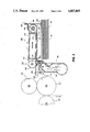
- FIG. 2 is an enlarged partial cross-sectional view of the exemplary feeder in FIG. 1 which is employed in accordance with the present invention.
- FIG. 3 is a partial front end view of the feeder shown in FIG. 2 with arrows indication the direction and path of air knife pressure flow.
- FIG. 4 is a front end view of the air knife according to the present invention.
- FIG. 5 is a partial front end view of the air knife of FIG. 3.
- FIG. 6 is a sectional plan view of the air knife shown in FIG. 4.
- FIG. 7 is a side view of the air knife shown in FIG. 4 taken along line 6--6 of FIG. 4.
- FIGS. 8A and 8B are respective plan and side view illustrations of the converging stream (FIG. 8A) and expanding air streams (FIG. 8B) which result from converging air nozzles in the air knife of FIG. 4.
- FIG. 9 is a partial front end view of the tray and feedhead of the feeder of FIG. 1.
- FIG. 1 schematically depicts the various components of an illustrative electrophotographic printing machine incorporating the top feed vacuum corrugation feeder method and apparatus of the present invention therein. It will become evident from the following discussion that the sheet feeding system disclosed herein is equally well suited for use in a wide variety of devices and is not necessarily limited to its application to the particular embodiment shown herein. For example, the apparatus of the present invention may be readily employed in nonxerographic environments and substrate transportation is general.
- the exemplary copier 10 of FIG. 1 will now be briefly described.
- the copier 10 conventionally includes a xerographic photoreceptor belt 12 and the xerographic stations acting thereon for respectively corona charging 13, image exposing 14, image developing 15, belt driving 16, precleaning discharge 17 and toner cleaning 18.
- Documents on the platen 23 maybe imaged onto the photoreceptor 12 through a variable reduction ratio optical imaging system to fit the document images to the selected size of copy sheets.
- the control of all machine functions, including all sheet feeding, is, conventionally, by the machine controller "C".
- the controller “C” is preferably a known programmable microprocessor, exemplified by the microprocessor disclosed in U.S. Pat. No. 4,166,558.
- the controller “C” conventionally controls all of the machine steps and functions described herein, and others, including the operation of the document feeder 20, all the document and copy sheet deflectors or gates, the sheet feeder drives, the finisher "F”, etc.
- the copier controller also conventionally provides for storage and comparison of the counts of the copy sheets, the number of documents recirculated in a document set, the desired number of copy sets and other selections and contols by the operator through the console or other panel of switches connected to the controller, etc.
- the controller is also programmed for time delays, jam correction control, etc.
- Conventional path sensors or switches may be utilized to help keep track of the position of the documents and the copy sheets and the moving components of the apparatus by connection to the controller.
- the controller variably regulates the various positions of the gates depending upon which mode of operation is selected.
- the copy sheets are fed from the selected one of the trays 46, 47 or 100 to the transfer station 48 for the conventional transfer of the xerographic toner image of document images from the photoreceptor 12 to the first side of a copy sheet.
- the copy sheets are then fed by a vacuum transport to a roll fuser 49 for the fusing of that toner image thereon. From the fuser, the copy sheets are fed through a sheet decurler 50.
- the copy sheets then turn a 90° corner path 54 in the sheet path which inverts the copy sheets into a last-printed face-up orientation before reaching a pivotal decision gate 56.
- the image side which has just been transferred and fused is face-up at this point.
- the duplex tray 60 provide intermediate or buffer storage for those copy sheets which have been printed on one side and on which it is desired to subsequently print an image or images on the opposite side thereof, i.e. copy sheets in the process of being duplexed. Due to the sheet inverting by the roller 58, these buffer set copy sheets are stacked into the duplex tray 60 face-down. They are stacked in this duplex tray 60 on top of one another in the order in which they were copied.
- the previously simplexed copy sheets in the tray 60 are fed seriatim by its bottom feeder 62 back to the transfer station 48 for the imaging of their second or opposite side page image.
- This is through basically the same copy sheet transport path (paper path) 64 as is provided for the clean (blank) sheets from the trays 46, 47 or 100.
- paper path paper path
- this copy sheet feed path 64 between the duplex tray 60 and the transfer station 48 has an inherent inversion which inverts the copy sheets once.
- due to the inverting transport 58 having previously stacked these buffer sheets printed face-down in the duplex tray 60 they are represented to the photoreceptor 12 at the transfer station 48 in the proper orientation, i.e.
- the output path 57 here transports the printed copy sheets directly, one at a time, into the connecting, on-line, modular, finishing station module "F". There the completed precollated copy sets may be finished by stapling, stitching, gluing, binding, and/or offset stacking. Suitable details are disclosed in the cited art, or other art, or in the applications cross-referenced hereinabove.
- FIGS. 2 and 3 show a system employing the high capacity feeder 100 of the present invention in a copy sheet feeding mode.
- the sheet feeder may be mounted for feeding document sheets to the platen of a printing machine.
- the sheet feeder 100 is provided with a conventional elevator mechanism (not shown) for raising and lowering either tray 40 or platform 42.
- a drive motor is actuated to move the sheet stack support platform 42 vertically by a stack height sensor 114 positioned above the rear of the stack when the level of sheets relative to the sensor falls below a first predetermined level.
- the drive motor is deactuated by the stack height sensor when the level of the sheets relative to the sensor is above a predetermined level. In this way, the level of the top sheet in the stack of sheets may be maintained within relatively narrow limits to assure proper sheet separation, acquisition and feeding.
- Vacuum corrugation feeder 100 that includes a vacuum plenum 110 is positioned over a portion of and beyond the front end of a tray 40 having copy sheets 131 stacked therein.
- Vacuum plenum 110 has a grounded metal member 119 attached to a portion of its bottom surface that is adapted to dissipate static electricity.
- Belts 117 are entrained around drive roller 130 and idler roller 124 as well as plenum 110. Belts 117 could be made into a single belt if desired. Perforations 118 in the belts allow a suitable vacuum source (not shown) to apply a vacuum through plenum 110 and belts 117 to acquire sheets 131 from stack 113.
- the feeder uses a system of low inertia hardware, a take away jam switch 115, and a drag brake 122 to control the precise stopping position of the belts 117.
- the belt stopping position consistency gained with this system minimizes belt coast and as a result contributes to stopping misfeeding and shingling of sheets.
- Air knife 180 applies a positive pressure to the front as well as sides of stack 13 to separate the top sheet in the stack and enhance its acquisition by vacuum plenum 110.
- Air knife 180 has at least one tap line 186 from positive pressure chamber 185 that leads to side fluffer jets 187 on at least one side of the stack.
- the side fluffer jets 187 assist in the acquisition of heavy weight paper.
- the side fluffer jets are on both sides of the stack.
- the plenum geometry of air knife 180 as shown in FIG. 3 produces a laminar flow out of the system as shown by the arrows in FIG. 3.
- the plenum geometry induces uniform pressure distribution from the pre-acquisition separation jets, and a stable flow field form the separation jets as will be described with reference to FIGS. 4-7 hereinafter. As seen in FIG.
- air pressure in plenum 183 is directed against interior walls, some of which are at angles that interfere with the air flow, before exiting the knife.
- the air is directed against the bottom of the feedhead of the vacuum corrugation feeder with a portion of the air being deflected by the feedhead toward and away from the stack of sheets in tray 40 with the portion of the air deflected toward the stack serving to fluff the top sheets in the stack and separate sheet one from sheet two, etc.
- a damper member 160 which is rotatable about pivot member 162 controls air leakage from the stack sides as well as controls the level of instability when 13# and 16# paper is fed. Damper member 160 which lights due to gravity lightly against the top of the sheet stack 13 stops sheets from fluttering which could cause multifeeds. The damper member is also useful when feeding curled sheets.
- Air knife 180 is also turned ON and applies air pressure to the front of the stack to insure separation of sheet 2 from any other sheets and assist the vacuum plenum in lifting the front end of the sheet up against corrugation rail 176 which is an additional means of insuring against multi-sheet feeding.
- Air knife 80 may be either left continuously “ON” or valved “ON” and “OFF” during appropriate times in the feed cycle. Lightweight flimsy sheet feeding is enhanced with this method of feeding since sheet 2 is easily adhered to the vacuum plenum while sheet 1 is being fed by transport rollers 125, 127 and 128. Also, gravity will conform the front and rear portions of sheet 2 against the stack while the concavity produced in the sheet by the vacuum plenum remains.
- a plurality of feed belts 117 supported for movement on rollers.
- a vacuum plenum 110 Spaced within the run of belts 117 is a vacuum plenum 110 having an opening therein adapted for cooperation with perforations 118 in the belts to provide a vacuum for pulling the top sheet in the stack onto the belts 117.
- the plenum is provided with a centrally located projecting portion 176 so that upon capture of the top sheet in the stack by the belts a corrugation will be produced in the sheet.
- the sheet is corrugated in a double valley configuration.
- the flat surfaces of the vacuum belts on each side of the projecting portion of the vacuum plenum generates a region of maximum stress in the sheet which, varies with the beam strength of the sheet.
- the second sheet resists the corrugation action, thus gaps are opened between sheets 1 and 2 which extend to their lead edges.
- the gaps and channels reduce the vacuum levels between sheets 1 and 2 due to porosity in sheet 1 and provide for entry of the separating air flow of the air knife 80.
- valving and controls it is desirable to provide a delay between the time the vacuum is applied to pull the document up to the feed belts and the start up of the belts to assure that the top sheet in the stack is captured before belt movement commences and to allow time for the air knife to separate sheet 1 from sheet 2 or any other sheets that were pulled up.
- belts 117 improves the coupling between the sheet materials and the vacuum belts by roughening or knurling the elastomer surface of the belts. As a result, a more uniform vacuum force is applied over the entire sheet area compared to the force localized to the regions of the belt holes with a smooth belt. In effect, roughening the surface of the belts, and using a diamond knurl pattern, allows a more uniform, higher average pressure differential to exist across the sheet material for the same heretofore used sealed port pressure, which increases the drive force.
- a vacuum corrugation feeder that includes a unique air knife assembly that includes an elastomeric fang gate that aids in multifeed prevention, a feedhead assembly that consists of a vacuum plenum combined with knurled feed belts and a sheet corrugator. Included also is a rotational damper member that aids in feeding curled sheets and reduces sheet flutter that might contribute to multifeeds, and a valveless system that reduces overall cost of the system and improves overall sheet acquisition time, plus elimination of known reliability problems associated with valves and solenoids. Operation of the vacuum plenum such that it is ON all the time without valving allows faster throughput of copy sheets or documents through the apparatus.
- a belt coast control means assist in precise stopping of feedbelts and thereby contributes to a reduction in multifeeding of sheets.
Abstract
Description
Claims (4)
Priority Applications (2)
| Application Number | Priority Date | Filing Date | Title |
|---|---|---|---|
| US07/166,281 US4887805A (en) | 1988-03-10 | 1988-03-10 | Top vacuum corrugation feeder |
| CA000587615A CA1317325C (en) | 1988-03-10 | 1989-01-05 | Top vacuum corrugation feeder |
Applications Claiming Priority (1)
| Application Number | Priority Date | Filing Date | Title |
|---|---|---|---|
| US07/166,281 US4887805A (en) | 1988-03-10 | 1988-03-10 | Top vacuum corrugation feeder |
Publications (1)
| Publication Number | Publication Date |
|---|---|
| US4887805A true US4887805A (en) | 1989-12-19 |
Family
ID=22602603
Family Applications (1)
| Application Number | Title | Priority Date | Filing Date |
|---|---|---|---|
| US07/166,281 Expired - Lifetime US4887805A (en) | 1988-03-10 | 1988-03-10 | Top vacuum corrugation feeder |
Country Status (2)
| Country | Link |
|---|---|
| US (1) | US4887805A (en) |
| CA (1) | CA1317325C (en) |
Cited By (40)
| Publication number | Priority date | Publication date | Assignee | Title |
|---|---|---|---|---|
| EP0446889A2 (en) * | 1990-03-13 | 1991-09-18 | Sharp Kabushiki Kaisha | Sheet feeding apparatus |
| US5050853A (en) * | 1989-03-28 | 1991-09-24 | Oce-Nederland B.V. | Device for discharging sheets from the bottom of a stack |
| EP0465062A1 (en) * | 1990-06-21 | 1992-01-08 | Xerox Corporation | Top sheet vacuum corrugation feeder with aerodynamic drag separation |
| US5090676A (en) * | 1988-09-19 | 1992-02-25 | Hitachi, Ltd. | Method of and apparatus for separating and feeding sheets |
| EP0480810A1 (en) * | 1990-10-10 | 1992-04-15 | LA POSTE, Exploitant public | Depilinghead for flat objects, in particular for objects like letters or envelopes |
| US5135213A (en) * | 1990-10-15 | 1992-08-04 | Xerox Corporation | Apparatus for method for high speed sheet feeding |
| US5150892A (en) * | 1990-03-30 | 1992-09-29 | Minolta Camera Kabushiki Kaisha | Sheet feeding apparatus |
| US5181710A (en) * | 1990-03-20 | 1993-01-26 | Sharp Kabushiki Kaisha | Top sheet feeding apparatus |
| US5184812A (en) * | 1990-05-09 | 1993-02-09 | Sharp Kabushiki Kaisha | Sheet feeding apparatus capable of feeding sheets of plural sizes |
| US5238382A (en) * | 1991-08-20 | 1993-08-24 | Highland Supply Corporation | Sheet fed article forming system |
| US5247337A (en) * | 1992-06-18 | 1993-09-21 | Xerox Corporation | Method and apparatus for copy sheet feed timed imaging registration system |
| US5328165A (en) * | 1989-03-17 | 1994-07-12 | Guy Martin | Device for the take-up of plane sheets with peel-off by turbulent air flow |
| US5344133A (en) * | 1993-02-25 | 1994-09-06 | Eastman Kodak Company | Vacuum belt feeder having a positive air pressure separator and method of using a vacuum belt feeder |
| US5454556A (en) * | 1994-01-06 | 1995-10-03 | Xerox Corporation | Curl detection through pneumatic acquisition sensing |
| EP0747311A2 (en) * | 1995-06-07 | 1996-12-11 | Hunter Douglas International Nv | Strip conveyor and stacker |
| US5707056A (en) * | 1995-09-28 | 1998-01-13 | Xerox Corporation | Variable ratio feedhead plenum |
| US5795281A (en) * | 1996-07-17 | 1998-08-18 | Southpac Trust International, Inc. | Apparatus and method for automatically forming an article |
| US5876030A (en) * | 1996-05-03 | 1999-03-02 | Eastman Kodak Company | Apparatus for facilitating handling tab stock in a top feed vacuum corrugated feeder |
| US5885595A (en) * | 1996-05-13 | 1999-03-23 | Elizabeth Arden Co., Division Of Conopco, Inc. | Cosmetic composition with a retinol fatty acid ester |
| US5899449A (en) * | 1997-01-21 | 1999-05-04 | Xerox Corporation | Top vacuum corrugation feeder with articulating suction fingers |
| US6082727A (en) * | 1997-01-21 | 2000-07-04 | Xerox Corporation | Top vacuum corrugation feeder with active retard separation mechanism |
| US6120016A (en) * | 1995-03-18 | 2000-09-19 | Watkiss Automation Limited | Apparatus for feeding sheet material |
| EP1197451A2 (en) * | 2000-10-14 | 2002-04-17 | Heidelberger Druckmaschinen Aktiengesellschaft | Method for controlling an air knife and the vacuum for improving paper pick up in a vacuum paper feed system |
| US6425580B1 (en) * | 1999-11-08 | 2002-07-30 | Sharp Kabushiki Kaisha | Recording medium transportation apparatus |
| WO2002062685A1 (en) * | 2001-02-07 | 2002-08-15 | Silverbrook Research Pty. Ltd. | Method of separating a sheet of print media from a stack of sheets |
| WO2002066349A1 (en) * | 2001-02-19 | 2002-08-29 | Silverbrook Research Pty. Ltd. | Apparatus for separating a sheet of print media from a stack of sheets |
| NL1018462C2 (en) * | 2001-07-04 | 2003-01-08 | Antonius Adrianus Arnold Smits | Mechanism for separating lowest sheet in stack of flexible plastic sheets, uses jet of air to lift stack up while lowest sheet is drawn out |
| US20030230843A1 (en) * | 2002-06-13 | 2003-12-18 | Xerox Corporation. | Rear jet air knife |
| US20040041328A1 (en) * | 2002-08-29 | 2004-03-04 | Xerox Corporation | Sheet feeding apparatus having an adaptive air fluffer |
| DE10315648A1 (en) * | 2003-04-04 | 2004-10-14 | Heidelberger Druckmaschinen Ag | Device for the sheet-by-sheet feeding of sheet-shaped printing materials from a stack to a transport path entrance |
| US20040217540A1 (en) * | 2001-06-20 | 2004-11-04 | Dan Sinai | Apparatus and method for dispensing sheets |
| WO2005047150A1 (en) * | 2003-11-17 | 2005-05-26 | Silverbrook Research Pty Ltd | Print media feed arrangement for a printer |
| US20060267264A1 (en) * | 2005-05-27 | 2006-11-30 | Ricoh Printing Systems, Ltd. | Sheet feed apparatus |
| US20060273942A1 (en) * | 2005-06-03 | 2006-12-07 | General Electric Company | Linearization system and method |
| WO2008020039A2 (en) | 2006-08-16 | 2008-02-21 | Action Medicines, S.L. | 2,5-dihydroxybenzene compounds for treating cancers and hematological dyscrasias |
| CN100462294C (en) * | 2002-09-20 | 2009-02-18 | 佳能株式会社 | Paper feeder and image forming device |
| US20100123281A1 (en) * | 2008-11-18 | 2010-05-20 | Konica Minolta Business Technologies, Inc. | Sheet supply device and image forming apparatus |
| US20120224012A1 (en) * | 2011-03-03 | 2012-09-06 | Takahiro Inoue | Sheet conveying device and ink jet recording apparatus |
| US10233042B1 (en) | 2018-01-22 | 2019-03-19 | Xerox Corporation | Top vacuum corrugation feeder with adjustable fluffer nozzles for enhanced feeding of specialty sheets |
| US11390475B2 (en) * | 2019-03-20 | 2022-07-19 | Ricoh Company, Ltd. | Sheet separation device and image forming apparatus incorporating same |
Citations (30)
| Publication number | Priority date | Publication date | Assignee | Title |
|---|---|---|---|---|
| US868317A (en) * | 1904-12-30 | 1907-10-15 | Arthur S Allen | Paper-feeding mechanism. |
| US1721608A (en) * | 1927-08-11 | 1929-07-23 | Dexter Folder Co | Sheet feeder |
| US1867038A (en) * | 1929-11-27 | 1932-07-12 | Miller Printing Machinery Co | Sheet separating device |
| US2224802A (en) * | 1938-05-30 | 1940-12-10 | Spless Georg | Device for lifting the uppermost sheet from a pile |
| US2594373A (en) * | 1950-03-03 | 1952-04-29 | Christensen Machine Co | Sheet separator air blast nozzle |
| US2895552A (en) * | 1955-08-10 | 1959-07-21 | John Waldron Corp | Transverse web cutting apparatus having sheet delivery mechanism using timed vacuum belts |
| US2979329A (en) * | 1956-12-24 | 1961-04-11 | Ibm | Paper feeding mechanism |
| US3031067A (en) * | 1960-02-09 | 1962-04-24 | Jr Ralph Polk | Apparatus for processing fruit |
| US3086771A (en) * | 1959-03-17 | 1963-04-23 | Bull Sa Machines | Sheet feeding apparatus |
| US3171647A (en) * | 1961-09-23 | 1965-03-02 | Deritend Eng Co | Suction feed mechanism for cardboard and like blanks |
| US3182988A (en) * | 1962-06-07 | 1965-05-11 | Newport News S & D Co | Welding fixture |
| US3260520A (en) * | 1964-03-09 | 1966-07-12 | Gen Electric | Document handling apparatus |
| US3424453A (en) * | 1965-08-30 | 1969-01-28 | Mohawk Data Sciences Corp | Card picker mechanism |
| US3614089A (en) * | 1969-06-16 | 1971-10-19 | Copystatics Mfg Corp | Automatic original feeder for copying machine |
| US3770266A (en) * | 1971-08-23 | 1973-11-06 | Billco Mfg Inc | Handling sheet material |
| US3837639A (en) * | 1973-06-22 | 1974-09-24 | Sperry Rand Corp | Free jet record separator |
| US3861668A (en) * | 1973-10-23 | 1975-01-21 | Vernon Wood | Sheet registration apparatus for printing machine |
| US4157177A (en) * | 1975-12-10 | 1979-06-05 | Dr. Otto C. Strecker Kg. | Apparatus for converting a stream of partly overlapping sheets into a stack |
| US4268025A (en) * | 1978-11-21 | 1981-05-19 | Ricoh Company, Ltd. | Sheet feeding apparatus |
| US4269406A (en) * | 1979-10-03 | 1981-05-26 | Xerox Corporation | Document handler |
| US4306684A (en) * | 1979-12-04 | 1981-12-22 | American Can Company | Low noise air nozzle |
| US4382593A (en) * | 1980-08-04 | 1983-05-10 | International Business Machines Corporation | Vacuum document feeder |
| US4397459A (en) * | 1981-03-16 | 1983-08-09 | Xerox Corporation | Apparatus for detecting the flotation level in an air supported sheet separating and feeding device |
| US4418905A (en) * | 1981-11-02 | 1983-12-06 | Xerox Corporation | Sheet feeding apparatus |
| US4451028A (en) * | 1981-11-27 | 1984-05-29 | Xerox Corporation | Sheet feeding apparatus |
| US4589647A (en) * | 1984-11-29 | 1986-05-20 | Xerox Corporation | Top vacuum corrugation feeder with a valveless feedhead |
| US4596385A (en) * | 1984-09-27 | 1986-06-24 | Xerox Corporation | Top vacuum corrugation feeder with moveable air blocking vane |
| US4627605A (en) * | 1985-11-06 | 1986-12-09 | Xerox Corporation | Front air knife top vacuum corrugation feeder |
| US4635921A (en) * | 1985-11-06 | 1987-01-13 | Xerox Corporation | Front air knife top vacuum corrugation feeder |
| US4699369A (en) * | 1986-06-27 | 1987-10-13 | Xerox Corporation | Front air knife improvement for a top vacuum corrugation feeder |
-
1988
- 1988-03-10 US US07/166,281 patent/US4887805A/en not_active Expired - Lifetime
-
1989
- 1989-01-05 CA CA000587615A patent/CA1317325C/en not_active Expired - Fee Related
Patent Citations (30)
| Publication number | Priority date | Publication date | Assignee | Title |
|---|---|---|---|---|
| US868317A (en) * | 1904-12-30 | 1907-10-15 | Arthur S Allen | Paper-feeding mechanism. |
| US1721608A (en) * | 1927-08-11 | 1929-07-23 | Dexter Folder Co | Sheet feeder |
| US1867038A (en) * | 1929-11-27 | 1932-07-12 | Miller Printing Machinery Co | Sheet separating device |
| US2224802A (en) * | 1938-05-30 | 1940-12-10 | Spless Georg | Device for lifting the uppermost sheet from a pile |
| US2594373A (en) * | 1950-03-03 | 1952-04-29 | Christensen Machine Co | Sheet separator air blast nozzle |
| US2895552A (en) * | 1955-08-10 | 1959-07-21 | John Waldron Corp | Transverse web cutting apparatus having sheet delivery mechanism using timed vacuum belts |
| US2979329A (en) * | 1956-12-24 | 1961-04-11 | Ibm | Paper feeding mechanism |
| US3086771A (en) * | 1959-03-17 | 1963-04-23 | Bull Sa Machines | Sheet feeding apparatus |
| US3031067A (en) * | 1960-02-09 | 1962-04-24 | Jr Ralph Polk | Apparatus for processing fruit |
| US3171647A (en) * | 1961-09-23 | 1965-03-02 | Deritend Eng Co | Suction feed mechanism for cardboard and like blanks |
| US3182988A (en) * | 1962-06-07 | 1965-05-11 | Newport News S & D Co | Welding fixture |
| US3260520A (en) * | 1964-03-09 | 1966-07-12 | Gen Electric | Document handling apparatus |
| US3424453A (en) * | 1965-08-30 | 1969-01-28 | Mohawk Data Sciences Corp | Card picker mechanism |
| US3614089A (en) * | 1969-06-16 | 1971-10-19 | Copystatics Mfg Corp | Automatic original feeder for copying machine |
| US3770266A (en) * | 1971-08-23 | 1973-11-06 | Billco Mfg Inc | Handling sheet material |
| US3837639A (en) * | 1973-06-22 | 1974-09-24 | Sperry Rand Corp | Free jet record separator |
| US3861668A (en) * | 1973-10-23 | 1975-01-21 | Vernon Wood | Sheet registration apparatus for printing machine |
| US4157177A (en) * | 1975-12-10 | 1979-06-05 | Dr. Otto C. Strecker Kg. | Apparatus for converting a stream of partly overlapping sheets into a stack |
| US4268025A (en) * | 1978-11-21 | 1981-05-19 | Ricoh Company, Ltd. | Sheet feeding apparatus |
| US4269406A (en) * | 1979-10-03 | 1981-05-26 | Xerox Corporation | Document handler |
| US4306684A (en) * | 1979-12-04 | 1981-12-22 | American Can Company | Low noise air nozzle |
| US4382593A (en) * | 1980-08-04 | 1983-05-10 | International Business Machines Corporation | Vacuum document feeder |
| US4397459A (en) * | 1981-03-16 | 1983-08-09 | Xerox Corporation | Apparatus for detecting the flotation level in an air supported sheet separating and feeding device |
| US4418905A (en) * | 1981-11-02 | 1983-12-06 | Xerox Corporation | Sheet feeding apparatus |
| US4451028A (en) * | 1981-11-27 | 1984-05-29 | Xerox Corporation | Sheet feeding apparatus |
| US4596385A (en) * | 1984-09-27 | 1986-06-24 | Xerox Corporation | Top vacuum corrugation feeder with moveable air blocking vane |
| US4589647A (en) * | 1984-11-29 | 1986-05-20 | Xerox Corporation | Top vacuum corrugation feeder with a valveless feedhead |
| US4627605A (en) * | 1985-11-06 | 1986-12-09 | Xerox Corporation | Front air knife top vacuum corrugation feeder |
| US4635921A (en) * | 1985-11-06 | 1987-01-13 | Xerox Corporation | Front air knife top vacuum corrugation feeder |
| US4699369A (en) * | 1986-06-27 | 1987-10-13 | Xerox Corporation | Front air knife improvement for a top vacuum corrugation feeder |
Cited By (113)
| Publication number | Priority date | Publication date | Assignee | Title |
|---|---|---|---|---|
| US5090676A (en) * | 1988-09-19 | 1992-02-25 | Hitachi, Ltd. | Method of and apparatus for separating and feeding sheets |
| US5328165A (en) * | 1989-03-17 | 1994-07-12 | Guy Martin | Device for the take-up of plane sheets with peel-off by turbulent air flow |
| US5050853A (en) * | 1989-03-28 | 1991-09-24 | Oce-Nederland B.V. | Device for discharging sheets from the bottom of a stack |
| EP0446889A3 (en) * | 1990-03-13 | 1992-11-19 | Sharp Kabushiki Kaisha | Sheet feeding apparatus |
| EP0446889A2 (en) * | 1990-03-13 | 1991-09-18 | Sharp Kabushiki Kaisha | Sheet feeding apparatus |
| US5181710A (en) * | 1990-03-20 | 1993-01-26 | Sharp Kabushiki Kaisha | Top sheet feeding apparatus |
| US5150892A (en) * | 1990-03-30 | 1992-09-29 | Minolta Camera Kabushiki Kaisha | Sheet feeding apparatus |
| US5184812A (en) * | 1990-05-09 | 1993-02-09 | Sharp Kabushiki Kaisha | Sheet feeding apparatus capable of feeding sheets of plural sizes |
| EP0465062A1 (en) * | 1990-06-21 | 1992-01-08 | Xerox Corporation | Top sheet vacuum corrugation feeder with aerodynamic drag separation |
| FR2667852A1 (en) * | 1990-10-10 | 1992-04-17 | Thieriot Didier | DEPILING HEAD FOR FLAT OBJECTS, IN PARTICULAR THE TYPE OF LETTERS OR ENVELOPES OF MAIL. |
| EP0480810A1 (en) * | 1990-10-10 | 1992-04-15 | LA POSTE, Exploitant public | Depilinghead for flat objects, in particular for objects like letters or envelopes |
| US5135213A (en) * | 1990-10-15 | 1992-08-04 | Xerox Corporation | Apparatus for method for high speed sheet feeding |
| US5407343A (en) * | 1991-08-20 | 1995-04-18 | Highland Supply Corporation | Sheet fed article forming system |
| US5238382A (en) * | 1991-08-20 | 1993-08-24 | Highland Supply Corporation | Sheet fed article forming system |
| US5484562A (en) * | 1991-08-20 | 1996-01-16 | Highland Supply Corporation | Sheet fed article forming system |
| US5247337A (en) * | 1992-06-18 | 1993-09-21 | Xerox Corporation | Method and apparatus for copy sheet feed timed imaging registration system |
| US5344133A (en) * | 1993-02-25 | 1994-09-06 | Eastman Kodak Company | Vacuum belt feeder having a positive air pressure separator and method of using a vacuum belt feeder |
| US5454556A (en) * | 1994-01-06 | 1995-10-03 | Xerox Corporation | Curl detection through pneumatic acquisition sensing |
| US6120016A (en) * | 1995-03-18 | 2000-09-19 | Watkiss Automation Limited | Apparatus for feeding sheet material |
| EP0747311A2 (en) * | 1995-06-07 | 1996-12-11 | Hunter Douglas International Nv | Strip conveyor and stacker |
| EP0747311A3 (en) * | 1995-06-07 | 1997-05-02 | Hunter Douglas International | Strip conveyor and stacker |
| US5707056A (en) * | 1995-09-28 | 1998-01-13 | Xerox Corporation | Variable ratio feedhead plenum |
| US5876030A (en) * | 1996-05-03 | 1999-03-02 | Eastman Kodak Company | Apparatus for facilitating handling tab stock in a top feed vacuum corrugated feeder |
| US5885595A (en) * | 1996-05-13 | 1999-03-23 | Elizabeth Arden Co., Division Of Conopco, Inc. | Cosmetic composition with a retinol fatty acid ester |
| US6419617B2 (en) | 1996-07-17 | 2002-07-16 | Southpac Trust International, Inc. | Apparatus and method for automatically forming an article |
| US5795281A (en) * | 1996-07-17 | 1998-08-18 | Southpac Trust International, Inc. | Apparatus and method for automatically forming an article |
| US6056679A (en) * | 1996-07-17 | 2000-05-02 | Southpac Trust International, Inc. | Apparatus and method for automatically forming an article |
| US6602173B2 (en) | 1996-07-17 | 2003-08-05 | Southpac Trust Int'l. Inc. | Apparatus and method for automatically forming an article |
| US5944646A (en) * | 1996-07-17 | 1999-08-31 | Southpac Trust International, Inc. | Apparatus and method for automatically forming an article |
| US6213926B1 (en) | 1996-07-17 | 2001-04-10 | Southpac Trust International, Inc. | Apparatus and method for automatically forming an article |
| US5899449A (en) * | 1997-01-21 | 1999-05-04 | Xerox Corporation | Top vacuum corrugation feeder with articulating suction fingers |
| US6082727A (en) * | 1997-01-21 | 2000-07-04 | Xerox Corporation | Top vacuum corrugation feeder with active retard separation mechanism |
| US6425580B1 (en) * | 1999-11-08 | 2002-07-30 | Sharp Kabushiki Kaisha | Recording medium transportation apparatus |
| EP1197451A2 (en) * | 2000-10-14 | 2002-04-17 | Heidelberger Druckmaschinen Aktiengesellschaft | Method for controlling an air knife and the vacuum for improving paper pick up in a vacuum paper feed system |
| EP1197451A3 (en) * | 2000-10-14 | 2003-11-12 | Heidelberger Druckmaschinen Aktiengesellschaft | Method for controlling an air knife and the vacuum for improving paper pick up in a vacuum paper feed system |
| US6554269B1 (en) * | 2000-10-14 | 2003-04-29 | Heidelberger Druckmashinen Ag | Airknife and vacuum control changes to improve sheet acquisition for a vacuum corrugated feed supply |
| US7874556B2 (en) | 2001-02-06 | 2011-01-25 | Silverbrook Research Pty Ltd | Printer with reversible air flow sheet picker |
| US20090194933A1 (en) * | 2001-02-06 | 2009-08-06 | Silverbrook Research Pty Ltd | Printer With Reversible Air Flow Sheet Picker |
| US20080303203A1 (en) * | 2001-02-06 | 2008-12-11 | Silverbrook Research Pty Ltd | Paper feed mechanism for a printing station |
| WO2002062685A1 (en) * | 2001-02-07 | 2002-08-15 | Silverbrook Research Pty. Ltd. | Method of separating a sheet of print media from a stack of sheets |
| US20040094888A1 (en) * | 2001-02-07 | 2004-05-20 | Silverbrook Research Pty Ltd | Apparatus for feeding sheets of media from a stack |
| US7533877B2 (en) | 2001-02-07 | 2009-05-19 | Silverbrook Research Pty Ltd | High speed printer with gas-operated sheet feeding |
| US7431281B2 (en) | 2001-02-07 | 2008-10-07 | Silverbrook Research Pty Ltd | Method of separating a sheet of print media from a stack of sheets |
| US20040032078A1 (en) * | 2001-02-07 | 2004-02-19 | Silverbrook Research Pty Ltd | Print media feed alignment mechanism |
| US20070284806A1 (en) * | 2001-02-07 | 2007-12-13 | Silverbrook Research Pty Ltd | Media Feed Assembly For A Printing Device |
| US7243916B2 (en) | 2001-02-07 | 2007-07-17 | Silverbrook Research Pty Ltd | Apparatus for feeding sheets of media from a stack |
| US20040070135A1 (en) * | 2001-02-07 | 2004-04-15 | Jensen David William | Method of separating a sheet of print media from a stack of sheets |
| US20070114711A9 (en) * | 2001-02-07 | 2007-05-24 | Jensen David W | Apparatus for feeding sheets of media from a stack |
| US20070108695A9 (en) * | 2001-02-07 | 2007-05-17 | Jensen David W | Media feed mechanism for feeding sheets of porous media from a stack |
| US7032899B2 (en) | 2001-02-07 | 2006-04-25 | Silverbrook Research Pty Ltd | Print media feed alignment mechanism |
| US6619654B2 (en) | 2001-02-07 | 2003-09-16 | Silverbrook Research Pty Ltd. | Method of separating a sheet of print media from a stack of sheets |
| US20040100011A1 (en) * | 2001-02-07 | 2004-05-27 | Jensen David William | Printing assembly for printing on sheets of media from a stack |
| US20040130090A1 (en) * | 2001-02-07 | 2004-07-08 | Silverbrook Research Pty Ltd | Method of feeding sheets of media from a stack |
| US20050082741A1 (en) * | 2001-02-07 | 2005-04-21 | Jensen David W. | Media feed mechanism for feeding sheets of porous media from a stack |
| US20050062824A1 (en) * | 2001-02-07 | 2005-03-24 | David William Jensen | Printer incorporating a sheet pick-up device |
| US6854724B2 (en) | 2001-02-07 | 2005-02-15 | Silverbrook Research Pty Ltd | Pneumatic sheet transportation |
| US6830246B2 (en) | 2001-02-07 | 2004-12-14 | Silverbrook Research Pty Ltd | Apparatus for feeding sheets of media from a stack |
| US20050062213A1 (en) * | 2001-02-07 | 2005-03-24 | Jensen David William | Apparatus for feeding sheets of media from a stack |
| US6848686B2 (en) | 2001-02-07 | 2005-02-01 | Silverbrook Research Pty Ltd | Printing assembly for printing on sheets of media from a stack |
| US6851671B2 (en) | 2001-02-07 | 2005-02-08 | Silverbrook Research Pty Ltd | Method of feeding sheets of media from a stack |
| US6820871B2 (en) | 2001-02-19 | 2004-11-23 | Silverbrook Research Pty Ltd | Printer for printing on porous sheets of media fed from a stack of such sheets |
| US20080251990A1 (en) * | 2001-02-19 | 2008-10-16 | Silverbrook Research Pty Ltd | Printer Incorporating Air Displacement Mechanism |
| US20050056987A1 (en) * | 2001-02-19 | 2005-03-17 | Jensen David William | Method of feeding porous sheets of media from media stack |
| US6834851B2 (en) | 2001-02-19 | 2004-12-28 | Silverbrook Research Pty Ltd | Sheet feeding apparatus for feeding porous sheets of media from a stack of such sheets |
| WO2002066349A1 (en) * | 2001-02-19 | 2002-08-29 | Silverbrook Research Pty. Ltd. | Apparatus for separating a sheet of print media from a stack of sheets |
| US20050062212A1 (en) * | 2001-02-19 | 2005-03-24 | David William Jensen | Feed mechanism for feeding sheets from a stack to a printer |
| US7770883B2 (en) | 2001-02-19 | 2010-08-10 | Silverbrook Research Pty Ltd | Printer incorporating rotatable pick-up assembly of air nozzles |
| US20050104277A1 (en) * | 2001-02-19 | 2005-05-19 | Jensen David W. | Printer with a picker assembly |
| US6896252B2 (en) | 2001-02-19 | 2005-05-24 | Silverbrook Research Pty Ltd | Device for lifting a porous sheet from a stack of such sheets |
| US7597314B2 (en) | 2001-02-19 | 2009-10-06 | Silverbrook Research Pty Ltd | Air-based picker assembly for a printer |
| US20040089995A1 (en) * | 2001-02-19 | 2004-05-13 | Jensen David William | Device for lifting a porous sheet from a stack of such sheets |
| US7556257B2 (en) * | 2001-02-19 | 2009-07-07 | Silverbrook Research Pty Ltd | Printer incorporating a sheet displacement mechanism having an array of spaced apart nozzles |
| US7549628B2 (en) | 2001-02-19 | 2009-06-23 | Silverbrook Research Pty Ltd | Printer incorporating opposed printhead assemblies |
| US7172191B2 (en) | 2001-02-19 | 2007-02-06 | Silverbrook Research Pty Ltd | Method of feeding porous sheets of media from media stack |
| US20040084833A1 (en) * | 2001-02-19 | 2004-05-06 | Jensen David William | Sheet feeding apparatus for feeding porous sheets of media from a stack of such sheets |
| US20070108694A9 (en) * | 2001-02-19 | 2007-05-17 | Jensen David W | Printer with a picker assembly |
| US20040084832A1 (en) * | 2001-02-19 | 2004-05-06 | Jensen David William | Printer for printing on porous sheets of media fed from a stack of such sheets |
| US7222845B2 (en) | 2001-02-19 | 2007-05-29 | Silverbrook Research Pty Ltd | Printer with a picker assembly |
| US20070145669A9 (en) * | 2001-02-19 | 2007-06-28 | David William Jensen | Feed mechanism for feeding sheets from a stack to a printer |
| US20040065990A1 (en) * | 2001-02-19 | 2004-04-08 | Jensen David William | Apparatus for separating a sheet of print media from a stack of sheets |
| US20070206983A1 (en) * | 2001-02-19 | 2007-09-06 | Silverbrook Research Pty Ltd | Printer Incorporating a Sheet Displacement Mechanism having an Array of Spaced Apart Nozzles |
| US7540486B2 (en) | 2001-02-19 | 2009-06-02 | Silverbrook Research Pty Ltd | Printer incorporating interposed air expulsion and air suction nozzles |
| US7328896B2 (en) | 2001-02-19 | 2008-02-12 | Silverbrook Research Pty Ltd | Apparatus for separating a sheet of print media from a stack of sheets |
| US7540488B2 (en) | 2001-02-19 | 2009-06-02 | Silverbrook Research Pty Ltd | Printer incorporating air displacement mechanism |
| US7540487B2 (en) | 2001-02-19 | 2009-06-02 | Silverbrook Research Pty Ltd | Printer incorporating pick-up assembly of air nozzles |
| US20080099979A1 (en) * | 2001-02-19 | 2008-05-01 | Silverbrook Research Pty Ltd | Air-based picker assembly for a printer |
| US6568670B2 (en) | 2001-02-19 | 2003-05-27 | Silverbrook Research Pty Ltd | Apparatus for separating a sheet of print media from a stack of sheets |
| US20080251989A1 (en) * | 2001-02-19 | 2008-10-16 | Silverbrook Research Pty Ltd | Printer Incorporating Pick-up Assembly of Air Nozzles |
| US20090115121A1 (en) * | 2001-02-19 | 2009-05-07 | Silverbrook Research Pty Ltd | Printer having sheet displacement nozzles |
| US20080251987A1 (en) * | 2001-02-19 | 2008-10-16 | Silverbrook Research Pty Ltd | Printer incorporating rotatable pick-up assembly of air nozzles |
| US20080258375A1 (en) * | 2001-02-19 | 2008-10-23 | Silverbrook Research Pty Ltd | Printer Incorporating Opposed Printhead Assemblies |
| US20040217540A1 (en) * | 2001-06-20 | 2004-11-04 | Dan Sinai | Apparatus and method for dispensing sheets |
| NL1018462C2 (en) * | 2001-07-04 | 2003-01-08 | Antonius Adrianus Arnold Smits | Mechanism for separating lowest sheet in stack of flexible plastic sheets, uses jet of air to lift stack up while lowest sheet is drawn out |
| US6669187B1 (en) * | 2002-06-13 | 2003-12-30 | Xerox Corporation | Rear jet air knife |
| US20030230843A1 (en) * | 2002-06-13 | 2003-12-18 | Xerox Corporation. | Rear jet air knife |
| US6863272B2 (en) * | 2002-08-29 | 2005-03-08 | Xerox Corporation | Sheet feeding apparatus having an adaptive air fluffer |
| US20040041328A1 (en) * | 2002-08-29 | 2004-03-04 | Xerox Corporation | Sheet feeding apparatus having an adaptive air fluffer |
| CN100462294C (en) * | 2002-09-20 | 2009-02-18 | 佳能株式会社 | Paper feeder and image forming device |
| DE10315648A1 (en) * | 2003-04-04 | 2004-10-14 | Heidelberger Druckmaschinen Ag | Device for the sheet-by-sheet feeding of sheet-shaped printing materials from a stack to a transport path entrance |
| WO2005047150A1 (en) * | 2003-11-17 | 2005-05-26 | Silverbrook Research Pty Ltd | Print media feed arrangement for a printer |
| US7490826B2 (en) * | 2005-05-27 | 2009-02-17 | Ricoh Printing Systems, Ltd. | Sheet feed apparatus |
| US20060267264A1 (en) * | 2005-05-27 | 2006-11-30 | Ricoh Printing Systems, Ltd. | Sheet feed apparatus |
| US20060273942A1 (en) * | 2005-06-03 | 2006-12-07 | General Electric Company | Linearization system and method |
| WO2008020030A1 (en) | 2006-08-16 | 2008-02-21 | Action Medicines, S.L. | 2,5-dihydroxybenzene compounds for the treatment of psoriasis |
| WO2008020039A2 (en) | 2006-08-16 | 2008-02-21 | Action Medicines, S.L. | 2,5-dihydroxybenzene compounds for treating cancers and hematological dyscrasias |
| EP2620145A2 (en) | 2006-08-16 | 2013-07-31 | Action Medicines, S.L. | 2,5-dihydroxybenzene compounds for the treatment of of cancer of an organ |
| US20100123281A1 (en) * | 2008-11-18 | 2010-05-20 | Konica Minolta Business Technologies, Inc. | Sheet supply device and image forming apparatus |
| US8205872B2 (en) * | 2008-11-18 | 2012-06-26 | Konica Minolta Business Technologies, Inc. | Sheet supply device and image forming apparatus |
| US20120224012A1 (en) * | 2011-03-03 | 2012-09-06 | Takahiro Inoue | Sheet conveying device and ink jet recording apparatus |
| US9010923B2 (en) * | 2011-03-03 | 2015-04-21 | Fujifilm Corporation | Sheet conveying device and ink jet recording apparatus |
| US10233042B1 (en) | 2018-01-22 | 2019-03-19 | Xerox Corporation | Top vacuum corrugation feeder with adjustable fluffer nozzles for enhanced feeding of specialty sheets |
| DE102019100536A1 (en) | 2018-01-22 | 2019-07-25 | Xerox Corporation | OVERHEAD VACUUM SHAFT FEEDER WITH ADJUSTABLE BLEEDING NOZZLES FOR IMPROVED SUPPLY OF SPECIAL SHEETS |
| US11390475B2 (en) * | 2019-03-20 | 2022-07-19 | Ricoh Company, Ltd. | Sheet separation device and image forming apparatus incorporating same |
Also Published As
| Publication number | Publication date |
|---|---|
| CA1317325C (en) | 1993-05-04 |
Similar Documents
| Publication | Publication Date | Title |
|---|---|---|
| US4887805A (en) | Top vacuum corrugation feeder | |
| EP0251616B1 (en) | A top-sheet feeder | |
| US4627605A (en) | Front air knife top vacuum corrugation feeder | |
| US4635921A (en) | Front air knife top vacuum corrugation feeder | |
| JP3349360B2 (en) | Paper feeder | |
| US4451028A (en) | Sheet feeding apparatus | |
| EP0465062B1 (en) | Top sheet vacuum corrugation feeder with aerodynamic drag separation | |
| US4596385A (en) | Top vacuum corrugation feeder with moveable air blocking vane | |
| US4678176A (en) | Front air knife top vacuum corrugation feeder | |
| JP2912048B2 (en) | Sheet handling equipment | |
| US4462586A (en) | Sheet feeding apparatus | |
| US4589647A (en) | Top vacuum corrugation feeder with a valveless feedhead | |
| JPH0223458B2 (en) | ||
| US5255905A (en) | Downhill bottom vacuum corrugated feeder and method | |
| JPH0253338B2 (en) | ||
| EP0676348B1 (en) | Sheet feeding apparatus | |
| JP2001039556A (en) | Paper feeding device | |
| JPH034463B2 (en) | ||
| US6918582B2 (en) | Sheet feeder for a sheet handling machine | |
| JPH07206216A (en) | Paper sheet feeder and image formation device |
Legal Events
| Date | Code | Title | Description |
|---|---|---|---|
| AS | Assignment |
Owner name: XEROX CORPORATION, STAMFORD, CT A CORP. OF NY Free format text: ASSIGNMENT OF ASSIGNORS INTEREST.;ASSIGNORS:HERBERT, GLENN M.;KNEISEL, CHARLES S.;MC DONALD, RUSSELL;AND OTHERS;REEL/FRAME:005164/0574;SIGNING DATES FROM 19890911 TO 19890927 |
|
| STCF | Information on status: patent grant |
Free format text: PATENTED CASE |
|
| FPAY | Fee payment |
Year of fee payment: 4 |
|
| FEPP | Fee payment procedure |
Free format text: PAYOR NUMBER ASSIGNED (ORIGINAL EVENT CODE: ASPN); ENTITY STATUS OF PATENT OWNER: LARGE ENTITY |
|
| FPAY | Fee payment |
Year of fee payment: 8 |
|
| FPAY | Fee payment |
Year of fee payment: 12 |
|
| AS | Assignment |
Owner name: BANK ONE, NA, AS ADMINISTRATIVE AGENT, ILLINOIS Free format text: SECURITY INTEREST;ASSIGNOR:XEROX CORPORATION;REEL/FRAME:013153/0001 Effective date: 20020621 |
|
| AS | Assignment |
Owner name: JPMORGAN CHASE BANK, AS COLLATERAL AGENT, TEXAS Free format text: SECURITY AGREEMENT;ASSIGNOR:XEROX CORPORATION;REEL/FRAME:015134/0476 Effective date: 20030625 Owner name: JPMORGAN CHASE BANK, AS COLLATERAL AGENT,TEXAS Free format text: SECURITY AGREEMENT;ASSIGNOR:XEROX CORPORATION;REEL/FRAME:015134/0476 Effective date: 20030625 |
|
| AS | Assignment |
Owner name: XEROX CORPORATION, CONNECTICUT Free format text: RELEASE BY SECURED PARTY;ASSIGNOR:JPMORGAN CHASE BANK, N.A. AS SUCCESSOR-IN-INTEREST ADMINISTRATIVE AGENT AND COLLATERAL AGENT TO JPMORGAN CHASE BANK;REEL/FRAME:066728/0193 Effective date: 20220822 |