US4899822A - Apparatus for controlling the operation of an underwater installation - Google Patents
Apparatus for controlling the operation of an underwater installation Download PDFInfo
- Publication number
- US4899822A US4899822A US07/240,058 US24005888A US4899822A US 4899822 A US4899822 A US 4899822A US 24005888 A US24005888 A US 24005888A US 4899822 A US4899822 A US 4899822A
- Authority
- US
- United States
- Prior art keywords
- connector
- control device
- control
- receptacle
- installation
- Prior art date
- Legal status (The legal status is an assumption and is not a legal conclusion. Google has not performed a legal analysis and makes no representation as to the accuracy of the status listed.)
- Expired - Fee Related
Links
- 238000009434 installation Methods 0.000 title claims abstract description 43
- 239000012530 fluid Substances 0.000 claims description 3
- 230000000295 complement effect Effects 0.000 abstract description 5
- 238000004519 manufacturing process Methods 0.000 description 6
- 238000005553 drilling Methods 0.000 description 4
- 230000006870 function Effects 0.000 description 3
- 239000013535 sea water Substances 0.000 description 3
- 230000001939 inductive effect Effects 0.000 description 2
- 238000012423 maintenance Methods 0.000 description 2
- 230000014759 maintenance of location Effects 0.000 description 2
- 239000000463 material Substances 0.000 description 2
- 230000008439 repair process Effects 0.000 description 2
- 229910000906 Bronze Inorganic materials 0.000 description 1
- 229910000792 Monel Inorganic materials 0.000 description 1
- 229920002302 Nylon 6,6 Polymers 0.000 description 1
- FAPWRFPIFSIZLT-UHFFFAOYSA-M Sodium chloride Chemical compound [Na+].[Cl-] FAPWRFPIFSIZLT-UHFFFAOYSA-M 0.000 description 1
- 238000005299 abrasion Methods 0.000 description 1
- 239000010974 bronze Substances 0.000 description 1
- 230000003749 cleanliness Effects 0.000 description 1
- KUNSUQLRTQLHQQ-UHFFFAOYSA-N copper tin Chemical compound [Cu].[Sn] KUNSUQLRTQLHQQ-UHFFFAOYSA-N 0.000 description 1
- 238000013461 design Methods 0.000 description 1
- 229920001971 elastomer Polymers 0.000 description 1
- 239000000806 elastomer Substances 0.000 description 1
- 238000011156 evaluation Methods 0.000 description 1
- 238000009432 framing Methods 0.000 description 1
- PCHJSUWPFVWCPO-UHFFFAOYSA-N gold Chemical compound [Au] PCHJSUWPFVWCPO-UHFFFAOYSA-N 0.000 description 1
- 239000010931 gold Substances 0.000 description 1
- 229910052737 gold Inorganic materials 0.000 description 1
- 239000004519 grease Substances 0.000 description 1
- 238000009499 grossing Methods 0.000 description 1
- 229910001026 inconel Inorganic materials 0.000 description 1
- 238000003780 insertion Methods 0.000 description 1
- 230000037431 insertion Effects 0.000 description 1
- 238000000034 method Methods 0.000 description 1
- QDBQXOAICGSACD-UHFFFAOYSA-N n'-hexylhexanediamide Chemical compound CCCCCCNC(=O)CCCCC(N)=O QDBQXOAICGSACD-UHFFFAOYSA-N 0.000 description 1
- 230000009972 noncorrosive effect Effects 0.000 description 1
- 239000004033 plastic Substances 0.000 description 1
- 229920003023 plastic Polymers 0.000 description 1
- 230000002265 prevention Effects 0.000 description 1
- 230000001681 protective effect Effects 0.000 description 1
- 230000002285 radioactive effect Effects 0.000 description 1
- 239000012858 resilient material Substances 0.000 description 1
- 230000000717 retained effect Effects 0.000 description 1
- 229910001220 stainless steel Inorganic materials 0.000 description 1
- 239000010935 stainless steel Substances 0.000 description 1
Images
Classifications
-
- E—FIXED CONSTRUCTIONS
- E21—EARTH DRILLING; MINING
- E21B—EARTH DRILLING, e.g. DEEP DRILLING; OBTAINING OIL, GAS, WATER, SOLUBLE OR MELTABLE MATERIALS OR A SLURRY OF MINERALS FROM WELLS
- E21B33/00—Sealing or packing boreholes or wells
- E21B33/02—Surface sealing or packing
- E21B33/03—Well heads; Setting-up thereof
- E21B33/035—Well heads; Setting-up thereof specially adapted for underwater installations
- E21B33/0355—Control systems, e.g. hydraulic, pneumatic, electric, acoustic, for submerged well heads
-
- E—FIXED CONSTRUCTIONS
- E21—EARTH DRILLING; MINING
- E21B—EARTH DRILLING, e.g. DEEP DRILLING; OBTAINING OIL, GAS, WATER, SOLUBLE OR MELTABLE MATERIALS OR A SLURRY OF MINERALS FROM WELLS
- E21B33/00—Sealing or packing boreholes or wells
- E21B33/02—Surface sealing or packing
- E21B33/03—Well heads; Setting-up thereof
- E21B33/035—Well heads; Setting-up thereof specially adapted for underwater installations
- E21B33/038—Connectors used on well heads, e.g. for connecting blow-out preventer and riser
- E21B33/0385—Connectors used on well heads, e.g. for connecting blow-out preventer and riser electrical connectors
Definitions
- This invention relates to apparatus for controlling the operation of an underwater installation.
- Satellite and marginal subsea well head installations control the flow of oil from the well and also provide safety systems, such as blow out prevention (B.O.P.) units.
- the control system for such an installation generally includes a number of valves, which are actuated by pilot valves which are controlled, via hydraulic or electrical control lines or by acoustic signals, or combination of these, from a drilling rig or other surface installation.
- M.T.B.F. mean time between failure
- control components are designed into a retrievable, sealed oil filled pod control unit.
- High standards are necessary for the system cleanliness and component design in order to ensure a reasonable level of reliability and M.T.B.F., thus making the units extremely costly.
- a unit is positioned on the subsea installation using special tooling from floating work barges or service vessels using soft landing guide wires and latching pins located on the subsea well installation.
- the weight of the control unit is typically 1.5 tonnes or more and requires substantial framing and counterweights on the installation to balance the loads on the well head tree.
- a connector for connection to an installation and for engagement with a control device for controlling a function of the installation, the device including a control element, the connector being slidably engagable with a complementary engagement member of the device and including means for transferring hydraulic and electrical signals between the installation and the control device when engaged therewith.
- a connector for connection to an installation and for engagement with a control device for controlling a function of the installation, the device including a control element, the connector being slidably engageable with a complementary engagement member of the device and including means for transferring hydraulic and electrical signals between the installation and the control device when engaged therewith.
- underwater installation control apparatus comprising a plurality of control devices each for providing a control function for the installation and connection means for connecting the devices to the installation, each control device being independently engageable with and disengageable from the connection means and wherein said connection means includes a plurality of connectors coupled to a connection panel at respective predetermined locations, each connector being arranged to engage a respective control device.
- the connection means includes a plurality of individual receptacles, each control device being engagable with a said receptacle.
- the receptacles and control devices are preferably provided with complementary engagable portions which include hydraulic and electrical connection means, so that control signals may be passed via the connection means to the control devices from a command installation (for example a drilling rig) and actuation signals may be passed from the control devices through the connection means to devices on the installation.
- a command installation for example a drilling rig
- actuation signals may be passed from the control devices through the connection means to devices on the installation.
- control devices each include a pilot valve for operation of a respective main valve of a well head installation.
- control devices are arranged to be removable by a remote vehicle which engages the connection member.
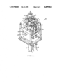
- FIG. 1 is a general perspective view of a subsea well head with a production tree installation including an embodiment of the invention.
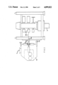
- FIG. 2 is a cross-sectional view of a well head installation similar to that shown in FIG. 1, also showing a remote vehicle.
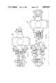
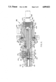
- FIG. 3 is a sectional view of a control device and receptacle, showing a receptacle and control device engaged.
- FIG. 4 is a cross-sectional view similar to that of FIG. 3, with the receptacle and control device disengaged.
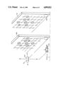
- FIG. 5 is an enlarged perspective view of a manifold, and a corresponding template.
- FIG. 6 is a sectional view, similar to FIG. 3, of a second embodiment of the invention.
- an embodiment of the invention is shown. Unlike the prior art control system in which all the control devices are retained in a single oil filled pod, the embodiment of the invention shown includes a control panel or manifold in which individual control devices may be independently engaged and disengaged.
- FIG. 1 a satellite well head installation, generally designated 10, is shown.
- the well head installation is connected to a well head 12.
- oil may be allowed to flow from the well head 12 through the tree 10 and via subsea pipelines 14, 16 to a central drilling rig (not shown).
- the valve arrangement of the well head installation 10 is of standard form and includes a production ring valve 18, an annulus wing valve 20 (for controlling flow out of pipelines 14, 16), a bypass valve 22 connecting the two pipelines 14, 16 and five other valves, namely a annulus swab valve 24, an annulus master valve 26, a production swab valve 28, a production upper master valve 30 and a production lower master valve 32.
- each main valve is controlled by a respective control element, (eg a pilot valve or hydraulic actuator) which is housed in a control device 80 connected to the main valve via a receptacle 50 and a hydraulic connection line.
- a control element eg a pilot valve or hydraulic actuator
- the connection line, control device and receptacle for the production swab valve 28 are labelled as 28a, 80a, 50a by way of example, in FIG. 2.
- All the receptacles 50 are connected to openings 45 in a panel 40 in a predetermined pattern as shown in FIGS. 1 and 5.
- the panel also includes a further opening (or openings) 220 for receiving an indexing pin (or a plurality of indexing pins) 210 of a Remote Operator Vehicle (R.O.V.) 105.
- R.O.V. Remote Operator Vehicle
- a said receptacle 50, and corresponding control device 80 including the control element are shown in engaged and disengaged positions.
- the receptacle 50 includes a hollow frusto-conical opening 52, a first hollow cylindrical portion 54, and a second hollow cylindrical portion 56 of smaller diameter than the first portion 54.
- the first cylindrical portion 54 is provided, by way of example, with three openings 58, 60, 62 which are connected to hydraulic control lines 64, 66, 68. In practice, more openings may be employed.
- the openings 58-60-62 may be covered, when the control device 80 is not engaged with the receptacle 50, by a displaceable sleeve 69.
- the protective sliding sleeve 69 is formed from oil or grease filled non-corrosive material e.g. NYLON 66 and may be biased into the position shown in FIG. 4 by, for example, a spring (not shown) or other mechanical means.
- the second cylindrical portion 56 is provided with first and second electrical contacts 70, 72.
- a second sleeve 74 is slidably disposed in the portion 56 and displaces dielectric oil over the electrical contacts and is biased into the position shown in FIG. 4 by a biasing means, for example a spring (not shown).
- the electrical contacts 70, 72 may be conductive or inductive.
- locking means which, by way of example, may be a radial pin or series of pins (see below) engaging into a circumferential locking groove 76 shown adjacent the open end of the cylindrical portion 54.
- the control device 80 is arranged to engage with the receptacle 50 and includes a second frustro-conical portion 82, third cylindrical portion 84 and fourth cylindrical portion 86 of similar form to corresponding portions 52, 54, 56, so that the control device 80 may be slidably engaged with the receptacle 50.
- the cylindrical portion 84 is provided with three circumferential grooves 88, 90, 92 disposed, when the control device 80 is engaged with the receptacle 50, in alignment with the openings 64-68.
- the grooves may, alternatively, be situated around openings 64-68 in receptacle 50.
- Each circumferential groove 88-92 is connected to an oil passageway 94, 96, 97, which passageways are connected to a control valve (not shown) disposed within the device 80.
- the three circumferential grooves are hydraulically isolated by elastomer seal rings 99.
- the fourth cylindrical portion 86 includes one or more (in this case two) electrical contacts 98, 100 which are arranged to be disposed in electrical contact with the electrical contacts 70, 72 when the device 80 and receptacle 50 are engaged.
- the contact 98, 100 may be formed as conductive or inductive contacts, depending on the choice of contacts 70, 72.
- the contacts 98, 100 are connected to the control valve operating solenoid.
- One or more (in this case two) retractable pins 102, 104 are also provided adjacent one end of the third cylindrical portion 84. These are arranged to engage selectively the circumferential groove 76 of the receptacle 50, so that the device 80 and receptacle 50 may be positively locked together.
- the device 80 further includes a projection 106, having a recess 108.
- the projection 106 is shaped so as to be engagable with a hydraulically operated tool 110 of a Remote Operator Vehicle (R.O.V.) 105 to allow remote positioning of the control device by the R.O.V. 105 at a subsea location as shown in FIG. 4.
- the R.O.V. tool includes a pair of hollow semi-cylindrical jaws 112, 114 each provided with semi-circular projections 116, 118 which are arranged to engage the groove 108 of the device 80.
- the device 80 includes means to determine when the tool 110 is engaged with the projection 106, to retract the engagement pins 102, 104 while the tool 110 is engaged but to allow the pins 102, 104 to project from the third cylindrical projection 84 when the tool 110 is released.
- the engagement projections 102, 104 will be retracted but once the device has been positioned in the receptacle 50, and the R.O.V. tool 110 is released, the projections are allowed to engage the circumferential groove 76, thus locking the receptacle 50 and device 80 together.
- the sleeves 69, 74 are preferably connected to an oil supply cylinder so that, when the sleeves are displaced from the position shown in FIG. 4 to that shown in FIG. 3, a supply of oil is displaced across the connection surfaces to dispel any seawater, through oil ways (not shown).
- control devices 80 In use, the subsea installation would initially be provided with a full complement of control devices 80, one for each main valve shown in FIG. 1.
- the control devices would be of the general form shown in FIGS. 3 and 4, each connected to a respective receptacle 50 in the panel 40.
- Control signals to the valve of a said control device 80 would be passed through the appropriate receptacle 50 via at least one of the hydraulic and/or electrical connections between the receptacle and device, which control signals would be supplied from a central drilling rig or other surface installation via a control umbilical 13, as shown in FIG. 1.
- control valve, of the control device 80 would then respond to such control signals to operate its associated main valve of the installation, in accordance with the control signals received, the control valve sending open/close hydraulic (or electrical) signals via others of the electrical and hydraulic connections between the receptacle and device to the appropriate main valve.
- the receptacles, 50 are disposed in the panel 40 in a predetermined pattern as, for example, shown in more detail in FIG. 5. Once the manifold pattern has been chosen, a template 200 can be made corresponding to the receptacle pattern.
- This may then be used to program accurately the movements of the R.O.V. tool 110 that will be required in order for the R.O.V. to recover the faulty component and replace this with a fully operational substitute.
- a dry run may be effected on the surface completely under computer control, with the necessary movements being stored in the memory of the computer. Then, all that is necessary is for the R.O.V. to be aligned, using its indexing pin or pins 210, with the corresponding opening or openings 220 of the manifold 40 at the subsea installation, the R.O.V. then completing the operation without needing any further assistance from the surface.
- This method of operation has particular advantages in low visibility situations.
- Materials for the apparatus are selected in order for compatability with sea-water environment, evaluation of electrolyses, earth grounding and type of hydraulic control fluid.
- body/bolting Stainless steel
- moving parts Monel/Inconel/Alu bronze
- Electrical contacts gold plated.
- FIG. 6 shows a second embodiment of the invention.
- the control device and receptacle of this embodiment have substantial similarities to those of the embodiment of FIGS. 3 and 4 and similar parts are represented by the same reference numerals, with the addition of 300.
- the major difference between this embodiment and the embodiment of FIGS. 3 and 4 are as follows:
- the seal rings 399 are spaced at different intervals so that, on entry of the device into the receptacle, the seal rings do not all pass the grooves 430, 434 at the same time thus smoothing entry.
- the three circumferential grooves 430, 432, 434 provide, respectively, a pressure return line and two control lines.
- the pressure return line is configured to be closest to the inserted end of the device 380 as this is the hydraulic connection most likely, of the three, to fail, due to the greater abrasion which the adjacent seals may suffer when the control device 380 is inserted in the receptacle 350.
- Two electrical contacts 370, 372 are provided on the receptacle 350 and these are connected to the control umbilical via an electrical connector 373.
- Respective self activated slip rings 440, 442 are provided on the control device 380. These slip rings are radially resilient so as to be forced into biased contact with the contacts 370, 372 when the device 380 is engaged with receptacle 350. Contact is preferably enhanced by means of an annular ring of resilient material, for example synthetic plastics 444 formed between the free ends for the slip rings 440, 442. Electrical connections from the slip rings run internally of the device 380 through conduit 446 and emerge through opening 448 for external connection, via a sheathed cable, to an actuating solenoid in the housing 450.
- the sleeve 374 unlike the embodiments of FIGS. 3 and 4, is not biased into the covered position but is simply slidable between an ⁇ open ⁇ position, shown in FIG. 6, and a covered position in which the sleeve covers the contacts 370, 372.
- the control device 380 is provided with a resilient, radially deformable tip 447 which has a lip 448 for engagement with a corresponding lip 450 formed on the sleeve 374.
- the sleeve 374 further includes radial projections 451, 452 separated by an axial slot, which cooperate, in the open and covered positions respectively with a stop 454 provided on the receptacle 350.
- the tip 447 forces the sleeve 374 axially to the position shown in FIG. 6.
- the radial projection 451 abuts against the stop 354 which allows the tip 447 to snap into engagement with the sleeve 374, the lips 448, 450 cooperating.
- the tip 447 pulls the sleeve 374 axially until the projection 452 abuts against stop 454 at which time the resilient tip 447 disengages from the sleeve 374, leaving the sleeve in the covered position.
- a spring loaded detent device for example a captive spring biased ball bearing, is preferably located at the tip of the projection 452, the ball bearing being arranged to engage a hollow formed in the sleeve 374 adjacent projection 452, to provide retention of the sleeve 374 in the covered position, but allow release when forced by insertion of the device 380.
- the locking mechanism comprises two pins 404 which engage with a circumferential groove 376.
- the pins 404 have a semi-spherical tip, with the groove having a cooperating trapezoidal cross section.
- Each pin 404 is biased inwardly by means of a respective spring 460 and is held in the outward position, as shown in FIG. 6, by a respective axially movable piston 462.
- Each piston is connected to a respective actuating pin 464 via a retention spring 466 which holds the piston 462 in the locked position shown in FIG. 6.
- the pins 464 are engaged by an annular piston connected to the operating tool of the ROV.
- control device comprises a control valve in the examples, any control element, for example a hydraulic actuator, may be used.
Abstract
Description
Claims (15)
Applications Claiming Priority (2)
| Application Number | Priority Date | Filing Date | Title |
|---|---|---|---|
| GB8720777 | 1987-09-04 | ||
| GB8720777A GB2209361A (en) | 1987-09-04 | 1987-09-04 | Controlling underwater installations |
Publications (1)
| Publication Number | Publication Date |
|---|---|
| US4899822A true US4899822A (en) | 1990-02-13 |
Family
ID=10623245
Family Applications (1)
| Application Number | Title | Priority Date | Filing Date |
|---|---|---|---|
| US07/240,058 Expired - Fee Related US4899822A (en) | 1987-09-04 | 1988-09-02 | Apparatus for controlling the operation of an underwater installation |
Country Status (3)
| Country | Link |
|---|---|
| US (1) | US4899822A (en) |
| GB (1) | GB2209361A (en) |
| NO (1) | NO883941L (en) |
Cited By (27)
| Publication number | Priority date | Publication date | Assignee | Title |
|---|---|---|---|---|
| US5088558A (en) * | 1989-02-24 | 1992-02-18 | Frank Mohn | Undersea package and installation system |
| US5163782A (en) * | 1990-10-12 | 1992-11-17 | Petroleo Brasileiro S.A. - Petrobras | Subsea connection system and active connector utilized in said system |
| US5181798A (en) * | 1991-09-13 | 1993-01-26 | Shell Oil Company | Double pipe turntable and stinger |
| EP0527619A1 (en) * | 1991-08-09 | 1993-02-17 | Petroleo Brasileiro S.A. - Petrobras | Wet christmas tree |
| US5209673A (en) * | 1989-01-18 | 1993-05-11 | Framo Developments (Uk) Limited | Subsea electrical conductive insert coupling |
| US5398761A (en) * | 1993-05-03 | 1995-03-21 | Syntron, Inc. | Subsea blowout preventer modular control pod |
| US6059039A (en) * | 1997-11-12 | 2000-05-09 | Exxonmobil Upstream Research Company | Extendable semi-clustered subsea development system |
| WO2000026998A1 (en) * | 1998-10-30 | 2000-05-11 | Expro North Sea Limited | Electrical connector system |
| US6098715A (en) * | 1997-07-30 | 2000-08-08 | Abb Vetco Gray Inc. | Flowline connection system |
| US6460621B2 (en) | 1999-12-10 | 2002-10-08 | Abb Vetco Gray Inc. | Light-intervention subsea tree system |
| US6644410B1 (en) | 2000-07-27 | 2003-11-11 | Christopher John Lindsey-Curran | Modular subsea control system |
| US20040198086A1 (en) * | 2003-04-01 | 2004-10-07 | Festo Ag & Co. | Control device |
| US20040216884A1 (en) * | 2003-05-01 | 2004-11-04 | Cooper Cameron Corporation | Subsea choke control system |
| US20060096645A1 (en) * | 2004-11-09 | 2006-05-11 | Morten Halvorsen | System for direct electrically operated hydraulic control valve |
| US20060231264A1 (en) * | 2005-03-11 | 2006-10-19 | Boyce Charles B | Riserless modular subsea well intervention, method and apparatus |
| US20060237194A1 (en) * | 2003-05-31 | 2006-10-26 | Des Enhanced Recovery Limited | Apparatus and method for recovering fluids from a well and/or injecting fluids into a well |
| US20080199257A1 (en) * | 2003-11-13 | 2008-08-21 | Aker Kvaernersubsea As | Vertical Installation of an Elongated Process Unit |
| US20080202760A1 (en) * | 2007-02-24 | 2008-08-28 | M.S.C.M. Limited | Subsea securing devices |
| US20090025936A1 (en) * | 2004-02-26 | 2009-01-29 | Des Enhanced Recovery Limited | Connection system for subsea flow interface equipment |
| US20090266542A1 (en) * | 2006-09-13 | 2009-10-29 | Cameron International Corporation | Capillary injector |
| US20100044038A1 (en) * | 2006-12-18 | 2010-02-25 | Cameron International Corporation | Apparatus and method for processing fluids from a well |
| US20100101799A1 (en) * | 2008-10-27 | 2010-04-29 | Vetco Gray Inc. | System, method and apparatus for a modular production tree assembly to reduce weight during transfer of tree to rig |
| US20100206545A1 (en) * | 2007-07-25 | 2010-08-19 | Cameron International Corporation | System and method to seal multiple control lines |
| US20120175124A1 (en) * | 2010-12-29 | 2012-07-12 | M.S.C.M. Limited | Stab plates and subsea connection equipment |
| US8297360B2 (en) | 2006-12-18 | 2012-10-30 | Cameron International Corporation | Apparatus and method for processing fluids from a well |
| US20130252461A1 (en) * | 2012-03-23 | 2013-09-26 | Erbe Elektromedizin Gmbh | Plug and Socket Connector Part For a Medical Device or Instrument |
| CN105048175A (en) * | 2015-06-28 | 2015-11-11 | 中航光电科技股份有限公司 | Connector assembly |
Families Citing this family (4)
| Publication number | Priority date | Publication date | Assignee | Title |
|---|---|---|---|---|
| NO169059C (en) * | 1990-03-19 | 1992-05-06 | Holta Leif | TOOL USE DEVICE FOR REPLACEMENT OF AN INSTRUMENTS IN THEIR FUNCTIONAL POSITION ARE ENTERED BY AN INSTRUMENT HOUSE WHICH MAY BE CONNECTED IN A FLUID CONTROL, USE AND PROCEDURE FOR REPLACING THE INSTRUMENTS |
| FR2688049B1 (en) * | 1992-03-02 | 1994-04-29 | Eca | ARRANGEMENT FOR THE REMOTE CONTROL OF THE OPERATION OF A HYDRAULICALLY ACTUATED VALVE AND OIL SINK HEAD. |
| GB9324229D0 (en) * | 1993-11-25 | 1994-01-12 | Subsea Offshore Ltd | A control mechanism |
| NO324407B1 (en) * | 2006-01-24 | 2007-10-08 | Ifokus Engineering As | Device at coupling door for use under water |
Citations (25)
| Publication number | Priority date | Publication date | Assignee | Title |
|---|---|---|---|---|
| US3339632A (en) * | 1964-01-21 | 1967-09-05 | Hydril Co | Underwater connector |
| US3486556A (en) * | 1967-05-01 | 1969-12-30 | Stewart & Stevenson Inc Jim | Underwater connecting apparatus |
| US3633667A (en) * | 1969-12-08 | 1972-01-11 | Deep Oil Technology Inc | Subsea wellhead system |
| US3839608A (en) * | 1973-07-23 | 1974-10-01 | Stewart & Stevenson Inc Jim | Apparatus for making and breaking an electrical underwater connection between releasable underwater members |
| GB1472229A (en) * | 1973-08-17 | 1977-05-04 | Putnam P | Subsea well-head installations |
| US4080025A (en) * | 1976-05-03 | 1978-03-21 | Matra | Automatic connector for underwater connection |
| US4117287A (en) * | 1977-04-11 | 1978-09-26 | Compagnie Francaise Des Petroles | Combined electrical-hydraulic connector means |
| GB1555719A (en) * | 1978-02-06 | 1979-11-14 | British Petroleum Co | Electrical and hydraulic connector |
| GB1576897A (en) * | 1976-11-22 | 1980-10-15 | Elf Aquitaine | Subsea installation |
| GB2059483A (en) * | 1979-10-02 | 1981-04-23 | Fmc Corp | Method and apparatus for controlling subsea well template production systems |
| US4411454A (en) * | 1980-11-03 | 1983-10-25 | Nl Industries, Inc. | Underwater wellhead connector |
| US4444218A (en) * | 1980-10-30 | 1984-04-24 | Koomey, Inc. | Underwater fluid connector |
| US4494602A (en) * | 1982-01-14 | 1985-01-22 | Societe Nationale Elf Aquitaine (Production) | Electrical connection device for an underwater well head |
| US4525918A (en) * | 1982-04-16 | 1985-07-02 | Messerschmitt-Boelkow-Blohm Gesellschaft Mit Beschraenkter Haftung | Two component tool holder, especially for a machine tool or robot |
| GB2152565A (en) * | 1983-11-21 | 1985-08-07 | Elf Aquitaine | An oil production installation for a sub-sea station of modular design |
| GB2152556A (en) * | 1983-11-21 | 1985-08-07 | Elf Aquitaine | A device for positioning, activating and connecting modules of a sub-sea oil production station |
| WO1986000353A1 (en) * | 1984-06-22 | 1986-01-16 | Total Transportation Systems (International) A/S | Underwater operating system |
| WO1986001852A1 (en) * | 1984-09-12 | 1986-03-27 | Britoil Plc | Underwater well equipment |
| GB2167469A (en) * | 1984-11-01 | 1986-05-29 | Vetco Offshore Ind Inc | Tree control manifold |
| GB2174442A (en) * | 1985-05-04 | 1986-11-05 | British Petroleum Co Plc | Subsea oil production system |
| US4661017A (en) * | 1985-03-29 | 1987-04-28 | Exxon Production Research Co. | Method and apparatus for aligning underwater components |
| US4682913A (en) * | 1986-08-28 | 1987-07-28 | Shell Offshore Inc. | Hydraulic stab connector |
| GB2194980A (en) * | 1986-07-26 | 1988-03-23 | British Petroleum Co Plc | Control system for subsea oil production |
| WO1988003596A1 (en) * | 1986-11-11 | 1988-05-19 | Myrmidon Subsea Controls Ltd | Subsea systems and devices |
| US4770248A (en) * | 1987-01-08 | 1988-09-13 | Hughes Tool Company | Device to orient electrical connectors in a subsea well |
-
1987
- 1987-09-04 GB GB8720777A patent/GB2209361A/en not_active Withdrawn
-
1988
- 1988-09-02 NO NO88883941A patent/NO883941L/en unknown
- 1988-09-02 US US07/240,058 patent/US4899822A/en not_active Expired - Fee Related
Patent Citations (26)
| Publication number | Priority date | Publication date | Assignee | Title |
|---|---|---|---|---|
| US3339632A (en) * | 1964-01-21 | 1967-09-05 | Hydril Co | Underwater connector |
| US3486556A (en) * | 1967-05-01 | 1969-12-30 | Stewart & Stevenson Inc Jim | Underwater connecting apparatus |
| US3633667A (en) * | 1969-12-08 | 1972-01-11 | Deep Oil Technology Inc | Subsea wellhead system |
| US3839608A (en) * | 1973-07-23 | 1974-10-01 | Stewart & Stevenson Inc Jim | Apparatus for making and breaking an electrical underwater connection between releasable underwater members |
| GB1472229A (en) * | 1973-08-17 | 1977-05-04 | Putnam P | Subsea well-head installations |
| US4080025A (en) * | 1976-05-03 | 1978-03-21 | Matra | Automatic connector for underwater connection |
| GB1576897A (en) * | 1976-11-22 | 1980-10-15 | Elf Aquitaine | Subsea installation |
| US4117287A (en) * | 1977-04-11 | 1978-09-26 | Compagnie Francaise Des Petroles | Combined electrical-hydraulic connector means |
| GB1555719A (en) * | 1978-02-06 | 1979-11-14 | British Petroleum Co | Electrical and hydraulic connector |
| GB2059483A (en) * | 1979-10-02 | 1981-04-23 | Fmc Corp | Method and apparatus for controlling subsea well template production systems |
| US4444218A (en) * | 1980-10-30 | 1984-04-24 | Koomey, Inc. | Underwater fluid connector |
| GB2137677A (en) * | 1980-11-03 | 1984-10-10 | Nl Industries Inc | Underwater wellhead connector |
| US4411454A (en) * | 1980-11-03 | 1983-10-25 | Nl Industries, Inc. | Underwater wellhead connector |
| US4494602A (en) * | 1982-01-14 | 1985-01-22 | Societe Nationale Elf Aquitaine (Production) | Electrical connection device for an underwater well head |
| US4525918A (en) * | 1982-04-16 | 1985-07-02 | Messerschmitt-Boelkow-Blohm Gesellschaft Mit Beschraenkter Haftung | Two component tool holder, especially for a machine tool or robot |
| GB2152565A (en) * | 1983-11-21 | 1985-08-07 | Elf Aquitaine | An oil production installation for a sub-sea station of modular design |
| GB2152556A (en) * | 1983-11-21 | 1985-08-07 | Elf Aquitaine | A device for positioning, activating and connecting modules of a sub-sea oil production station |
| WO1986000353A1 (en) * | 1984-06-22 | 1986-01-16 | Total Transportation Systems (International) A/S | Underwater operating system |
| WO1986001852A1 (en) * | 1984-09-12 | 1986-03-27 | Britoil Plc | Underwater well equipment |
| GB2167469A (en) * | 1984-11-01 | 1986-05-29 | Vetco Offshore Ind Inc | Tree control manifold |
| US4661017A (en) * | 1985-03-29 | 1987-04-28 | Exxon Production Research Co. | Method and apparatus for aligning underwater components |
| GB2174442A (en) * | 1985-05-04 | 1986-11-05 | British Petroleum Co Plc | Subsea oil production system |
| GB2194980A (en) * | 1986-07-26 | 1988-03-23 | British Petroleum Co Plc | Control system for subsea oil production |
| US4682913A (en) * | 1986-08-28 | 1987-07-28 | Shell Offshore Inc. | Hydraulic stab connector |
| WO1988003596A1 (en) * | 1986-11-11 | 1988-05-19 | Myrmidon Subsea Controls Ltd | Subsea systems and devices |
| US4770248A (en) * | 1987-01-08 | 1988-09-13 | Hughes Tool Company | Device to orient electrical connectors in a subsea well |
Cited By (67)
| Publication number | Priority date | Publication date | Assignee | Title |
|---|---|---|---|---|
| US5209673A (en) * | 1989-01-18 | 1993-05-11 | Framo Developments (Uk) Limited | Subsea electrical conductive insert coupling |
| US5088558A (en) * | 1989-02-24 | 1992-02-18 | Frank Mohn | Undersea package and installation system |
| US5163782A (en) * | 1990-10-12 | 1992-11-17 | Petroleo Brasileiro S.A. - Petrobras | Subsea connection system and active connector utilized in said system |
| EP0527619A1 (en) * | 1991-08-09 | 1993-02-17 | Petroleo Brasileiro S.A. - Petrobras | Wet christmas tree |
| AU655048B2 (en) * | 1991-08-09 | 1994-12-01 | Petroleo Brasileiro S.A. - Petrobras | Wet Christmas tree |
| US5181798A (en) * | 1991-09-13 | 1993-01-26 | Shell Oil Company | Double pipe turntable and stinger |
| US5398761A (en) * | 1993-05-03 | 1995-03-21 | Syntron, Inc. | Subsea blowout preventer modular control pod |
| US6098715A (en) * | 1997-07-30 | 2000-08-08 | Abb Vetco Gray Inc. | Flowline connection system |
| US6059039A (en) * | 1997-11-12 | 2000-05-09 | Exxonmobil Upstream Research Company | Extendable semi-clustered subsea development system |
| WO2000026998A1 (en) * | 1998-10-30 | 2000-05-11 | Expro North Sea Limited | Electrical connector system |
| US6698520B2 (en) | 1999-12-10 | 2004-03-02 | Abb Vetco Gray Inc. | Light-intervention subsea tree system |
| US6460621B2 (en) | 1999-12-10 | 2002-10-08 | Abb Vetco Gray Inc. | Light-intervention subsea tree system |
| US6644410B1 (en) | 2000-07-27 | 2003-11-11 | Christopher John Lindsey-Curran | Modular subsea control system |
| US8733436B2 (en) | 2002-07-16 | 2014-05-27 | Cameron Systems (Ireland) Limited | Apparatus and method for recovering fluids from a well and/or injecting fluids into a well |
| US10107069B2 (en) | 2002-07-16 | 2018-10-23 | Onesubsea Ip Uk Limited | Apparatus and method for recovering fluids from a well and/or injecting fluids into a well |
| US9556710B2 (en) | 2002-07-16 | 2017-01-31 | Onesubsea Ip Uk Limited | Apparatus and method for recovering fluids from a well and/or injecting fluids into a well |
| US8746332B2 (en) | 2002-07-16 | 2014-06-10 | Cameron Systems (Ireland) Limited | Apparatus and method for recovering fluids from a well and/or injecting fluids into a well |
| US8469086B2 (en) | 2002-07-16 | 2013-06-25 | Cameron Systems (Ireland) Limited | Apparatus and method for recovering fluids from a well and/or injecting fluids into a well |
| US8167049B2 (en) | 2002-07-16 | 2012-05-01 | Cameron Systems (Ireland) Limited | Apparatus and method for recovering fluids from a well and/or injecting fluids into a well |
| US20110226483A1 (en) * | 2002-07-16 | 2011-09-22 | Cameron International Corporation | Apparatus and method for recovering fluids from a well and/or injecting fluids into a well |
| US6916192B2 (en) * | 2003-04-01 | 2005-07-12 | Festo Ag & Co. | Control device |
| US20040198086A1 (en) * | 2003-04-01 | 2004-10-07 | Festo Ag & Co. | Control device |
| US20040216884A1 (en) * | 2003-05-01 | 2004-11-04 | Cooper Cameron Corporation | Subsea choke control system |
| US6988554B2 (en) | 2003-05-01 | 2006-01-24 | Cooper Cameron Corporation | Subsea choke control system |
| US7992643B2 (en) | 2003-05-31 | 2011-08-09 | Cameron Systems (Ireland) Limited | Apparatus and method for recovering fluids from a well and/or injecting fluids into a well |
| US20060237194A1 (en) * | 2003-05-31 | 2006-10-26 | Des Enhanced Recovery Limited | Apparatus and method for recovering fluids from a well and/or injecting fluids into a well |
| US20090301728A1 (en) * | 2003-05-31 | 2009-12-10 | Cameron International Corporation | Apparatus and method for recovering fluids from a well and/or injecting fluids into a well |
| US8622138B2 (en) | 2003-05-31 | 2014-01-07 | Cameron Systems (Ireland) Limited | Apparatus and method for recovering fluids from a well and/or injecting fluids into a well |
| US8573306B2 (en) | 2003-05-31 | 2013-11-05 | Cameron Systems (Ireland) Limited | Apparatus and method for recovering fluids from a well and/or injecting fluids into a well |
| US20100206547A1 (en) * | 2003-05-31 | 2010-08-19 | Cameron International Corporation | Apparatus and Method for Recovering Fluids From a Well and/or Injecting Fluids Into a Well |
| US20100206576A1 (en) * | 2003-05-31 | 2010-08-19 | Cameron International Corporation | Apparatus and Method for Recovering Fluids From a Well and/or Injecting Fluids Into a Well |
| US8540018B2 (en) | 2003-05-31 | 2013-09-24 | Cameron Systems (Ireland) Limited | Apparatus and method for recovering fluids from a well and/or injecting fluids into a well |
| US7992633B2 (en) | 2003-05-31 | 2011-08-09 | Cameron Systems (Ireland) Limited | Apparatus and method for recovering fluids from a well and/or injecting fluids into a well |
| US20090294125A1 (en) * | 2003-05-31 | 2009-12-03 | Cameron International Corporation | Apparatus and method for recovering fluids from a well and/or injecting fluids into a well |
| US8281864B2 (en) | 2003-05-31 | 2012-10-09 | Cameron Systems (Ireland) Limited | Apparatus and method for recovering fluids from a well and/or injecting fluids into a well |
| US8272435B2 (en) | 2003-05-31 | 2012-09-25 | Cameron Systems (Ireland) Limited | Apparatus and method for recovering fluids from a well and/or injecting fluids into a well |
| US8220535B2 (en) | 2003-05-31 | 2012-07-17 | Cameron Systems (Ireland) Limited | Apparatus and method for recovering fluids from a well and/or injecting fluids into a well |
| US8066067B2 (en) | 2003-05-31 | 2011-11-29 | Cameron International Corporation | Apparatus and method for recovering fluids from a well and/or injecting fluids into a well |
| US8122948B2 (en) | 2003-05-31 | 2012-02-28 | Cameron Systems (Ireland) Limited | Apparatus and method for recovering fluids from a well and/or injecting fluids into a well |
| US8091630B2 (en) | 2003-05-31 | 2012-01-10 | Cameron Systems (Ireland) Limited | Apparatus and method for recovering fluids from a well and/or injecting fluids into a well |
| US20080199257A1 (en) * | 2003-11-13 | 2008-08-21 | Aker Kvaernersubsea As | Vertical Installation of an Elongated Process Unit |
| US20090025936A1 (en) * | 2004-02-26 | 2009-01-29 | Des Enhanced Recovery Limited | Connection system for subsea flow interface equipment |
| US8066076B2 (en) | 2004-02-26 | 2011-11-29 | Cameron Systems (Ireland) Limited | Connection system for subsea flow interface equipment |
| US8776891B2 (en) | 2004-02-26 | 2014-07-15 | Cameron Systems (Ireland) Limited | Connection system for subsea flow interface equipment |
| US9260944B2 (en) | 2004-02-26 | 2016-02-16 | Onesubsea Ip Uk Limited | Connection system for subsea flow interface equipment |
| US20060096645A1 (en) * | 2004-11-09 | 2006-05-11 | Morten Halvorsen | System for direct electrically operated hydraulic control valve |
| US7891429B2 (en) * | 2005-03-11 | 2011-02-22 | Saipem America Inc. | Riserless modular subsea well intervention, method and apparatus |
| US20060231264A1 (en) * | 2005-03-11 | 2006-10-19 | Boyce Charles B | Riserless modular subsea well intervention, method and apparatus |
| US8066063B2 (en) | 2006-09-13 | 2011-11-29 | Cameron International Corporation | Capillary injector |
| US20090266542A1 (en) * | 2006-09-13 | 2009-10-29 | Cameron International Corporation | Capillary injector |
| US8297360B2 (en) | 2006-12-18 | 2012-10-30 | Cameron International Corporation | Apparatus and method for processing fluids from a well |
| US9291021B2 (en) | 2006-12-18 | 2016-03-22 | Onesubsea Ip Uk Limited | Apparatus and method for processing fluids from a well |
| US8104541B2 (en) | 2006-12-18 | 2012-01-31 | Cameron International Corporation | Apparatus and method for processing fluids from a well |
| US20100044038A1 (en) * | 2006-12-18 | 2010-02-25 | Cameron International Corporation | Apparatus and method for processing fluids from a well |
| US8776893B2 (en) | 2006-12-18 | 2014-07-15 | Cameron International Corporation | Apparatus and method for processing fluids from a well |
| US20080202760A1 (en) * | 2007-02-24 | 2008-08-28 | M.S.C.M. Limited | Subsea securing devices |
| US8011434B2 (en) * | 2007-02-24 | 2011-09-06 | M.S.C.M. Limited | Subsea securing devices |
| US20100206545A1 (en) * | 2007-07-25 | 2010-08-19 | Cameron International Corporation | System and method to seal multiple control lines |
| US9803445B2 (en) | 2007-07-25 | 2017-10-31 | Cameron International Corporation | System and method to seal multiple control lines |
| US10526859B2 (en) | 2007-07-25 | 2020-01-07 | Cameron International Corporation | System and method to seal multiple control lines |
| US20100101799A1 (en) * | 2008-10-27 | 2010-04-29 | Vetco Gray Inc. | System, method and apparatus for a modular production tree assembly to reduce weight during transfer of tree to rig |
| US8151890B2 (en) * | 2008-10-27 | 2012-04-10 | Vetco Gray Inc. | System, method and apparatus for a modular production tree assembly to reduce weight during transfer of tree to rig |
| US9016380B2 (en) * | 2010-12-29 | 2015-04-28 | M.S.C.M. Limited | Stab plates and subsea connection equipment |
| US20120175124A1 (en) * | 2010-12-29 | 2012-07-12 | M.S.C.M. Limited | Stab plates and subsea connection equipment |
| US20130252461A1 (en) * | 2012-03-23 | 2013-09-26 | Erbe Elektromedizin Gmbh | Plug and Socket Connector Part For a Medical Device or Instrument |
| CN105048175A (en) * | 2015-06-28 | 2015-11-11 | 中航光电科技股份有限公司 | Connector assembly |
| CN105048175B (en) * | 2015-06-28 | 2017-09-22 | 中航光电科技股份有限公司 | A kind of connector assembly |
Also Published As
| Publication number | Publication date |
|---|---|
| GB2209361A (en) | 1989-05-10 |
| NO883941L (en) | 1989-03-06 |
| NO883941D0 (en) | 1988-09-02 |
| GB8720777D0 (en) | 1987-10-14 |
Similar Documents
| Publication | Publication Date | Title |
|---|---|---|
| US4899822A (en) | Apparatus for controlling the operation of an underwater installation | |
| US5771974A (en) | Test tree closure device for a cased subsea oil well | |
| US4607701A (en) | Tree control manifold | |
| US4109712A (en) | Safety apparatus for automatically sealing hydraulic lines within a sub-sea well casing | |
| US4863314A (en) | Hydraulic stab connector, frictionless | |
| US6516887B2 (en) | Method and apparatus for tensioning tubular members | |
| US7216714B2 (en) | Modular, distributed, ROV retrievable subsea control system, associated deepwater subsea blowout preventer stack configuration, and methods of use | |
| US5706893A (en) | Tubing hanger | |
| CA1250226A (en) | Subsea flowline connector | |
| US3241864A (en) | Automatic connector | |
| US20020009336A1 (en) | Connection system for catenary riser | |
| GB2163197A (en) | Tubing suspension system | |
| US4432670A (en) | Combination connector and flex joint for underwater tension elements | |
| US20140048274A1 (en) | Modular, Distributed, ROV Retrievable Subsea Control System, Associated Deepwater Subsea Blowout Preventer Stack Configuration, and Methods of Use | |
| US3646996A (en) | Well tools | |
| US3536344A (en) | Subsea valve and valve operator assembly | |
| GB2209550A (en) | Controlling underwater installations | |
| US5941574A (en) | Horizontal penetrator with multiple metal sealing pressure lines | |
| US7350580B1 (en) | Subsea pass thru switching system | |
| US3251611A (en) | Wellhead connector | |
| US4699215A (en) | External tie-back connector | |
| US4825948A (en) | Remotely variable multiple bore ram system and method | |
| EP0235365A2 (en) | Subsea electrical connector and method | |
| EP3559399B1 (en) | Fluid control system | |
| US11614190B2 (en) | Secondary unlock tool for subsea connectors |
Legal Events
| Date | Code | Title | Description |
|---|---|---|---|
| AS | Assignment |
Owner name: AUTOCON LIMITED, GREAT BRITAIN Free format text: ASSIGNMENT OF ASSIGNORS INTEREST.;ASSIGNORS:DAESCHLER, JEAN-LOUIS;ASBURY, ANTHONY J.;REEL/FRAME:005001/0329;SIGNING DATES FROM 19881014 TO 19881019 |
|
| AS | Assignment |
Owner name: CAMCO INC., TEXAS Free format text: ASSIGNMENT OF ASSIGNORS INTEREST.;ASSIGNOR:AUTOCON LIMITED;REEL/FRAME:005184/0334 Effective date: 19891010 |
|
| REMI | Maintenance fee reminder mailed | ||
| LAPS | Lapse for failure to pay maintenance fees | ||
| FP | Lapsed due to failure to pay maintenance fee |
Effective date: 19940213 |
|
| STCH | Information on status: patent discontinuation |
Free format text: PATENT EXPIRED DUE TO NONPAYMENT OF MAINTENANCE FEES UNDER 37 CFR 1.362 |