US4899823A - Method and apparatus for running coiled tubing in subsea wells - Google Patents
Method and apparatus for running coiled tubing in subsea wells Download PDFInfo
- Publication number
- US4899823A US4899823A US07/287,039 US28703988A US4899823A US 4899823 A US4899823 A US 4899823A US 28703988 A US28703988 A US 28703988A US 4899823 A US4899823 A US 4899823A
- Authority
- US
- United States
- Prior art keywords
- tubing
- injector
- enclosure
- well
- wellhead
- Prior art date
- Legal status (The legal status is an assumption and is not a legal conclusion. Google has not performed a legal analysis and makes no representation as to the accuracy of the status listed.)
- Expired - Lifetime
Links
Images
Classifications
-
- E—FIXED CONSTRUCTIONS
- E21—EARTH DRILLING; MINING
- E21B—EARTH DRILLING, e.g. DEEP DRILLING; OBTAINING OIL, GAS, WATER, SOLUBLE OR MELTABLE MATERIALS OR A SLURRY OF MINERALS FROM WELLS
- E21B29/00—Cutting or destroying pipes, packers, plugs, or wire lines, located in boreholes or wells, e.g. cutting of damaged pipes, of windows; Deforming of pipes in boreholes or wells; Reconditioning of well casings while in the ground
- E21B29/12—Cutting or destroying pipes, packers, plugs, or wire lines, located in boreholes or wells, e.g. cutting of damaged pipes, of windows; Deforming of pipes in boreholes or wells; Reconditioning of well casings while in the ground specially adapted for underwater installations
-
- E—FIXED CONSTRUCTIONS
- E21—EARTH DRILLING; MINING
- E21B—EARTH DRILLING, e.g. DEEP DRILLING; OBTAINING OIL, GAS, WATER, SOLUBLE OR MELTABLE MATERIALS OR A SLURRY OF MINERALS FROM WELLS
- E21B19/00—Handling rods, casings, tubes or the like outside the borehole, e.g. in the derrick; Apparatus for feeding the rods or cables
- E21B19/22—Handling reeled pipe or rod units, e.g. flexible drilling pipes
-
- E—FIXED CONSTRUCTIONS
- E21—EARTH DRILLING; MINING
- E21B—EARTH DRILLING, e.g. DEEP DRILLING; OBTAINING OIL, GAS, WATER, SOLUBLE OR MELTABLE MATERIALS OR A SLURRY OF MINERALS FROM WELLS
- E21B33/00—Sealing or packing boreholes or wells
- E21B33/02—Surface sealing or packing
- E21B33/03—Well heads; Setting-up thereof
- E21B33/068—Well heads; Setting-up thereof having provision for introducing objects or fluids into, or removing objects from, wells
- E21B33/076—Well heads; Setting-up thereof having provision for introducing objects or fluids into, or removing objects from, wells specially adapted for underwater installations
Definitions
- This invention relates to method and apparatus for running coiled tubing in subsea wells whose wellheads are located on or near the ocean floor. Production lines from such wells usually extend along the ocean floor.
- An object of this invention is to provide a simple, relatively inexpensive apparatus and method of using coiled tubing in subsea wells.
- Another object is to provide for using coiled tubing in subsea wells in which the tubing injector is positioned on the subsea wellhead.
- Another object is to provide for using coiled tubing in subsea wells in which the tubing injector and tubing are run simultaneously, with the tubing latched in the tubing injector, and the tubing injector landed on and latched to the wellhead.
- Another object is to provide for using coiled tubing in subsea wells as in the preceding object in which a tubing shear is provided on top of the tubing injector to provide for emergency release of the tubing from the tubing injector.
- Another object is to provide for using coiled tubing in subsea wells in which the tubing injector and a tubing carrying a well tool are simultaneously run with the tubing latched in the tubing injector and the tubing injector landed on and latched to the wellhead.
- Another object is to provide for using coiled tubing in subsea wells as in the preceding objects in which a well fluid stuffing box is carried by the tubing injector with the tubing in the stuffing box during running.
- Another object is to provide for using coiled tubing in subsea wells in which the tubing and tubing injector are run simultaneously, with the tubing latched in the tubing injector, and the weight of the tubing injector is used to unreel the coiled tubing.
- Another object is to provide for using coiled tubing in subsea wells in which during retrieval of the tubing it is latched to the tubing injector and the weight of the injector is used to maintain the tubing in tension during the retrieval operation.
- Another object is to provide a subsea tubing injector within an enclosure to prevent sea water from contacting the tubing injector in which provision is made to maintain the enclosure under pressure approximating external pressure.
- Another object is to provide a subsea tubing injector with an open bottom bell type enclosure or a fluid tight enclosure and to maintain a selected fluid in the enclosure under pressure.
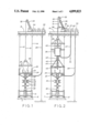
- FIG. 1 is a schematic illustration of a blowout preventer stack and lower latch assembly being run from a surface vessel and landed on a subsea wellhead;
- FIG. 2 is a view similar to FIG. 1 showing the coiled tubing and tubing injector and associated equipment being run on the wellhead of FIG. 1;
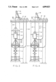
- FIG. 3 is a view similar to FIG. 2 showing the tubing injector landed and latched onto the wellhead;
- FIG. 4 is a view similar to FIG. 3 showing the coiled tubing being used in servicing the well;
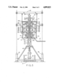
- FIG. 5 is a view partly in elevation and partly in section illustrating a tubing injector and associated equipment for practicing this invention.
- the tubing injector is positioned on the subsea wellhead and injects or retracts tubing as needed.
- the reel on the surface vessel may maintain the tubing in tension and pay out or reel in tubing as needed.
- the tubing injector To position the tubing injector on the wellhead, the tubing is first positioned in the injector and latched in place. Then the injector is lowered through the body of water. The weight of the injector assembly is utilized to pull the tubing from the reel while the reel maintains the tubing in tension by resisting rotation.
- the injector assembly is guided to the wellhead in any desired manner and when landed is latched to the wellhead.
- a blowout preventer stack has previously been landed on the wellhead and the injector assembly is landed on the stack.
- a well fluid stuffing box be carried by the injector and that the tubing extend into and preferably through the box during running of the assembly.
- a tool receiver be provided for the well tool.
- the tubing may be latched in the injector in any desired manner.
- the endless chains of the injector may be locked against movement and held in engagement with the tubing.
- the weight of the injector assembly is utilized to maintain the tubing in tension as it is coiled on the reel.
- the injector be contained within an environmental enclosure.
- This may be a bell type or a fluid tight enclosure.
- a gas such as nitrogen is maintained under pressure in the bell to exclude sea water.
- the gas should be maintained at approximately the same pressure as that exterior of the bell to exclude sea water.
- a barrier fluid such as oil may be maintained in the bottom of the bell to inhibit movement of sea water vapor into the bell.
- a suitable fluid may be maintained in the enclosure, preferably at a pressure approximating exterior pressure to avoid an undesirable differential across the enclosure wall.
- the fluid is maintained at a pressure slightly above the surrounding pressure to insure that sea water cannot invade the enclosure.
- a tubing shear may be provided, preferably on top of the injector.
- a wellhead 10 has guide post 11 & 12 from which guide wires 13 and 14 extend to the surface vessel 15.
- a blowout preventer stack and associated structure is shown landed on the wellhead.
- the structure 16 includes the blowout preventers 17, 18, 19 & 21.
- a lower latch 22 secures the structure to the wellhead.
- Above the stack is the lower section 23 of a latch structure for latching the injector to the wellhead.
- a lower guide frame, indicated generally at 24, is carried on the stack and includes guide post 25 & 26 slidable on guide wires 13 & 14.
- the guide frame includes the connector bulkhead 27 and the lower stack control umbilical 28 which supplies power for any desired equipment such as the several blowout preventers, latches, etc.
- the blowout preventer stack may be considered a part of the wellhead.
- the umbilical 28 is carried on a reel 30 which is operated to control the umbilical as the stack structure is run or retrieved.
- the stack structure 16 is suspended from the lift beam 29 which is in turn suspended by cable 31 which is trained over sheave 32 on arm 33 and wound on reel 34.
- the above described assembly is lowered by paying out cable 31 from reel 34 and then landed on the wellhead 10 and latched in place by latch 22.
- Motion compensation may be provided in any desired manner.
- a coiled tubing injector indicated generally at 35 is suspended from the lift beam and a coiled tubing 36 is introduced into the injector.
- Coiled tubing injectors are well known and an injector such as taught in U.S. Pat. No. 4,655,291 to Cox may be employed.
- the lower pressure beams 74 & 75 shown in U.S. Pat. No. 4,655,291, may be omitted and the chains 28 and 28a shortened if desired as shown in FIG. 5.
- the coiled tubing 36 extends from reel 37 over the sheave structure 38 and then downwardly into the injector.
- the sheave structure 38 is supported on arm 39 by line 41.
- Motion compensation may be provided in any desired manner.
- the tubing 36 is latched in the injector in any desired manner.
- the endless chains of the injector may be locked against movement and held firmly against the tubing to latch the tubing in the injector.
- Other latch structures may be used.
- a well fluid stuffing box 43 be carried by the injector and that prior to lowering the tubing also be positioned in the stuffing box.
- the blowout preventer 42 is positioned below the stuffing box and a tool receiver provided by a spool 44 and/or the upper latch section 46 is carried below the blowout preventer. It is preferred that when a tool is carried by the tubing that the tubing extend through the stuffing box and blowout preventer and that the well tool be positioned in the tool receiver.
- the blow out preventer may be closed to change packing in the stuffing box.
- a tubing shear indicated generally at 45, be included with the injector. As shown the shear is preferably mounted on top of the injector and when operated separates the tubing above the injector.
- the shear 45 is preferably operated by fluid pressure from umbilical 28.
- a suitable upper latch section 46 designed to cooperate with latch section 23 on the blowout preventer stack 16, depends from the spool 44 and when the injector and its associated structure is landed the latch sections 23 and 46 cooperate to latch the injector to the well head through the blowout preventer stack.
- the injector With the injector and associated structure latched to the tubing, the injector is lowered to the wellhead and during lowering the weight of the injector is utilized to unreel tubing from reel 37. Reel 37 is operated to maintain the tubing in tension during the lowering operation. Thus the tubing is maintained under control and any effect of currents is minimized.
- An injector control umbilical 47 is unreeled from reel 48 as the injector is lowered and supplies power to the injector.
- the injector may be operated by hydraulic fluid supplied by umbilical 47.
- the injector may be operated to move tubing through the wellhead.
- the reel 34 will maintain the tubing in tension at all times. Fluid may be injected and any tool on the tubing may be operated in the conventional manner to service the well.
- the lift beam may be released from the injector and retrieved separately.
- the lift beam is again attached to the injector and the latch is released to permit separation of the injector from the blowout preventer stack.
- the cable 31 is taken in to lift the injector and associated equipment.
- the tubing reel 37 is operated to maintain the tubing in tension to insure control of the tubing and proper spooling of the tubing on the reel. Thus the weight of the injector and associated equipment is utilized to maintain the tubing in tension.
- FIG. 5 a form of injector following the teaching of U.S. Pat. No. 4,655,291 is shown.
- any desired form of coiled tubing injector may be employed, reference is made to this patent for a teaching of a suitable injector.
- the injector includes a pair of opposed endless drive chains 48 and 49 driven by motors 51 and 52.
- the chain 48 is trained over drive sprocket 48a and idle sprocket 48b.
- the chain 49 is trained over drive sprocket 49a and idler sprocket 49b.
- These motors may be powered in any desired manner, such as by hydraulic fluid from umbilical 47.
- a pair of opposed endless roller chains 53, 54 hold the drive chains firmly in engagement with the tubing 36.
- These roller chains are carried by pressure beams 55 and 56.
- the pressure beams are supported on yokes 57, 58, 59, and 61 which in turn are carried on rods 62, 63, 64, and 65.
- the injector may be locked to the tubing during running and retrieval of the injector. After the injector is landed, rotation of the drive chains will inject or retrieve pipe from the well.
- the injector is not exposed to sea water.
- the enclosure will include a top 71 and a complete side wall, such as the cylindrical side wall 72 shown.
- pressure fluid preferably nitrogen
- a bottom 73 is provided.
- the enclosure may be filled with a fluid under pressure to equalize pressure with the exterior.
- upper and lower tubing strippers 74 and 75 are provide about the tubing 36 at the top and bottom of the enclosure. With the bell concept the upper stripper is also used.
- strippers leak fluid
- a ported coupling 76 be provided between the stuffing box and stripper 75 to permit disposal of this fluid when utilizing the fluid tight enclosure. With the bell type enclosure the ported coupling is not needed.
- the hydraulic connector bulkhead 77 receives control fluid from the umbilical 28 and distributes it to the various motors as desired through conduits not shown.
- An emergency supply of pressure may be provided by the tank 78.
- the injector is suspended from the bar 29.
- the pressure beams 55 and 56 are positioned to permit the drive chains to receive the tubing and the tubing is positioned between the drive chains.
- the tubing extends down past the blowout preventer and stuffing box. If a tool is to be employed it is position in the tool receiver.
- the pressure beams are positioned to hold the drive chains against the tubing. The drive chains are locked in place.
- the injector may then be lowered from the vessel to the well head while paying out tubing from the reel 37 and while maintaining the tubing in tension.
- the injector may be operated in the conventional manner to move the tubing through the well head, operate tools, etc.
- the injector When it is desired to retrieve the injector, it is first operated to withdraw the tubing from the well head. The latch is then released. With the drive chains locked to the tubing the tubing is reeled on reel 37. The injector is lifted by the lift beam 29 while the reel 37 maintains the tubing in tension to insure proper spooling of the tubing on the reel.
Abstract
Description
Claims (15)
Applications Claiming Priority (2)
| Application Number | Priority Date | Filing Date | Title |
|---|---|---|---|
| GB8821713A GB2222842B (en) | 1988-09-16 | 1988-09-16 | Method and apparatus for running coiled tubing in subsea wells |
| GB8821713 | 1988-09-16 |
Publications (1)
| Publication Number | Publication Date |
|---|---|
| US4899823A true US4899823A (en) | 1990-02-13 |
Family
ID=10643680
Family Applications (1)
| Application Number | Title | Priority Date | Filing Date |
|---|---|---|---|
| US07/287,039 Expired - Lifetime US4899823A (en) | 1988-09-16 | 1988-12-21 | Method and apparatus for running coiled tubing in subsea wells |
Country Status (3)
| Country | Link |
|---|---|
| US (1) | US4899823A (en) |
| BR (1) | BR8806585A (en) |
| GB (2) | GB2222842B (en) |
Cited By (49)
| Publication number | Priority date | Publication date | Assignee | Title |
|---|---|---|---|---|
| US4986360A (en) * | 1989-01-05 | 1991-01-22 | Otis Engineering Corporation | System for handling reeled tubing |
| US5002130A (en) * | 1990-01-29 | 1991-03-26 | Otis Engineering Corp. | System for handling reeled tubing |
| US5163782A (en) * | 1990-10-12 | 1992-11-17 | Petroleo Brasileiro S.A. - Petrobras | Subsea connection system and active connector utilized in said system |
| US5287741A (en) * | 1992-08-31 | 1994-02-22 | Halliburton Company | Methods of perforating and testing wells using coiled tubing |
| US5553668A (en) * | 1995-07-28 | 1996-09-10 | Halliburton Company | Twin carriage tubing injector apparatus |
| WO1996028633A2 (en) * | 1995-03-10 | 1996-09-19 | Baker Hughes Incorporated | Universal pipe injection apparatus for wells and method |
| US5738173A (en) * | 1995-03-10 | 1998-04-14 | Baker Hughes Incorporated | Universal pipe and tubing injection apparatus and method |
| US5775417A (en) * | 1997-03-24 | 1998-07-07 | Council; Malcolm N. | Coiled tubing handling apparatus |
| US5845708A (en) * | 1995-03-10 | 1998-12-08 | Baker Hughes Incorporated | Coiled tubing apparatus |
| AU704634B2 (en) * | 1995-03-10 | 1999-04-29 | Baker Hughes Incorporated | Universal pipe injection apparatus for wells and method |
| WO2000043632A2 (en) | 1999-01-19 | 2000-07-27 | Colin Stuart Headworth | System with a compliant guide and method for inserting a coiled tubing into an oil well |
| US6116345A (en) * | 1995-03-10 | 2000-09-12 | Baker Hughes Incorporated | Tubing injection systems for oilfield operations |
| WO2001061145A1 (en) * | 2000-02-21 | 2001-08-23 | Fmc Kongsberg Subsea As | Intervention device for a subsea well, and method and cable for use with the device |
| US6488093B2 (en) | 2000-08-11 | 2002-12-03 | Exxonmobil Upstream Research Company | Deep water intervention system |
| WO2003070565A2 (en) * | 2002-02-19 | 2003-08-28 | Preston Fox | Subsea intervention system, method and components thereof |
| US20030224026A1 (en) * | 2002-02-19 | 2003-12-04 | Lucedio Greci | Dermatological or cosmetic composition which includes aromatic nitroxide compounds and their use |
| WO2004003338A1 (en) * | 2002-06-28 | 2004-01-08 | Vetco Aibel As | An assembly and a method for intervention of a subsea well |
| US20040094306A1 (en) * | 2002-11-12 | 2004-05-20 | John Goode | Subsea coiled tubing injector with pressure compensated roller assembly |
| US6763889B2 (en) * | 2000-08-14 | 2004-07-20 | Schlumberger Technology Corporation | Subsea intervention |
| US20040194963A1 (en) * | 2003-03-05 | 2004-10-07 | Torres Carlos A. | Subsea well workover system and method |
| US20050224224A1 (en) * | 2002-12-13 | 2005-10-13 | Martin David W | Subsea coiled tubing injector with pressure compensation |
| US20080105432A1 (en) * | 2000-08-14 | 2008-05-08 | Schlumberger Technology Corporation | Apparatus for Subsea Intervention |
| US20090056953A1 (en) * | 2007-05-07 | 2009-03-05 | Nabors Global Holdings Ltd. | Enclosed coiled tubing rig |
| US20090145610A1 (en) * | 2006-01-12 | 2009-06-11 | Joseph Varkey | Methods of Using Enhanced Wellbore Electrical Cables |
| US20090194296A1 (en) * | 2008-02-01 | 2009-08-06 | Peter Gillan | Extended Length Cable Assembly for a Hydrocarbon Well Application |
| US20100139926A1 (en) * | 2007-03-26 | 2010-06-10 | Andrea Sbordone | System and method for performing intervention operations with a compliant guide |
| US20100270746A1 (en) * | 2009-04-27 | 2010-10-28 | National Oilwell Varco, L.P. | Wellsite Replacement System and Method for Using Same |
| US7845412B2 (en) | 2007-02-06 | 2010-12-07 | Schlumberger Technology Corporation | Pressure control with compliant guide |
| US20110176874A1 (en) * | 2010-01-19 | 2011-07-21 | Halliburton Energy Services, Inc. | Coiled Tubing Compensation System |
| WO2011146623A2 (en) | 2010-05-19 | 2011-11-24 | Baker Hughes Incorporated | Apparatus and methods for providing tubing into a subsea well |
| US8672043B2 (en) | 2010-11-03 | 2014-03-18 | Nabors Alaska Drilling, Inc. | Enclosed coiled tubing boat and methods |
| WO2014186221A1 (en) * | 2013-05-11 | 2014-11-20 | Schlumberger Canada Limited | Deployment and retrieval system for electric submersible pumps |
| US20150047858A1 (en) * | 2013-08-16 | 2015-02-19 | Schlumberger Technology Corporation | Methods And Systems For Deploying Cable Into A Well |
| WO2015042259A1 (en) * | 2013-09-20 | 2015-03-26 | Schlumberger Canada Limited | Method and systems for stick mitigation of cable |
| US9022126B2 (en) | 2009-07-01 | 2015-05-05 | National Oilwell Varco, L.P. | Wellsite equipment replacement system and method for using same |
| US9027657B2 (en) | 2009-09-22 | 2015-05-12 | Schlumberger Technology Corporation | Wireline cable for use with downhole tractor assemblies |
| WO2015077678A1 (en) * | 2013-11-25 | 2015-05-28 | Halliburton Energy Services, Inc. | Use of multiple stacked coiled tubing (ct) injectors for running hybrid strings of ct and jointed pipe or multiple ct strings |
| WO2016001444A1 (en) * | 2014-07-04 | 2016-01-07 | Thales | Device for towing a very long tubular object |
| WO2016081215A1 (en) | 2014-11-18 | 2016-05-26 | Hansen Energy Services, Llc | Subsea slanted wellhead system and bop system with dual injector head units |
| US9412492B2 (en) | 2009-04-17 | 2016-08-09 | Schlumberger Technology Corporation | Torque-balanced, gas-sealed wireline cables |
| US9441444B2 (en) | 2013-09-13 | 2016-09-13 | National Oilwell Varco, L.P. | Modular subsea stripper packer and method of using same |
| US9822613B2 (en) * | 2016-03-09 | 2017-11-21 | Oceaneering International, Inc. | System and method for riserless subsea well interventions |
| US9995094B2 (en) | 2014-03-10 | 2018-06-12 | Consolidated Rig Works L.P. | Powered milling clamp for drill pipe |
| WO2019018481A1 (en) * | 2017-07-19 | 2019-01-24 | Oceaneering International, Inc | Open water coiled tubing sealing device |
| US10787870B1 (en) | 2018-02-07 | 2020-09-29 | Consolidated Rig Works L.P. | Jointed pipe injector |
| US11104556B2 (en) | 2018-10-15 | 2021-08-31 | Milton Lee Sellman | Wireline assembly enclosure |
| ES2888924A1 (en) * | 2020-06-29 | 2022-01-10 | Geociencias Y Exploraciones Marinas S L | Machine and procedure for underwater soundings (Machine-translation by Google Translate, not legally binding) |
| US11387014B2 (en) | 2009-04-17 | 2022-07-12 | Schlumberger Technology Corporation | Torque-balanced, gas-sealed wireline cables |
| US11623263B2 (en) | 2019-09-20 | 2023-04-11 | Kristian MARTIN | Bending apparatus for coiled tubing |
Families Citing this family (4)
| Publication number | Priority date | Publication date | Assignee | Title |
|---|---|---|---|---|
| US4923005A (en) * | 1989-01-05 | 1990-05-08 | Otis Engineering Corporation | System for handling reeled tubing |
| GB2296518B (en) * | 1994-12-29 | 1998-11-18 | Asep Bv | Apparatus for deploying slickline, wireline and the like |
| EP3853436A4 (en) * | 2018-09-17 | 2022-05-18 | Nov Intervention and Stimulation Equipment US, LLC | Injector remote tubing guide alignment device |
| WO2022129972A1 (en) * | 2020-12-17 | 2022-06-23 | Totalenergies Onetech | A subsea well intervention system and method |
Citations (13)
| Publication number | Priority date | Publication date | Assignee | Title |
|---|---|---|---|---|
| US2567009A (en) * | 1948-06-24 | 1951-09-04 | Shell Dev | Equipment for inserting small flexible tubing into high-pressure wells |
| US3285485A (en) * | 1964-01-23 | 1966-11-15 | Bowen Tools Inc | Apparatus for handling tubing or other elongate objects |
| US3313346A (en) * | 1964-12-24 | 1967-04-11 | Chevron Res | Continuous tubing well working system |
| US3415317A (en) * | 1965-12-11 | 1968-12-10 | Auxiliaire Des Producteurs De | Equipment for wire-lining operations in submarine well drillings |
| US3517736A (en) * | 1968-07-18 | 1970-06-30 | North American Rockwell | Subsurface wireline system |
| US3690381A (en) * | 1970-10-16 | 1972-09-12 | Bowen Tools Inc | Tubing hanger assembly and method of using same for hanging tubing in a well under pressure |
| US3827487A (en) * | 1973-04-30 | 1974-08-06 | Baker Oil Tools Inc | Tubing injector and stuffing box construction |
| US3866679A (en) * | 1972-10-25 | 1975-02-18 | Otis Eng Co | Apparatus for inserting flexible pipe into wells |
| US3920076A (en) * | 1972-10-25 | 1975-11-18 | Otis Eng Co | Method for inserting flexible pipe into wells |
| US4258794A (en) * | 1979-05-14 | 1981-03-31 | Otis Engineering Corporation | Underwater completion habitat |
| US4417624A (en) * | 1981-01-15 | 1983-11-29 | Conoco Inc. | Method and apparatus for controlling the flow of fluids from an open well bore |
| US4577693A (en) * | 1984-01-18 | 1986-03-25 | Graser James A | Wireline apparatus |
| US4621403A (en) * | 1984-05-18 | 1986-11-11 | Hughes Tool Company | Apparatus and method for inserting coiled tubing |
-
1988
- 1988-09-16 GB GB8821713A patent/GB2222842B/en not_active Expired - Fee Related
- 1988-12-14 BR BR888806585A patent/BR8806585A/en not_active IP Right Cessation
- 1988-12-21 US US07/287,039 patent/US4899823A/en not_active Expired - Lifetime
-
1989
- 1989-04-11 GB GB8908094A patent/GB2229208B/en not_active Expired - Fee Related
Patent Citations (13)
| Publication number | Priority date | Publication date | Assignee | Title |
|---|---|---|---|---|
| US2567009A (en) * | 1948-06-24 | 1951-09-04 | Shell Dev | Equipment for inserting small flexible tubing into high-pressure wells |
| US3285485A (en) * | 1964-01-23 | 1966-11-15 | Bowen Tools Inc | Apparatus for handling tubing or other elongate objects |
| US3313346A (en) * | 1964-12-24 | 1967-04-11 | Chevron Res | Continuous tubing well working system |
| US3415317A (en) * | 1965-12-11 | 1968-12-10 | Auxiliaire Des Producteurs De | Equipment for wire-lining operations in submarine well drillings |
| US3517736A (en) * | 1968-07-18 | 1970-06-30 | North American Rockwell | Subsurface wireline system |
| US3690381A (en) * | 1970-10-16 | 1972-09-12 | Bowen Tools Inc | Tubing hanger assembly and method of using same for hanging tubing in a well under pressure |
| US3920076A (en) * | 1972-10-25 | 1975-11-18 | Otis Eng Co | Method for inserting flexible pipe into wells |
| US3866679A (en) * | 1972-10-25 | 1975-02-18 | Otis Eng Co | Apparatus for inserting flexible pipe into wells |
| US3827487A (en) * | 1973-04-30 | 1974-08-06 | Baker Oil Tools Inc | Tubing injector and stuffing box construction |
| US4258794A (en) * | 1979-05-14 | 1981-03-31 | Otis Engineering Corporation | Underwater completion habitat |
| US4417624A (en) * | 1981-01-15 | 1983-11-29 | Conoco Inc. | Method and apparatus for controlling the flow of fluids from an open well bore |
| US4577693A (en) * | 1984-01-18 | 1986-03-25 | Graser James A | Wireline apparatus |
| US4621403A (en) * | 1984-05-18 | 1986-11-11 | Hughes Tool Company | Apparatus and method for inserting coiled tubing |
Cited By (105)
| Publication number | Priority date | Publication date | Assignee | Title |
|---|---|---|---|---|
| US4986360A (en) * | 1989-01-05 | 1991-01-22 | Otis Engineering Corporation | System for handling reeled tubing |
| US5002130A (en) * | 1990-01-29 | 1991-03-26 | Otis Engineering Corp. | System for handling reeled tubing |
| US5163782A (en) * | 1990-10-12 | 1992-11-17 | Petroleo Brasileiro S.A. - Petrobras | Subsea connection system and active connector utilized in said system |
| US5287741A (en) * | 1992-08-31 | 1994-02-22 | Halliburton Company | Methods of perforating and testing wells using coiled tubing |
| US5353875A (en) * | 1992-08-31 | 1994-10-11 | Halliburton Company | Methods of perforating and testing wells using coiled tubing |
| US5738173A (en) * | 1995-03-10 | 1998-04-14 | Baker Hughes Incorporated | Universal pipe and tubing injection apparatus and method |
| WO1996028633A2 (en) * | 1995-03-10 | 1996-09-19 | Baker Hughes Incorporated | Universal pipe injection apparatus for wells and method |
| WO1996028633A3 (en) * | 1995-03-10 | 1997-01-16 | Baker Hughes Inc | Universal pipe injection apparatus for wells and method |
| US6116345A (en) * | 1995-03-10 | 2000-09-12 | Baker Hughes Incorporated | Tubing injection systems for oilfield operations |
| US5823267A (en) * | 1995-03-10 | 1998-10-20 | Baker Hughes Incorporated | Universal pipe and tubing injection apparatus and method |
| US5845708A (en) * | 1995-03-10 | 1998-12-08 | Baker Hughes Incorporated | Coiled tubing apparatus |
| US5875850A (en) * | 1995-03-10 | 1999-03-02 | Baker Hughes Incorporated | Universal pipe and tubing injection apparatus and method |
| US5890534A (en) * | 1995-03-10 | 1999-04-06 | Baker Hughes Incorporated | Variable injector |
| AU704634B2 (en) * | 1995-03-10 | 1999-04-29 | Baker Hughes Incorporated | Universal pipe injection apparatus for wells and method |
| US6032744A (en) * | 1995-03-10 | 2000-03-07 | Baker Hughes Incorporated | Universal pipe and tubing injection apparatus and method |
| US5553668A (en) * | 1995-07-28 | 1996-09-10 | Halliburton Company | Twin carriage tubing injector apparatus |
| US5775417A (en) * | 1997-03-24 | 1998-07-07 | Council; Malcolm N. | Coiled tubing handling apparatus |
| WO2000043632A3 (en) * | 1999-01-19 | 2001-01-04 | Colin Stuart Headworth | System with a compliant guide and method for inserting a coiled tubing into an oil well |
| US6691775B2 (en) | 1999-01-19 | 2004-02-17 | Colin Stuart Headworth | System for accessing oil wells with compliant guide and coiled tubing |
| US6834724B2 (en) * | 1999-01-19 | 2004-12-28 | Colin Stuart Headworth | System for accessing oil wells with compliant guide and coiled tubing |
| GB2362409A (en) * | 1999-01-19 | 2001-11-21 | Colin Stuart Headworth | A system for accessing oil wells with compliant guide and coiled tubing |
| US6386290B1 (en) | 1999-01-19 | 2002-05-14 | Colin Stuart Headworth | System for accessing oil wells with compliant guide and coiled tubing |
| US6745840B2 (en) | 1999-01-19 | 2004-06-08 | Colin Stuart Headworth | System for accessing oil wells with compliant guide and coiled tubing |
| WO2000043632A2 (en) | 1999-01-19 | 2000-07-27 | Colin Stuart Headworth | System with a compliant guide and method for inserting a coiled tubing into an oil well |
| GB2362409B (en) * | 1999-01-19 | 2003-09-24 | Colin Stuart Headworth | A system for accessing oil wells with spoolable compliant guide and coiled tubing |
| US20030155127A1 (en) * | 2000-02-21 | 2003-08-21 | Hans-Paul Carlsen | Intervention device for a subsea well, and method and cable for use with the device |
| US6843321B2 (en) | 2000-02-21 | 2005-01-18 | Fmc Kongsberg Subsea As | Intervention device for a subsea well, and method and cable for use with the device |
| WO2001061145A1 (en) * | 2000-02-21 | 2001-08-23 | Fmc Kongsberg Subsea As | Intervention device for a subsea well, and method and cable for use with the device |
| US6659180B2 (en) | 2000-08-11 | 2003-12-09 | Exxonmobil Upstream Research | Deepwater intervention system |
| US6488093B2 (en) | 2000-08-11 | 2002-12-03 | Exxonmobil Upstream Research Company | Deep water intervention system |
| US7779916B2 (en) | 2000-08-14 | 2010-08-24 | Schlumberger Technology Corporation | Apparatus for subsea intervention |
| US20080105432A1 (en) * | 2000-08-14 | 2008-05-08 | Schlumberger Technology Corporation | Apparatus for Subsea Intervention |
| AU2004218672B2 (en) * | 2000-08-14 | 2007-11-01 | Schlumberger Technology B.V. | Subsea intervention |
| US7264057B2 (en) | 2000-08-14 | 2007-09-04 | Schlumberger Technology Corporation | Subsea intervention |
| US6763889B2 (en) * | 2000-08-14 | 2004-07-20 | Schlumberger Technology Corporation | Subsea intervention |
| US20050189115A1 (en) * | 2000-08-14 | 2005-09-01 | Schlumberger Technology Corporation | Subsea Intervention |
| US20030178200A1 (en) * | 2002-02-19 | 2003-09-25 | Preston Fox | Subsea intervention system, method and components thereof |
| US7165619B2 (en) * | 2002-02-19 | 2007-01-23 | Varco I/P, Inc. | Subsea intervention system, method and components thereof |
| WO2003070565A3 (en) * | 2002-02-19 | 2005-09-09 | Preston Fox | Subsea intervention system, method and components thereof |
| WO2003070565A2 (en) * | 2002-02-19 | 2003-08-28 | Preston Fox | Subsea intervention system, method and components thereof |
| US20030224026A1 (en) * | 2002-02-19 | 2003-12-04 | Lucedio Greci | Dermatological or cosmetic composition which includes aromatic nitroxide compounds and their use |
| AU2003228214B2 (en) * | 2002-02-19 | 2007-11-22 | Varco I/P, Inc. | Subsea intervention system, method and components thereof |
| US20060124314A1 (en) * | 2002-06-28 | 2006-06-15 | Haheim Svein A | Assembly and a method for intervention of a subsea well |
| WO2004003338A1 (en) * | 2002-06-28 | 2004-01-08 | Vetco Aibel As | An assembly and a method for intervention of a subsea well |
| US7431092B2 (en) | 2002-06-28 | 2008-10-07 | Vetco Gray Scandinavia As | Assembly and method for intervention of a subsea well |
| US20040094306A1 (en) * | 2002-11-12 | 2004-05-20 | John Goode | Subsea coiled tubing injector with pressure compensated roller assembly |
| US7051814B2 (en) | 2002-11-12 | 2006-05-30 | Varco I/P, Inc. | Subsea coiled tubing injector with pressure compensated roller assembly |
| US7380589B2 (en) | 2002-12-13 | 2008-06-03 | Varco Shaffer, Inc. | Subsea coiled tubing injector with pressure compensation |
| US20050224224A1 (en) * | 2002-12-13 | 2005-10-13 | Martin David W | Subsea coiled tubing injector with pressure compensation |
| US20040194963A1 (en) * | 2003-03-05 | 2004-10-07 | Torres Carlos A. | Subsea well workover system and method |
| US9140115B2 (en) | 2005-01-12 | 2015-09-22 | Schlumberger Technology Corporation | Methods of using enhanced wellbore electrical cables |
| US20090145610A1 (en) * | 2006-01-12 | 2009-06-11 | Joseph Varkey | Methods of Using Enhanced Wellbore Electrical Cables |
| US8807225B2 (en) | 2006-01-12 | 2014-08-19 | Schlumberger Technology Corporation | Methods of using enhanced wellbore electrical cables |
| US8413723B2 (en) | 2006-01-12 | 2013-04-09 | Schlumberger Technology Corporation | Methods of using enhanced wellbore electrical cables |
| US7845412B2 (en) | 2007-02-06 | 2010-12-07 | Schlumberger Technology Corporation | Pressure control with compliant guide |
| US20100139926A1 (en) * | 2007-03-26 | 2010-06-10 | Andrea Sbordone | System and method for performing intervention operations with a compliant guide |
| US8973665B2 (en) | 2007-03-26 | 2015-03-10 | Andrea Sbordone | System and method for performing intervention operations with a compliant guide |
| US20090056953A1 (en) * | 2007-05-07 | 2009-03-05 | Nabors Global Holdings Ltd. | Enclosed coiled tubing rig |
| US7798237B2 (en) * | 2007-05-07 | 2010-09-21 | Nabors Alaska Drilling, Inc. | Enclosed coiled tubing rig |
| US8697992B2 (en) | 2008-02-01 | 2014-04-15 | Schlumberger Technology Corporation | Extended length cable assembly for a hydrocarbon well application |
| US20090194296A1 (en) * | 2008-02-01 | 2009-08-06 | Peter Gillan | Extended Length Cable Assembly for a Hydrocarbon Well Application |
| US9412492B2 (en) | 2009-04-17 | 2016-08-09 | Schlumberger Technology Corporation | Torque-balanced, gas-sealed wireline cables |
| US11387014B2 (en) | 2009-04-17 | 2022-07-12 | Schlumberger Technology Corporation | Torque-balanced, gas-sealed wireline cables |
| US20100270746A1 (en) * | 2009-04-27 | 2010-10-28 | National Oilwell Varco, L.P. | Wellsite Replacement System and Method for Using Same |
| EP2246521A3 (en) * | 2009-04-27 | 2013-09-25 | National Oilwell Varco, L.P. | Wellsite replacement system and method for using same |
| US8875798B2 (en) | 2009-04-27 | 2014-11-04 | National Oilwell Varco, L.P. | Wellsite replacement system and method for using same |
| US9022126B2 (en) | 2009-07-01 | 2015-05-05 | National Oilwell Varco, L.P. | Wellsite equipment replacement system and method for using same |
| US9677359B2 (en) | 2009-09-22 | 2017-06-13 | Schlumberger Technology Corporation | Wireline cable for use with downhole tractor assemblies |
| US10605022B2 (en) | 2009-09-22 | 2020-03-31 | Schlumberger Technology Corporation | Wireline cable for use with downhole tractor assemblies |
| US9027657B2 (en) | 2009-09-22 | 2015-05-12 | Schlumberger Technology Corporation | Wireline cable for use with downhole tractor assemblies |
| US10240416B2 (en) | 2009-09-22 | 2019-03-26 | Schlumberger Technology Corporation | Wireline cable for use with downhole tractor assemblies |
| US20110176874A1 (en) * | 2010-01-19 | 2011-07-21 | Halliburton Energy Services, Inc. | Coiled Tubing Compensation System |
| GB2494558A (en) * | 2010-05-19 | 2013-03-13 | Baker Hughes Inc | Apparatus and methods for providing tubing into a subsea well |
| WO2011146623A3 (en) * | 2010-05-19 | 2013-01-03 | Baker Hughes Incorporated | Apparatus and methods for providing tubing into a subsea well |
| GB2494558B (en) * | 2010-05-19 | 2018-08-22 | Baker Hughes Inc | Apparatus and methods for providing tubing into a subsea well |
| US20140216752A1 (en) * | 2010-05-19 | 2014-08-07 | Baker Hughes Incorporated | Apparatus and Methods for Providing Tubing into a Subsea Well |
| AU2011255632B2 (en) * | 2010-05-19 | 2015-06-04 | Baker Hughes Incorporated | Apparatus and methods for providing tubing into a subsea well |
| US20110284234A1 (en) * | 2010-05-19 | 2011-11-24 | Baker Hughes Incorporated | Apparatus and methods for providing tubing into a subsea well |
| US9151123B2 (en) * | 2010-05-19 | 2015-10-06 | Baker Hughes Incorporated | Apparatus and methods for providing tubing into a subsea well |
| US8720582B2 (en) * | 2010-05-19 | 2014-05-13 | Baker Hughes Incorporated | Apparatus and methods for providing tubing into a subsea well |
| WO2011146623A2 (en) | 2010-05-19 | 2011-11-24 | Baker Hughes Incorporated | Apparatus and methods for providing tubing into a subsea well |
| US8672043B2 (en) | 2010-11-03 | 2014-03-18 | Nabors Alaska Drilling, Inc. | Enclosed coiled tubing boat and methods |
| US10648249B2 (en) | 2013-05-11 | 2020-05-12 | Schlumberger Technology Corporation | Deployment and retrieval system for electric submersible pumps |
| WO2014186221A1 (en) * | 2013-05-11 | 2014-11-20 | Schlumberger Canada Limited | Deployment and retrieval system for electric submersible pumps |
| US20150047858A1 (en) * | 2013-08-16 | 2015-02-19 | Schlumberger Technology Corporation | Methods And Systems For Deploying Cable Into A Well |
| US9441444B2 (en) | 2013-09-13 | 2016-09-13 | National Oilwell Varco, L.P. | Modular subsea stripper packer and method of using same |
| WO2015042259A1 (en) * | 2013-09-20 | 2015-03-26 | Schlumberger Canada Limited | Method and systems for stick mitigation of cable |
| WO2015077678A1 (en) * | 2013-11-25 | 2015-05-28 | Halliburton Energy Services, Inc. | Use of multiple stacked coiled tubing (ct) injectors for running hybrid strings of ct and jointed pipe or multiple ct strings |
| US9797209B2 (en) | 2013-11-25 | 2017-10-24 | Halliburton Energy Services, Inc. | Use of multiple stacked coiled tubing (CT) injectors for running hybrid strings of CT and jointed pipe or multiple CT string |
| US9995094B2 (en) | 2014-03-10 | 2018-06-12 | Consolidated Rig Works L.P. | Powered milling clamp for drill pipe |
| WO2016001444A1 (en) * | 2014-07-04 | 2016-01-07 | Thales | Device for towing a very long tubular object |
| FR3023275A1 (en) * | 2014-07-04 | 2016-01-08 | Thales Sa | DEVICE FOR HALKING A TUBULAR OBJECT OF LARGE LENGTH |
| US10167167B2 (en) | 2014-07-04 | 2019-01-01 | Thales | Device for towing a very long tubular object |
| AU2015282864B2 (en) * | 2014-07-04 | 2019-09-12 | Thales | Device for towing a very long tubular object |
| KR20170026447A (en) * | 2014-07-04 | 2017-03-08 | 탈레스 | Device for towing a very long tubular object |
| EP3227522A4 (en) * | 2014-11-18 | 2018-12-05 | Aarbakke Innovation A.S. | Subsea slanted wellhead system and bop system with dual injector head units |
| US9903172B2 (en) | 2014-11-18 | 2018-02-27 | Aarbakke Innovation As | Subsea slanted wellhead system and BOP system with dual injector head units |
| EP3575543A1 (en) * | 2014-11-18 | 2019-12-04 | Aarbakke Innovation A.S. | Subsea slanted wellhead system and bop system with dual injector head units |
| WO2016081215A1 (en) | 2014-11-18 | 2016-05-26 | Hansen Energy Services, Llc | Subsea slanted wellhead system and bop system with dual injector head units |
| US9822613B2 (en) * | 2016-03-09 | 2017-11-21 | Oceaneering International, Inc. | System and method for riserless subsea well interventions |
| WO2019018481A1 (en) * | 2017-07-19 | 2019-01-24 | Oceaneering International, Inc | Open water coiled tubing sealing device |
| US10787870B1 (en) | 2018-02-07 | 2020-09-29 | Consolidated Rig Works L.P. | Jointed pipe injector |
| US11104556B2 (en) | 2018-10-15 | 2021-08-31 | Milton Lee Sellman | Wireline assembly enclosure |
| US11623263B2 (en) | 2019-09-20 | 2023-04-11 | Kristian MARTIN | Bending apparatus for coiled tubing |
| ES2888924A1 (en) * | 2020-06-29 | 2022-01-10 | Geociencias Y Exploraciones Marinas S L | Machine and procedure for underwater soundings (Machine-translation by Google Translate, not legally binding) |
Also Published As
| Publication number | Publication date |
|---|---|
| GB8908094D0 (en) | 1989-05-24 |
| BR8806585A (en) | 1990-07-31 |
| GB2222842A (en) | 1990-03-21 |
| GB2229208B (en) | 1992-07-15 |
| GB2222842B (en) | 1992-07-15 |
| GB2229208A (en) | 1990-09-19 |
| GB8821713D0 (en) | 1988-10-19 |
Similar Documents
| Publication | Publication Date | Title |
|---|---|---|
| US4899823A (en) | Method and apparatus for running coiled tubing in subsea wells | |
| US4730677A (en) | Method and system for maintenance and servicing of subsea wells | |
| CA1277592C (en) | Method and system for attaching and removing equipment from a wellhead | |
| US8047295B2 (en) | Lightweight device for remote subsea wireline intervention | |
| CA2360966C (en) | System with a compliant guide and method for inserting a coiled tubing into an oil well | |
| US6488093B2 (en) | Deep water intervention system | |
| US3482410A (en) | Underwater flowline installation | |
| GB2297104A (en) | Gaining access to subsea oil wells | |
| AU2001282979A1 (en) | Subsea intervention system | |
| US20120193104A1 (en) | Coiled tubing module for riserless subsea well intervention system | |
| GB2334049A (en) | Heave compensating riser system | |
| JP2004516396A (en) | Well management system | |
| EP2425095B1 (en) | Subsea system | |
| US3513909A (en) | Wellhead re-entry apparatus | |
| US4105068A (en) | Apparatus for producing oil and gas offshore | |
| US3330338A (en) | Anchor and method of installing | |
| US3503442A (en) | Marine conductor pipe connecting method | |
| US5129460A (en) | Guide base cover | |
| US3168143A (en) | Guide cable system | |
| US11486203B2 (en) | Well operations using flexible elongate members | |
| GB2231071A (en) | Subsea well maintenance system | |
| US3179177A (en) | Method and apparatus for stripping well pipes | |
| Issarte et al. | Two New Operational Units for Steel Wire Line Work on Subsea Wellheads | |
| Houot et al. | Operations carried out on a Subsea Wellhead in a Water Depth of Approximately 210 Feet |
Legal Events
| Date | Code | Title | Description |
|---|---|---|---|
| AS | Assignment |
Owner name: OTIS ENGINEERING CORPORATION, TEXAS Free format text: ASSIGNMENT OF ASSIGNORS INTEREST.;ASSIGNORS:COBB, CHARLES C.;LADBROOK, ERIC R. MC KENZIE;COWAN, PETER;REEL/FRAME:005120/0986;SIGNING DATES FROM 19890307 TO 19890322 |
|
| STCF | Information on status: patent grant |
Free format text: PATENTED CASE |
|
| FEPP | Fee payment procedure |
Free format text: PAYOR NUMBER ASSIGNED (ORIGINAL EVENT CODE: ASPN); ENTITY STATUS OF PATENT OWNER: LARGE ENTITY |
|
| FPAY | Fee payment |
Year of fee payment: 4 |
|
| AS | Assignment |
Owner name: HALLIBURTON COMPANY, TEXAS Free format text: MERGER;ASSIGNOR:OTIS ENGINEERING CORPORATION;REEL/FRAME:006779/0356 Effective date: 19930624 |
|
| FPAY | Fee payment |
Year of fee payment: 8 |
|
| FPAY | Fee payment |
Year of fee payment: 12 |