US4900041A - Subsea well casing hanger packoff system - Google Patents
Subsea well casing hanger packoff system Download PDFInfo
- Publication number
- US4900041A US4900041A US07/283,047 US28304788A US4900041A US 4900041 A US4900041 A US 4900041A US 28304788 A US28304788 A US 28304788A US 4900041 A US4900041 A US 4900041A
- Authority
- US
- United States
- Prior art keywords
- metal
- annular
- seal
- lips
- legs
- Prior art date
- Legal status (The legal status is an assumption and is not a legal conclusion. Google has not performed a legal analysis and makes no representation as to the accuracy of the status listed.)
- Expired - Lifetime
Links
Images


Classifications
-
- E—FIXED CONSTRUCTIONS
- E21—EARTH DRILLING; MINING
- E21B—EARTH DRILLING, e.g. DEEP DRILLING; OBTAINING OIL, GAS, WATER, SOLUBLE OR MELTABLE MATERIALS OR A SLURRY OF MINERALS FROM WELLS
- E21B33/00—Sealing or packing boreholes or wells
- E21B33/02—Surface sealing or packing
- E21B33/03—Well heads; Setting-up thereof
- E21B33/04—Casing heads; Suspending casings or tubings in well heads
-
- E—FIXED CONSTRUCTIONS
- E21—EARTH DRILLING; MINING
- E21B—EARTH DRILLING, e.g. DEEP DRILLING; OBTAINING OIL, GAS, WATER, SOLUBLE OR MELTABLE MATERIALS OR A SLURRY OF MINERALS FROM WELLS
- E21B2200/00—Special features related to earth drilling for obtaining oil, gas or water
- E21B2200/01—Sealings characterised by their shape
Definitions
- This invention relates to packoff systems for pressure sealing the annulus between adjacent concentric tubular elements, such as a wellhead housing and a casing hanger in a subsea well, and more particularly to such packoff systems that provide a metal-to-metal seal between the elements.
- annular seal assembly In the oil and gas industry, and especially in subsea or other underwater well drilling procedures, it is well established practice to employe an annular seal assembly, referred to as a packoff, between adjacent concentric wellhead elements, such as the wellhead housing and the casing hangers that support the casing strings in the well, to pressure seal the annuli between these elements.
- packoffs For many years these packoffs have included elastomeric or other non-metallic annular seal elements that, when energized into tight contact with the opposed wellhead and hanger surfaces, provided the requisite pressure barrier.
- the present invention comprises an improved metal-to-metal seal packoff system for establishing a high pressure metallic barrier between adjacent surfaces of concentric tubular elements, and especially for sealing the annulus between a wellhead housing and a casing hanger located concentrically therein, and for maintaining the metal pressure barrier or seal throughout relatively extreme pressure variations.
- the packoffs of this invention comprise assemblies of parts, including uniquely configured metal seal elements and seal energizers therefor, that cooperate in a novel manner to produce a significantly improved seal with considerably enhanced ability to withstand unusually high fluctuations in well pressures, that are relatively easy to assemble, and that are capable of installation as an assembled unit into a subsea or other remotely located wellhead without complicated procedures or other detrimental problems.
- Each of the below described and illustrated embodiments of a metal-to-metal packoff according to this invention comprises a seal element with a pair of annular metal sealing lips that are energized, i.e. expanded, into pressure-tight contact with opposed annular metal surfaces of, for example, a wellhead housing and an inner casing hanger by the wedging force of an annular expander mandrel that has a cross-sectional configuration resembling that of a tuning fork with depending legs.
- the legs, actually annular axial flanges, of the mandrel are radially compressed during that wedging-type seal energization action to result in production of bending energy in the legs as well as in the lips of the seal element, which energy maintains the seal lips in pressure-tight engagement with the opposed wellhead and hanger surfaces throughout wide variations in well pressures to which the seal element may be exposed.
- Each of the described packoff seal embodiments is locked in a retracted, unenergized position while it is being run or otherwise placed in proper position in the wellhead, and activation to expand the metal seal lips into energized contact with the opposed surfaces of the wellhead and hanger cannot occur until purposefully performed by the operator through use of a packoff running tool.
- the metal-to-metal seals established by the packoffs of the invention are designed to be backed up by annular elastomeric seals to provide a second sealing function which is desireable under certain circumstances, and when so equipped the secondary elastomeric seal elements preferably are slightly larger in diameter to provide a degree of protection of the metal seal lips during installation and other handling.
- the elastomeric seal elements can provide a primary or secondary seal between the wellhead and hanger independent of the seal provided by the metal seal element.
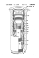
- FIG. 1 is an isometric view of a subsea wellhead housing surrounding the upper ends of three concentric strings of well casing, with the right half and upper portion of the left half of the drawing in vertical central section to show the packoff assemblies of the present invention installed between the housing and the casing hangers.
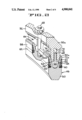
- FIG. 2 is an enlarged fragmentary isometric view in vertical section of one of the packoff assemblies of FIG. 1.
- FIG. 3 is an enlarged fragmentary view in vertical section showing the packoff assembly of FIGS. 1 and 2 in landed position between the wellhead housing and the adjacent casing hanger, but prior to setting it into functional metal-to-metal sealing condition.
- FIG. 4 is a view like FIG. 3, showing the packoff set in its metal-to-metal sealing condition.
- FIGS. 5-7 are enlarged fragmentary views in vertical section illustrating additional embodiments of the metal seal element of a packoff assembly according to this invention.
- FIG. 1 illustrates a typical subsea wellhead system for suspending three casing strings at the seafloor, the system generally comprising an outer wellhead housing 10, first, second and third casing hangers 12, 14 and 16 for supporting outer, intermediate and inner casing strings 18, 20 and 22, respectively, in the housing 10, and first, second and third identical packoff assemblies 24, 26 and 28 for pressure sealing the annuli between the housing 10 and the hangers 12, 14 and 16, respectively.
- first, second and third identical packoff assemblies 24, 26 and 28 for pressure sealing the annuli between the housing 10 and the hangers 12, 14 and 16, respectively.
- each of the annular packoff assemblies comprises a two-piece body having upper and lower components 30, 32 rotatably interconnected by threads 34, a lock ring 36 surrounding and carried by the upper body component 30, an annular lock ring expander mandrel 38 also surrounding the upper body component 30 and retained on it above the lock ring by a snap ring 40, that resides partially in an inner groove 42 in the mandrel and around an outer cylindrical surface 44 of the upper body 30, and an annular metal seal element 46 secured to the lower end of the lower body component 32 by a plurality of circumferentially spaced stud and nut retainers 48 (only one shown).
- Each of the packoff assemblies further includes an anti-rotation ring 47 releasably secured to the upper body component 30 by a plurality of circumferentially spaced shear pins 49 (only one shown) to prevent relative rotation between the upper and lower body components 30, 32 until the packoff assembly is properly positioned and ready for energizing between the housing 10 and the hanger 14.
- the preferred embodiment of the packoff's seal element 46 comprises an annular metal base portion 50 and a pair of annular metal sealing lips 52, 54 that extend upwardly in a relatively diverging or V-shaped manner from the base 50, a pair of annular elastomeric seals 56, 58 surrounding the outer surfaces of the sealing lips 52, 54, respectively, and a pair of annular wire-mesh or other suitable type of anti-extrusion rings 60,62.
- the seal element 46 further includes a plurality of segmented spacers 64 having a somewhat tall, slender inverted mushroom shape in cross-sectional configuration, the spacers arranged circumferentially between the retainer studs 48.
- Each spacer 64 comprises a lower tapered base portion or head 66 that, in the assembled condition shown in the drawings, resides between the seal lips 52, 54, and a central web portion 68 that extends upwardly from the head 66 into a central annular space 70 defined by a pair of annular legs 72, 74 extending downwardly from the lower end portion 32a of the packoff lower body 32.
- the annular legs 72, 74 of the packoff lower body 32 are dimensioned to fit tightly between the upper end portions 52a, 54a of the seal element sealing lips 52, 54 as seen in FIGS. 2-4, and their lower outer surfaces are tapered or contoured at 72a, 74a to establish a wedge-like relationship with these lips.
- the seal lips 52, 54 are mechanically wedged (spread) apart into pressure tight, metal-to-metal contact with the adjacent surfaces of the housing 10 and the hanger 14.
- Each packoff assembly 24, 26, 28 is installed in the wellhead housing 10 by means of a running tool (not shown) attached to the lower end of a pipe string (not shown) that are controlled and manipulated from the surface drilling platform (not shown), a procedure generally well known in the industry.
- a running tool (not shown) attached to the lower end of a pipe string (not shown) that are controlled and manipulated from the surface drilling platform (not shown), a procedure generally well known in the industry.
- the packoff assembly 26 is lowered on the running tool and landed on the hanger as shown in FIG. 3.
- the packoff lower body 32 is locked against rotation by the cooperative action of an axial groove 14a in the upper outer surface of the hanger 14 and a mating axial rib 32b on the adjacent inner surface of the body 32. Should the rib 32b not be in proper alignment with the groove 14a as the packoff is being lowered, the running tool is rotated by rotation of the running string until the alignment is achieved and the landing step can continue.
- the running tool is then rotated to the right, shearing pins (not shown) that releasably secure it to the packoff.
- the tool aligns with vertical slots 80 (FIG. 1) in the packoff and drops further into it, forcing the expander mandrel 38 down behind the lock ring 36 which, in response, expands fully into its wellhead housing groove 82, and causing the packoff anti-rotation ring 47 to shear the pins 49 and drop onto the upper end of the casing hanger 14 (FIG. 4) which thereby frees the packoff's upper body 30 to rotate.
- the running tool is then further rotated to the right, causing corresponding right-hand rotation of the packoff's upper body 30.
- the threads 34 between the upper body 30 and the lower body 32 cause these bodies to move in axial opposite directions, resulting in establishing a compressive force contained between the lock ring 36 and the casing hanger 14.
- This compressive force actuates the packoff seal element 46 to effect the desired metal-to-metal sealing engagement with the wellhead housing 10 and the hanger 14.
- Low torque is sufficient to achieve this seal element actuation, a highly desireable advantage with packoff assemblies of the present invention.
- the packoff assemblies of this invention can be removed from their set position in the wellhead housing 10 (FIG. 4) by lifting the expander mandrel 38 from behind the lock ring 36, allowing the ring to contract out of the housing groove 82 into its FIG. 3 position against the upper body surface. This releases the packoff from the housing, and frees it for withdrawal by merely lifting it vertically.
- FIG. 5 illustrates a modification of the packoff seal of FIG. 1-4, wherein annular elastomeric seals 90, 92 with annular surface grooves 90a, 92a are employed with the metal seal element 46 in place of the elastomeric seals 56, 58 and the anti-extrusion rings 60, 62. Also, the spacers 93 of this embodiment do not include a central web as present in the preferred embodiment.
- FIG. 6 illustrates another metal seal element 94 with sealing lips 96, 98 of slightly different configuration than the corresponding lips 52, 54 of the FIGS. 1-4 embodiment.
- This metal seal element 94 also includes a pair of relatively small annular ribs 100, 102 that project upwardly and outwardly from the seal element base 104, and annular elastomeric seals 106, 108 of an undulate surface configuration that reside between the lips and the ribs.
- the lower outer surfaces of the seal energizer portion 110 of the packoff lower body have radiused surfaces 112, 114 that bear against the inside surfaces of the legs 96, 98.
- the sealing lips 116, 118 of the uniquely shaped metal seal element 120 extend from near the outer edges of the elements base 122, and annular elastomeric seals 124, 126 with annular anti-extrusion rings 128, 130 are held captive between the ends of the lips and opposed shoulders 132, 134 on the seal energizer portion 136 of the packoff's lower body 138.
- FIGS. 5-7 differ in geometry from the preferred embodiment of FIGS. 1-4, it should be understood that the several corresponding parts and surfaces of these further embodiments provide the same functions in response to the same energization as that of the preferred embodiment.
Abstract
Description
Claims (8)
Priority Applications (1)
| Application Number | Priority Date | Filing Date | Title |
|---|---|---|---|
| US07/283,047 US4900041A (en) | 1988-04-27 | 1988-12-06 | Subsea well casing hanger packoff system |
Applications Claiming Priority (2)
| Application Number | Priority Date | Filing Date | Title |
|---|---|---|---|
| US18699388A | 1988-04-27 | 1988-04-27 | |
| US07/283,047 US4900041A (en) | 1988-04-27 | 1988-12-06 | Subsea well casing hanger packoff system |
Related Parent Applications (1)
| Application Number | Title | Priority Date | Filing Date |
|---|---|---|---|
| US18699388A Continuation | 1988-04-27 | 1988-04-27 |
Publications (1)
| Publication Number | Publication Date |
|---|---|
| US4900041A true US4900041A (en) | 1990-02-13 |
Family
ID=26882630
Family Applications (1)
| Application Number | Title | Priority Date | Filing Date |
|---|---|---|---|
| US07/283,047 Expired - Lifetime US4900041A (en) | 1988-04-27 | 1988-12-06 | Subsea well casing hanger packoff system |
Country Status (1)
| Country | Link |
|---|---|
| US (1) | US4900041A (en) |
Cited By (36)
| Publication number | Priority date | Publication date | Assignee | Title |
|---|---|---|---|---|
| US5092401A (en) * | 1989-08-17 | 1992-03-03 | Shell Oil Company | Wellhead assembly |
| GB2256664A (en) * | 1991-05-29 | 1992-12-16 | Seaboard Lloyd Ltd | Hanger lock |
| US5174376A (en) * | 1990-12-21 | 1992-12-29 | Fmc Corporation | Metal-to-metal annulus packoff for a subsea wellhead system |
| US5199497A (en) * | 1992-02-14 | 1993-04-06 | Baker Hughes Incorporated | Shape-memory actuator for use in subterranean wells |
| US5224715A (en) * | 1991-01-17 | 1993-07-06 | Cooper Industries, Inc. | Supported-lip low interference metal stab seal |
| US5307879A (en) * | 1993-01-26 | 1994-05-03 | Abb Vetco Gray Inc. | Positive lockdown for metal seal |
| EP0622520A1 (en) * | 1993-04-26 | 1994-11-02 | Cooper Cameron Corporation | Annular sealing assembly |
| US5364110A (en) * | 1992-12-11 | 1994-11-15 | Halliburton Company | Downhole tool metal-to-metal seal |
| US5997003A (en) * | 1993-04-26 | 1999-12-07 | Cooper Cameron Corporation | Annular sealing assembly and methods of sealing |
| WO2000000762A1 (en) * | 1998-06-30 | 2000-01-06 | Shell Internationale Research Maatschappij B.V. | Seal |
| US6367558B1 (en) * | 1999-10-20 | 2002-04-09 | Abb Vetco Gray Inc. | Metal-to-metal casing packoff |
| US6663144B1 (en) | 2000-06-15 | 2003-12-16 | National Coupling Company | Seal retainer for undersea hydraulic coupling |
| US6666276B1 (en) * | 2001-10-19 | 2003-12-23 | John M. Yokley | Downhole radial set packer element |
| US20060191680A1 (en) * | 2005-02-09 | 2006-08-31 | Vetco Gray Inc. | Metal-to-metal seal for bridging hanger or tieback connection |
| US20080135229A1 (en) * | 2006-12-07 | 2008-06-12 | Vetco Gray Inc. | Flex-lock metal seal system for wellhead members |
| US20090267307A1 (en) * | 2008-04-28 | 2009-10-29 | Freudenberg-Nok General Partnership | High Pressure Tube Seal |
| US20100126736A1 (en) * | 2008-11-25 | 2010-05-27 | Vetco Gray Inc. | Bi-Directional Annulus Seal |
| US20100193195A1 (en) * | 2007-07-19 | 2010-08-05 | Cameron International Corporation | Seal system and method |
| US20100327532A1 (en) * | 2009-06-30 | 2010-12-30 | Vetco Gray Inc. | Metal-to-metal annulus seal arrangement |
| US20110180275A1 (en) * | 2010-01-27 | 2011-07-28 | Vetco Gray Inc. | Bi-Metallic Annular Seal and Wellhead System Incorporating Same |
| US20110227296A1 (en) * | 2010-03-22 | 2011-09-22 | Fmc Technologies, Inc. | Bi-directional seal assembly |
| US20110240307A1 (en) * | 2008-03-28 | 2011-10-06 | Cameron International Corporation | Wellhead Hanger Shoulder |
| US20120097399A1 (en) * | 2010-10-25 | 2012-04-26 | Vetco Gray Inc. | Expandable anchoring mechanism |
| US8181970B2 (en) | 2010-04-22 | 2012-05-22 | Freudenberg Oil & Gas, Llc | Unitized bi-directional seal assembly |
| US8307889B2 (en) | 2010-05-13 | 2012-11-13 | Randy Lewkoski | Assembly for controlling annuli between tubulars |
| US20130146306A1 (en) * | 2011-12-07 | 2013-06-13 | Vetco Gray Inc. | Casing hanger lockdown with conical lockdown ring |
| US20150053395A1 (en) * | 2006-11-17 | 2015-02-26 | Petrowell Limited | Seal Element |
| US20160146962A1 (en) * | 2013-07-12 | 2016-05-26 | Fotech Solutions Limited | Monitoring of Hydraulic Fracturing Operations |
| WO2017123480A1 (en) * | 2016-01-11 | 2017-07-20 | Fmc Technologies, Inc. | Hybrid two piece packoff assembly |
| WO2020112619A1 (en) * | 2018-11-29 | 2020-06-04 | Vetco Gray, LLC | Centralizing and protecting sabot |
| US10788150B2 (en) | 2018-03-22 | 2020-09-29 | Freudenberg-Nok General Partnership | Tube seal |
| US10947804B2 (en) | 2018-04-06 | 2021-03-16 | Vetco Gray, LLC | Metal-to-metal annulus wellhead style seal with pressure energized from above and below |
| US20220282812A1 (en) * | 2019-07-08 | 2022-09-08 | SPM Oil & Gas PC LLC | Highly Elastic Metal Seal |
| US11499387B2 (en) * | 2017-03-09 | 2022-11-15 | Cameron International Corporation | Hanger running tool and hanger |
| US20230008109A1 (en) * | 2021-07-09 | 2023-01-12 | Innovex Downhole Solutions, Inc. | Interchangeable packoff assembly for wellheads |
| RU2810770C1 (en) * | 2023-03-07 | 2023-12-28 | Акционерное общество "Нижегородский завод 70-летия Победы" | Method for compacting interwell space, combined sealer and sealing element |
Citations (16)
| Publication number | Priority date | Publication date | Assignee | Title |
|---|---|---|---|---|
| US881060A (en) * | 1908-03-03 | Crosby Steam Gage And Valve Company | Valve. | |
| US2144682A (en) * | 1936-08-12 | 1939-01-24 | Macclatchie Mfg Company | Blow-out preventer |
| CH206792A (en) * | 1938-05-12 | 1939-08-31 | W Weiland Carl | Piston sealing device. |
| US2451888A (en) * | 1945-02-16 | 1948-10-19 | Globe Hoist Co | Piston oil seal and wiper assembly |
| CA578688A (en) * | 1959-06-30 | James Walker And Co. Limited | Hydraulic packings | |
| FR1231867A (en) * | 1959-04-17 | 1960-10-04 | Dispositifs Oleo Pneumatiques | Seals for corrosive fluids |
| US3414276A (en) * | 1964-06-30 | 1968-12-03 | Fmc Corp | Packing for fluid joint |
| US3561776A (en) * | 1968-11-20 | 1971-02-09 | Fluorocarbon Co The | Composite ring seal and method of making |
| DE2237067A1 (en) * | 1972-07-28 | 1974-02-07 | Daimler Benz Ag | CYLINDER HEAD SEAL FOR AN COMBUSTION ENGINE |
| GB1383319A (en) * | 1971-08-18 | 1974-02-12 | Nicholson T P | Sealing means |
| US4103909A (en) * | 1976-09-30 | 1978-08-01 | Borsig Gesellschaft Mit Beschrankter Haftung | Seal for a drive journal of a ball valve |
| US4372563A (en) * | 1981-10-26 | 1983-02-08 | W-K-M Wellhead Systems, Inc. | Packing support for mounting a well casing packing |
| US4410189A (en) * | 1982-05-13 | 1983-10-18 | The United States Of America As Represented By The Administrator Of The National Aeronautics And Space Administration | Resilient seal ring assembly with spring means applying force to wedge member |
| US4480703A (en) * | 1979-08-24 | 1984-11-06 | Smith International, Inc. | Drilling head |
| US4595053A (en) * | 1984-06-20 | 1986-06-17 | Hughes Tool Company | Metal-to-metal seal casing hanger |
| US4655979A (en) * | 1984-11-02 | 1987-04-07 | Misawa Home Kabushiki Kaisha | Process for production of cellular concrete |
-
1988
- 1988-12-06 US US07/283,047 patent/US4900041A/en not_active Expired - Lifetime
Patent Citations (16)
| Publication number | Priority date | Publication date | Assignee | Title |
|---|---|---|---|---|
| CA578688A (en) * | 1959-06-30 | James Walker And Co. Limited | Hydraulic packings | |
| US881060A (en) * | 1908-03-03 | Crosby Steam Gage And Valve Company | Valve. | |
| US2144682A (en) * | 1936-08-12 | 1939-01-24 | Macclatchie Mfg Company | Blow-out preventer |
| CH206792A (en) * | 1938-05-12 | 1939-08-31 | W Weiland Carl | Piston sealing device. |
| US2451888A (en) * | 1945-02-16 | 1948-10-19 | Globe Hoist Co | Piston oil seal and wiper assembly |
| FR1231867A (en) * | 1959-04-17 | 1960-10-04 | Dispositifs Oleo Pneumatiques | Seals for corrosive fluids |
| US3414276A (en) * | 1964-06-30 | 1968-12-03 | Fmc Corp | Packing for fluid joint |
| US3561776A (en) * | 1968-11-20 | 1971-02-09 | Fluorocarbon Co The | Composite ring seal and method of making |
| GB1383319A (en) * | 1971-08-18 | 1974-02-12 | Nicholson T P | Sealing means |
| DE2237067A1 (en) * | 1972-07-28 | 1974-02-07 | Daimler Benz Ag | CYLINDER HEAD SEAL FOR AN COMBUSTION ENGINE |
| US4103909A (en) * | 1976-09-30 | 1978-08-01 | Borsig Gesellschaft Mit Beschrankter Haftung | Seal for a drive journal of a ball valve |
| US4480703A (en) * | 1979-08-24 | 1984-11-06 | Smith International, Inc. | Drilling head |
| US4372563A (en) * | 1981-10-26 | 1983-02-08 | W-K-M Wellhead Systems, Inc. | Packing support for mounting a well casing packing |
| US4410189A (en) * | 1982-05-13 | 1983-10-18 | The United States Of America As Represented By The Administrator Of The National Aeronautics And Space Administration | Resilient seal ring assembly with spring means applying force to wedge member |
| US4595053A (en) * | 1984-06-20 | 1986-06-17 | Hughes Tool Company | Metal-to-metal seal casing hanger |
| US4655979A (en) * | 1984-11-02 | 1987-04-07 | Misawa Home Kabushiki Kaisha | Process for production of cellular concrete |
Cited By (60)
| Publication number | Priority date | Publication date | Assignee | Title |
|---|---|---|---|---|
| US5092401A (en) * | 1989-08-17 | 1992-03-03 | Shell Oil Company | Wellhead assembly |
| US5174376A (en) * | 1990-12-21 | 1992-12-29 | Fmc Corporation | Metal-to-metal annulus packoff for a subsea wellhead system |
| US5224715A (en) * | 1991-01-17 | 1993-07-06 | Cooper Industries, Inc. | Supported-lip low interference metal stab seal |
| GB2256664A (en) * | 1991-05-29 | 1992-12-16 | Seaboard Lloyd Ltd | Hanger lock |
| US5199497A (en) * | 1992-02-14 | 1993-04-06 | Baker Hughes Incorporated | Shape-memory actuator for use in subterranean wells |
| US5364110A (en) * | 1992-12-11 | 1994-11-15 | Halliburton Company | Downhole tool metal-to-metal seal |
| US5307879A (en) * | 1993-01-26 | 1994-05-03 | Abb Vetco Gray Inc. | Positive lockdown for metal seal |
| EP0622520A1 (en) * | 1993-04-26 | 1994-11-02 | Cooper Cameron Corporation | Annular sealing assembly |
| AU671711B2 (en) * | 1993-04-26 | 1996-09-05 | Cooper Cameron Corporation | Annular Sealing Assembly |
| US5997003A (en) * | 1993-04-26 | 1999-12-07 | Cooper Cameron Corporation | Annular sealing assembly and methods of sealing |
| WO2000000762A1 (en) * | 1998-06-30 | 2000-01-06 | Shell Internationale Research Maatschappij B.V. | Seal |
| AU756170B2 (en) * | 1998-06-30 | 2003-01-09 | Shell Internationale Research Maatschappij B.V. | Seal |
| US6367558B1 (en) * | 1999-10-20 | 2002-04-09 | Abb Vetco Gray Inc. | Metal-to-metal casing packoff |
| US6663144B1 (en) | 2000-06-15 | 2003-12-16 | National Coupling Company | Seal retainer for undersea hydraulic coupling |
| US6666276B1 (en) * | 2001-10-19 | 2003-12-23 | John M. Yokley | Downhole radial set packer element |
| US20060191680A1 (en) * | 2005-02-09 | 2006-08-31 | Vetco Gray Inc. | Metal-to-metal seal for bridging hanger or tieback connection |
| US7861789B2 (en) * | 2005-02-09 | 2011-01-04 | Vetco Gray Inc. | Metal-to-metal seal for bridging hanger or tieback connection |
| US9915120B2 (en) * | 2006-11-17 | 2018-03-13 | Weatherford Technology Holdings, Llc | Seal element |
| US20150053395A1 (en) * | 2006-11-17 | 2015-02-26 | Petrowell Limited | Seal Element |
| GB2444826B (en) * | 2006-12-07 | 2011-04-06 | Vetco Gray Inc | Flex-lock metal seal system for wellhead members |
| US20080135229A1 (en) * | 2006-12-07 | 2008-06-12 | Vetco Gray Inc. | Flex-lock metal seal system for wellhead members |
| US7559366B2 (en) * | 2006-12-07 | 2009-07-14 | Vetco Gray Inc. | Flex-lock metal seal system for wellhead members |
| NO340797B1 (en) * | 2006-12-07 | 2017-06-19 | Vetco Gray Inc | Wellhead seal assembly and a wellhead assembly with such seal |
| US8936092B2 (en) * | 2007-07-19 | 2015-01-20 | Cameron International Corporation | Seal system and method |
| US20130118753A1 (en) * | 2007-07-19 | 2013-05-16 | Cameron International Corporation | Seal system and method |
| US8347966B2 (en) * | 2007-07-19 | 2013-01-08 | Cameron International Corporation | Seal system and method |
| US20100193195A1 (en) * | 2007-07-19 | 2010-08-05 | Cameron International Corporation | Seal system and method |
| US20110240307A1 (en) * | 2008-03-28 | 2011-10-06 | Cameron International Corporation | Wellhead Hanger Shoulder |
| US8851182B2 (en) * | 2008-03-28 | 2014-10-07 | Cameron International Corporation | Wellhead hanger shoulder |
| US20090267307A1 (en) * | 2008-04-28 | 2009-10-29 | Freudenberg-Nok General Partnership | High Pressure Tube Seal |
| US8146670B2 (en) | 2008-11-25 | 2012-04-03 | Vetco Gray Inc. | Bi-directional annulus seal |
| US20100126736A1 (en) * | 2008-11-25 | 2010-05-27 | Vetco Gray Inc. | Bi-Directional Annulus Seal |
| US8561995B2 (en) * | 2009-06-30 | 2013-10-22 | Vetco Gray Inc. | Metal-to-metal annulus seal arrangement |
| US20100327532A1 (en) * | 2009-06-30 | 2010-12-30 | Vetco Gray Inc. | Metal-to-metal annulus seal arrangement |
| US20110180275A1 (en) * | 2010-01-27 | 2011-07-28 | Vetco Gray Inc. | Bi-Metallic Annular Seal and Wellhead System Incorporating Same |
| US8622142B2 (en) * | 2010-01-27 | 2014-01-07 | Vetco Gray Inc. | Sealing wellhead members with bi-metallic annular seal |
| US20110227296A1 (en) * | 2010-03-22 | 2011-09-22 | Fmc Technologies, Inc. | Bi-directional seal assembly |
| US9140388B2 (en) | 2010-03-22 | 2015-09-22 | Fmc Technologies, Inc. | Bi-directional seal assembly |
| US8181970B2 (en) | 2010-04-22 | 2012-05-22 | Freudenberg Oil & Gas, Llc | Unitized bi-directional seal assembly |
| US8307889B2 (en) | 2010-05-13 | 2012-11-13 | Randy Lewkoski | Assembly for controlling annuli between tubulars |
| US8640777B2 (en) * | 2010-10-25 | 2014-02-04 | Vetco Gray Inc. | Expandable anchoring mechanism |
| US20120097399A1 (en) * | 2010-10-25 | 2012-04-26 | Vetco Gray Inc. | Expandable anchoring mechanism |
| US8978772B2 (en) * | 2011-12-07 | 2015-03-17 | Vetco Gray Inc. | Casing hanger lockdown with conical lockdown ring |
| US20130146306A1 (en) * | 2011-12-07 | 2013-06-13 | Vetco Gray Inc. | Casing hanger lockdown with conical lockdown ring |
| US20160146962A1 (en) * | 2013-07-12 | 2016-05-26 | Fotech Solutions Limited | Monitoring of Hydraulic Fracturing Operations |
| WO2017123480A1 (en) * | 2016-01-11 | 2017-07-20 | Fmc Technologies, Inc. | Hybrid two piece packoff assembly |
| US10480273B2 (en) | 2016-01-11 | 2019-11-19 | Fmc Technologies, Inc. | Hybrid two piece packoff assembly |
| US11499387B2 (en) * | 2017-03-09 | 2022-11-15 | Cameron International Corporation | Hanger running tool and hanger |
| US10788150B2 (en) | 2018-03-22 | 2020-09-29 | Freudenberg-Nok General Partnership | Tube seal |
| US10947804B2 (en) | 2018-04-06 | 2021-03-16 | Vetco Gray, LLC | Metal-to-metal annulus wellhead style seal with pressure energized from above and below |
| US20200173240A1 (en) * | 2018-11-29 | 2020-06-04 | Vetco Gray, LLC | Centralizing and protecting sabot |
| US10830006B2 (en) * | 2018-11-29 | 2020-11-10 | Vetco Gray, LLC | Centralizing and protecting sabot |
| GB2593392A (en) * | 2018-11-29 | 2021-09-22 | Vetco Gray Llc | Centralizing and protecting sabot |
| AU2019386959B2 (en) * | 2018-11-29 | 2022-04-21 | Vetco Gray, LLC | Centralizing and protecting sabot |
| GB2593392B (en) * | 2018-11-29 | 2022-06-01 | Vetco Gray Llc | Centralizing and protecting sabot |
| WO2020112619A1 (en) * | 2018-11-29 | 2020-06-04 | Vetco Gray, LLC | Centralizing and protecting sabot |
| AU2022202209B2 (en) * | 2018-11-29 | 2023-10-26 | Vetco Gray Llc | Centralizing and protecting sabot |
| US20220282812A1 (en) * | 2019-07-08 | 2022-09-08 | SPM Oil & Gas PC LLC | Highly Elastic Metal Seal |
| US20230008109A1 (en) * | 2021-07-09 | 2023-01-12 | Innovex Downhole Solutions, Inc. | Interchangeable packoff assembly for wellheads |
| RU2810770C1 (en) * | 2023-03-07 | 2023-12-28 | Акционерное общество "Нижегородский завод 70-летия Победы" | Method for compacting interwell space, combined sealer and sealing element |
Similar Documents
| Publication | Publication Date | Title |
|---|---|---|
| US4900041A (en) | Subsea well casing hanger packoff system | |
| US5060724A (en) | Casing hanger seal locking mechanism with detent | |
| US5174376A (en) | Metal-to-metal annulus packoff for a subsea wellhead system | |
| US4455040A (en) | High-pressure wellhead seal | |
| US3797864A (en) | Combined metal and elastomer seal | |
| EP0495274B1 (en) | Supported-lip low interference metal stab seal | |
| US4595063A (en) | Subsea casing hanger suspension system | |
| US4751965A (en) | Wellhead seal assembly | |
| US6510895B1 (en) | Energized sealing cartridge for annulus sealing between tubular well components | |
| US4496162A (en) | Well sealing assembly having resilient seal ring with metal end caps | |
| EP0498878B1 (en) | Well tubing hanger sealing assembly | |
| GB2115454A (en) | Metal-to-metal seal | |
| EP0475557B1 (en) | Method of sealing a casing hanger in a wellhead | |
| US4911245A (en) | Metal seal with soft inlays | |
| GB2410514A (en) | Wellhead casing hanger | |
| EP0290113A2 (en) | Wellhead annular seal | |
| EP0552525B1 (en) | Hanger assembly | |
| EP2522806A2 (en) | Pressure energized interference fit seal | |
| GB2217795A (en) | Packoff seal | |
| US5127478A (en) | Casing suspension system | |
| US5732772A (en) | Dual split tubing hanger | |
| AU2012201735A1 (en) | Casing hanger lockdown slip ring | |
| US5094297A (en) | Casing weight set seal ring | |
| US10605019B2 (en) | Self-locking packer carrier | |
| US4645214A (en) | Wellhead sealing assembly |
Legal Events
| Date | Code | Title | Description |
|---|---|---|---|
| AS | Assignment |
Owner name: FMC CORPORATION, CHICAGO, IL., A CORP. OF DE. Free format text: ASSIGNMENT OF ASSIGNORS INTEREST.;ASSIGNOR:UNDERWOOD, DONALD M.;REEL/FRAME:005221/0889 Effective date: 19881004 Owner name: FMC CORPORATION, CHICAGO, IL., A CORP. OF DE. Free format text: ASSIGNMENT OF ASSIGNORS INTEREST.;ASSIGNORS:HOPKINS, BOB C.;WESTER, RANDY J.;REEL/FRAME:005221/0888 Effective date: 19880502 |
|
| STCF | Information on status: patent grant |
Free format text: PATENTED CASE |
|
| FEPP | Fee payment procedure |
Free format text: PAYOR NUMBER ASSIGNED (ORIGINAL EVENT CODE: ASPN); ENTITY STATUS OF PATENT OWNER: LARGE ENTITY |
|
| FPAY | Fee payment |
Year of fee payment: 4 |
|
| FEPP | Fee payment procedure |
Free format text: PAYER NUMBER DE-ASSIGNED (ORIGINAL EVENT CODE: RMPN); ENTITY STATUS OF PATENT OWNER: LARGE ENTITY Free format text: PAYOR NUMBER ASSIGNED (ORIGINAL EVENT CODE: ASPN); ENTITY STATUS OF PATENT OWNER: LARGE ENTITY |
|
| FPAY | Fee payment |
Year of fee payment: 8 |
|
| FPAY | Fee payment |
Year of fee payment: 12 |
|
| AS | Assignment |
Owner name: FMC TECHNOLOGIES, INC., ILLINOIS Free format text: ASSIGNMENT OF ASSIGNORS INTEREST;ASSIGNOR:FMC CORPORATION;REEL/FRAME:012691/0030 Effective date: 20011126 |