US4900448A - Membrane dehumidification - Google Patents
Membrane dehumidification Download PDFInfo
- Publication number
- US4900448A US4900448A US07/289,467 US28946788A US4900448A US 4900448 A US4900448 A US 4900448A US 28946788 A US28946788 A US 28946788A US 4900448 A US4900448 A US 4900448A
- Authority
- US
- United States
- Prior art keywords
- fibers
- water vapor
- hollow
- pores
- liquid
- Prior art date
- Legal status (The legal status is an assumption and is not a legal conclusion. Google has not performed a legal analysis and makes no representation as to the accuracy of the status listed.)
- Expired - Fee Related
Links
Images

Classifications
-
- F—MECHANICAL ENGINEERING; LIGHTING; HEATING; WEAPONS; BLASTING
- F24—HEATING; RANGES; VENTILATING
- F24F—AIR-CONDITIONING; AIR-HUMIDIFICATION; VENTILATION; USE OF AIR CURRENTS FOR SCREENING
- F24F3/00—Air-conditioning systems in which conditioned primary air is supplied from one or more central stations to distributing units in the rooms or spaces where it may receive secondary treatment; Apparatus specially designed for such systems
- F24F3/12—Air-conditioning systems in which conditioned primary air is supplied from one or more central stations to distributing units in the rooms or spaces where it may receive secondary treatment; Apparatus specially designed for such systems characterised by the treatment of the air otherwise than by heating and cooling
- F24F3/14—Air-conditioning systems in which conditioned primary air is supplied from one or more central stations to distributing units in the rooms or spaces where it may receive secondary treatment; Apparatus specially designed for such systems characterised by the treatment of the air otherwise than by heating and cooling by humidification; by dehumidification
- F24F3/1411—Air-conditioning systems in which conditioned primary air is supplied from one or more central stations to distributing units in the rooms or spaces where it may receive secondary treatment; Apparatus specially designed for such systems characterised by the treatment of the air otherwise than by heating and cooling by humidification; by dehumidification by absorbing or adsorbing water, e.g. using an hygroscopic desiccant
- F24F3/1417—Air-conditioning systems in which conditioned primary air is supplied from one or more central stations to distributing units in the rooms or spaces where it may receive secondary treatment; Apparatus specially designed for such systems characterised by the treatment of the air otherwise than by heating and cooling by humidification; by dehumidification by absorbing or adsorbing water, e.g. using an hygroscopic desiccant with liquid hygroscopic desiccants
-
- B—PERFORMING OPERATIONS; TRANSPORTING
- B01—PHYSICAL OR CHEMICAL PROCESSES OR APPARATUS IN GENERAL
- B01D—SEPARATION
- B01D53/00—Separation of gases or vapours; Recovering vapours of volatile solvents from gases; Chemical or biological purification of waste gases, e.g. engine exhaust gases, smoke, fumes, flue gases, aerosols
- B01D53/26—Drying gases or vapours
- B01D53/268—Drying gases or vapours by diffusion
-
- B—PERFORMING OPERATIONS; TRANSPORTING
- B01—PHYSICAL OR CHEMICAL PROCESSES OR APPARATUS IN GENERAL
- B01D—SEPARATION
- B01D61/00—Processes of separation using semi-permeable membranes, e.g. dialysis, osmosis or ultrafiltration; Apparatus, accessories or auxiliary operations specially adapted therefor
- B01D61/38—Liquid-membrane separation
-
- F—MECHANICAL ENGINEERING; LIGHTING; HEATING; WEAPONS; BLASTING
- F24—HEATING; RANGES; VENTILATING
- F24F—AIR-CONDITIONING; AIR-HUMIDIFICATION; VENTILATION; USE OF AIR CURRENTS FOR SCREENING
- F24F3/00—Air-conditioning systems in which conditioned primary air is supplied from one or more central stations to distributing units in the rooms or spaces where it may receive secondary treatment; Apparatus specially designed for such systems
- F24F3/12—Air-conditioning systems in which conditioned primary air is supplied from one or more central stations to distributing units in the rooms or spaces where it may receive secondary treatment; Apparatus specially designed for such systems characterised by the treatment of the air otherwise than by heating and cooling
- F24F3/14—Air-conditioning systems in which conditioned primary air is supplied from one or more central stations to distributing units in the rooms or spaces where it may receive secondary treatment; Apparatus specially designed for such systems characterised by the treatment of the air otherwise than by heating and cooling by humidification; by dehumidification
- F24F2003/1435—Air-conditioning systems in which conditioned primary air is supplied from one or more central stations to distributing units in the rooms or spaces where it may receive secondary treatment; Apparatus specially designed for such systems characterised by the treatment of the air otherwise than by heating and cooling by humidification; by dehumidification comprising semi-permeable membrane
-
- F—MECHANICAL ENGINEERING; LIGHTING; HEATING; WEAPONS; BLASTING
- F24—HEATING; RANGES; VENTILATING
- F24F—AIR-CONDITIONING; AIR-HUMIDIFICATION; VENTILATION; USE OF AIR CURRENTS FOR SCREENING
- F24F3/00—Air-conditioning systems in which conditioned primary air is supplied from one or more central stations to distributing units in the rooms or spaces where it may receive secondary treatment; Apparatus specially designed for such systems
- F24F3/12—Air-conditioning systems in which conditioned primary air is supplied from one or more central stations to distributing units in the rooms or spaces where it may receive secondary treatment; Apparatus specially designed for such systems characterised by the treatment of the air otherwise than by heating and cooling
- F24F3/14—Air-conditioning systems in which conditioned primary air is supplied from one or more central stations to distributing units in the rooms or spaces where it may receive secondary treatment; Apparatus specially designed for such systems characterised by the treatment of the air otherwise than by heating and cooling by humidification; by dehumidification
- F24F2003/144—Air-conditioning systems in which conditioned primary air is supplied from one or more central stations to distributing units in the rooms or spaces where it may receive secondary treatment; Apparatus specially designed for such systems characterised by the treatment of the air otherwise than by heating and cooling by humidification; by dehumidification by dehumidification only
Definitions
- preferred liquids include polyethylene glycol (PEG), triethylene glycol, other polar glycols, alcohols or glycerols, or a solvent/solute liquid system which may be an aqueous electrolyte solution such as, for example, a solution of alkali metal salt or other such hygroscopic systems.
- PEG polyethylene glycol
- triethylene glycol other polar glycols
- alcohols or glycerols e.glycerols
- solvent/solute liquid system which may be an aqueous electrolyte solution such as, for example, a solution of alkali metal salt or other such hygroscopic systems.
- aqueous electrolyte solution such as, for example, a solution of alkali metal salt or other such hygroscopic systems.
- LiBr Li 2 CO 3
- other species of collecting liquids which would be useful in the present invention might occur to these skilled in the art.
- FIG. 1 is a schematic diagram of a water vapor removal system in accordance with one embodiment of the invention
- FIGS. 4-6 represent greatly magnified fragmentary sectional views of hollow fiber membranes illustrating three alternate removal techniques
- the invention contemplates a method and system for the efficient selective transfer or removal of a condensable vapor of interest from the ambient atmosphere of a conditioned space.
- the illustrated species of interest is water vapor.
- the system may take any one of several forms, each utilizing one or more advantages associated with transfer through the walls of microporous hollow fibers or across microporous membrane materials in conjunction with pressure and/or concentration gradient differentials.
Abstract
The instant invention provides a method and system for dehumidifying air by microphorous organic hollow fibers having a hygroscopic liquid disposed in the pores thereof for providing a concentration gradient sufficient to provide a continuous water removal mechanism.
Description
This application is a division, of application Ser. No. 07/174,920, filed Mar. 29, 1988 pending.
1. Field of the Invention
The present invention relates generally to the separation of gaseous or vapor phase species by means of immobilized liquid membrane (ILM) materials. More particularly, the invention concerns the removal of water vapor from the ambient atmosphere of a conditioned space.
2. Background Art
Numerous approaches to the separation of one gas from a mixture of gases by preferential differential permeation have been investigated over the years. Membrane systems for the separation of gases are potentially attractive because they offer low capital and operating costs, along with low energy consumption requirements. Stabilized immobilized liquid membranes (ILM's) which achieve the simultaneously high permeability and selectivity associated with earlier ILM's together with an extremely high flux in a manner which overcomes the time variable stability problems associated with early ILM's are described in U.S. Pat. No. 4,710,205 assigned to the same assignee as the present invention. That application also describes in detail how the Kelvin effect operates to increase the stability of immobilized liquid membranes with reference to the lowered vapor pressure of the liquid contained in the membrane pores. To the extent that material from that application is required to supply any additional information relevant to the understanding of material in this application, it is hereby incorporated by reference.
The detrimental effect of high relative humidity with respect to the environment of a controlled space, is well known both as to its effects regarding the comfort of the occupants and with respect to items which need to be stored at lower relative humidity to prevent damage from phenomena associated with prolonged high humidity exposure. For these and many other reasons, humidity control has become a necessity for a wide variety of types of conditioned spaces.
Prior to the utilization of membrane-type separation techniques, the most widely practiced method of removing water vapor from a conditioned space involved condensing moisture contained in the atmosphere by cooling the atmosphere below the dew point. This method works very well with respect to the reduction of high humidities to reasonable humidity readings, however, it does require large quantities of energy to be expended to achieve condensation of the moisture.
Other methods include the use of hygroscopic agents or salts to remove moisture from the atmosphere. This technique has been most often associated with the removal of additional water vapor at lower humidities to achieve a relatively dry state. The salts, of course, must also be regenerated or discarded after absorbing quantities of water.
Still there remains a need, however, for a practical, stable, continuously operable system for the removal of condensable gas, especially water vapor, which combines long life with low energy consumption.
The present invention provides a method and apparatus for separating a condensable gas, especially water vapor, in a stable, low cost efficient manner. With respect to the vapor removal method and apparatus of the present invention, in the preferred arrangements the porous membranes considered are those made of hollow fibers containing radial pores in addition to the hollow central axial capillary.
In one embodiment, a hygroscopic collecting liquid is stabilized in the pores of the hollow fibers. When the humid air is addressed and caused to flow past and perpendicular or parallel to the axis of the hollow fibers and external thereto, the water vapor is sorbed by the liquid. The water vapors diffuse across the liquid (due to concentration gradient) and are desorbed in a vacuum which is maintained on the internal axial capillary passages of the hollow fibers, i.e., the hollow side of the fibers. The fibers are normally arranged in parallel bundles much in the manner of the tubes in a shell and tube heat exchanger. For the system of this configuration to be effective, the liquid must have a low vapor pressure so that an adequate vacuum can be maintained to remove the sorbed water or other condensable gas sought to be removed.
In an alternate embodiment, hygroscopic collecting liquid is flowed inside the hollow fibers not wetting the pores, i.e., the pores are gas filled. Upon exposure to humid air, water vapors in the air diffuse through the pores and are absorbed by the liquid and carried away. This system requires regeneration of the hygroscopic liquid to remove the water vapor prior to reuse.
A third embodiment involves the use of a hygroscopic porous membrane system with extremely small pore size (≦0.003 microns) to remove the water vapor. The removal in this embodiment is based on the Kelvin effect or "super" Kelvin effect in which a tremendous reduction of the vapor pressure of the liquid, e.g., water in the pores occurs in hydrophilic membranes having extremely small pores. In this embodiment, water molecules continually condense in the pores of the membrane and are removed continuously by a vacuum introduced on the other side of the membrane. The water in the humid ambient air replenishes the supply in the pores. This enables continuous operation of the system without interruption or loss of vacuum. In this system, the only requirement is that the partial pressure of the water vapor in the ambient atmosphere be higher than the vapor pressure of the water condensing in the pores in order for removal to occur.
With respect to the collecting liquids, preferred liquids include polyethylene glycol (PEG), triethylene glycol, other polar glycols, alcohols or glycerols, or a solvent/solute liquid system which may be an aqueous electrolyte solution such as, for example, a solution of alkali metal salt or other such hygroscopic systems. These include such species as LiBr, Li2 CO3, etc. It will be further appreciated that other species of collecting liquids which would be useful in the present invention might occur to these skilled in the art.
Embodiments described with respect to exposing one side of the porous material to a vacuum may, in many cases, employ a sweep stream of gas of low relative humidity to remove the condensed water vapor rather than employing a vacuum. Water vapor will be continuously removed as long as the partial pressure of the water vapor in the vacuum or sweep gas is lower than the vapor pressure of the water in the condensed liquid. Of course, the greater the differential, the more efficient the removal.
In the drawings:
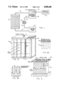
FIG. 1 is a schematic diagram of a water vapor removal system in accordance with one embodiment of the invention;
FIG. 2 is an enlarged perspective detail, with parts cut away, of a hollow fiber membrane filter water vapor removal module in accordance with the invention;
FIG. 2A is a further enlarged fragmentary detail of the hollow fiber bundle of the device of FIG. 2;
FIG. 3 illustrates an alternate stretched fabric membrane configuration of the membrane filter water vapor removal module of FIG. 2;
FIG. 3A is an enlarged detail of the stretched fabric micro porous membrane construction of FIG. 3;
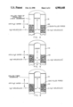
FIGS. 4-6 represent greatly magnified fragmentary sectional views of hollow fiber membranes illustrating three alternate removal techniques;
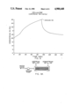
FIGS. 7 and 7A respectively represent a time plot of the relative humidity (RH) of downstream air and a system schematic with respect to the technique of FIG. 4.
FIGS. 8 and 8A respectively represent a time plot of the relative humidity (RH) of downstream air and a system schematic with respect to the technique of FIG. 5.
FIGS. 9 and 9A respectively represent a time plot of the relative humidity (RH) of downstream air and a system schematic with respect to the technique of FIG. 6.
The invention contemplates a method and system for the efficient selective transfer or removal of a condensable vapor of interest from the ambient atmosphere of a conditioned space. The illustrated species of interest is water vapor. The system may take any one of several forms, each utilizing one or more advantages associated with transfer through the walls of microporous hollow fibers or across microporous membrane materials in conjunction with pressure and/or concentration gradient differentials.
One system is depicted schematically in FIG. 1. That system includes a membrane water vapor removal filter module 10, which contains the bundle of hollow fibers or other membrane exchange medium configuration such as a plate and frame system having sections of thin membrane fabric stretched over frames. The water vapor removal module is connected, as by a supply conduit 11, to a source of collecting liquid as a reservoir 12. The collecting fluid may be regenerated to remove absorbed water vapor as through the use of an air bubbler 13, in conjunction with heating element 14. The species of interest (water vapor) is exhausted through external means as by exhaust duct 15. The collecting fluid is circulated, as by means of a variable speed fluid pump 16, which may be a paristaltic pump, through a closed loop system also including conduits 17, 18, and 19, along with fluid filter 20.
It will be appreciated that the collecting fluid may be a one-component medium such as a hygroscopic oil having a high boiling point and one which is compatible with the material of the membrane filters such as cellulose fibers or a polyolefin film or other membrane material. Preferred oil-type liquids include polyethylene glycol (PEG), triethylene glycol, or mixtures thereof. It also is possible to employ various other glycols, alcohols, glycerols, etc. in which the hydroxyl group acts sufficiently as a polar group to make the compound sufficiently hygroscopic. The collecting fluid may also be a solvent/solute liquid system which may be an aqueous electrolyte solution such as, for example, a concentrated aqueous solution of an alkali metal salt or other such hygroscopic systems. Examples of these include such species as LiBr, Li2 CO3, etc. As long as the solvent and dissolved solute species are compatible with the other materials of the system, and the solution will function in the desired humidity range for the conditioned space, it will work successfully
FIGS. 2 and 3 together with respective enlarged detailed fragments 2A, and 3A, depict alternate embodiments 30 and 40, of a membrane filter module as at 10. In FIGS. 2 and 2A, a large number of hollow tubular membrane fibers 31, which may be cellulose, or the like, are disposed in parallel spaced relation much in the fashion of the tube bundle in a shell and tube heat exchanger. In FIG. 3, the configuration is more in the nature of a parallel plate system in which, basically narrow, hollow, rectangular passages are provided having generally hollow interiors as at 41 and sidewalls defined by a membrane of stretched fabric in substantially sheet form as at 42. The membrane covered passages are shown in greater detailed in the fragmentary top view of FIG. 3A.
Normally, the ambient atmosphere containing the water vapor or other species of interest to be removed, or partially removed, is caused to contact the membrane on the outside of the tubes of the tube bundle of FIG. 2 or the parallel plates of FIG. 3, generally perpendicular to and between the fibers or plates to maximize contact area. A closed system in which the atmosphere is caused to flow parallel or counter to the plates or fibers, however, is also possible. This type was used experimentally as it facilitated the taking of data. Flow is normally controlled by a conventional fan or blower (not shown).
In the system of FIG. 1, a hygroscopic liquid having a high boiling point which and is chemically compatible with the material of the fibers or membrane covering is caused to flow vertically from top to bottom inside the hollow individual fibers of the fiber bundle from a supply reservoir 33, (FIG. 2) or from a reservoir 43 through the interior of the openings 41, in FIG. 3.
It will be appreciated with respect to the use of the hollow fiber bundle that this presents a very large sorption area per unit volume for the water vapor or other species to be sorbed through the pores in the fibers. This allows the actual exchange module to be relatively quite compact.
The method of Example 1 is illustrated in the enlarged fragmentary view of the fiber 31 found in FIG. 4. In this example the composition of the fiber material and the collecting liquid are selected such that the collecting liquid wets the pores of the fibers or membrane used. The combination of microporous cellulose fibers with triethylene glycol oil was used in this Example 1. The pores 50 became filled or partially filled with the hydrophilic oil which directly sorbed H2 O vapor molecules from the humid inlet air. In the example a membrane module consisting of 10,800 hollow fibers contained in a plastic jacket was used to make up a counter flow system as shown in FIG. 7A. The hollow fibers were made of cellulose with an average pore size of 0.003 microns. Triethylene glycol (TEG) was stabilized in the pores of the fibers. TEG is one of the few hygroscopic oils which is non-toxic, high-boiling and compatible with cellulose membrane. A vacuum pump as at 60, in FIG. 7A was utilized to maintain a partial vacuum inside the fibers while the air was circulated through a closed system in counter current fashion.
It is seen from FIG. 7 that the humidity in the upstream air is reduced from 100% to 29% upon the one pass through the module. But the humidity on the downstream side increased slowing with time until the vacuum was applied. After the vacuum was applied the downstream humidity was again maintained at a steady 28%.
The sorption of water through the hollow fibers utilizing TEG or other collecting liquid wherein the collecting liquid does not wet the pores and is illustrated in the magnified fragmentary view of FIG. 5. The results of dehumidification utilizing this process are further illustrated in FIG. 8. For that system, a membrane module made of polypropylene hollow fibers was used. The moisture absorbing liquid TEG did not wet the polypropylene membrane pores and was circulated inside the hollow fibers. FIG. 8 reveals that humidity of air in the upstream side was reduced from 95% to, initially, under 15% as the air was flowed through the membrane module. With respect to the data taken in FIG. 5, it is noteworthy that the absorbed water in the TEG was not removed but simply recirculated by the use of a pump. This is shown in the schematic diagram of FIG. 8A wherein the TEG collecting liquid is circulated by pump 72 and the ambient air, inlet 70 and outlet 71. This resulted in the slow increase of the relative humidity of the dry air as the concentration of water vapor in the TEG increased. In a commercial system water vapors in the air continually sorbed by TEG would be removed by regeneration of the TEG as by heating in the presence of air bubbling such as shown in FIG. 1 so that the water vapor is removed continually by the air bubbles exhausted from the oil reservoir.
In yet another embodiment, that of Example 3, no sorption medium is used at all. FIGS. 6, 9 and 9A address this technique. This embodiment makes use of the Kelvin or "super" Kelvin effect described in detail in the above-referenced U.S. Pat. No. 4,710,205, issued Dec. 1, 1987. The feasibility of water vapor removal from here utilizing the system wherein no sorption medium is provided has been demonstrated successfully for fibers or membrane material of sufficiently small pore size. In this situation the vapor pressure of the liquid in the pores is reduced below the partial pressure of the same species, e.g., water vapor, in the ambient air. If the pores are sufficiently small, i.e., ≦ approximately 0.02 microns, preferably less than 0.005, water will continually condense of its own accord in the micro pores 50 and as it is removed by the vacuum internal to the fiber, will continually replenish itself in the pores. In this manner, in effect, water vapor is caused to migrate through the membrane without the need of any collecting liquid. The system holds the vacuum quite well. The data is shown in FIG. 9 and the experimental system illustrated schematically in FIG. 9A. It is substantially identical to that of FIG. 7A including the fiber bundle employed being as described for the embodiment first above except that no collection medium was employed in the pores.
The data shown in FIG. 9 indicates the relative humidity of downstream air as a function of time after the humid air (RH=100%) was passed through the membrane module. The behavior appears similar to that found in FIG. 7, in that it is seen that the relative humidity of the upstream air is reduced from 100% to approximately 21% initially in the downstream air; however, the relative humidity in the downstream air increased slowly with time until the vacuum was applied. Thereafter, the humidity in the downstream air was maintained steadily at 25% by vacuum.
In the case of the technique of FIGS. 6, 9 and 9A, further data relative to flux (water vapor removal), vs. air flow is shown in Table I, next below.
              TABLE I
______________________________________
FLUX (WATER REMOVAL) VS. AIR FLOW
                                    Removal
        V.sub.air
               Humidity % Flux      Rate
        f/m    Up     Down    g/m cm.sup.2
                                      g/m
______________________________________
System*   2.90     98     22    5.88 × 10.sup.-7
          5.80     95     24    10.98
          8.65     90     26    14.76
          40.63    76     55    22.74   0.03
          175.0    76     57    88.8    0.13
Scale Model.sup.+
          ++500                 88.8    3.9
(Parallel Flow)
Scale Model
          500                   ≧888
                                        ≧39
(Cross Flow)
______________________________________
 *Module 8 in. long, 2 in. OD; A = 13,900 cm.sup.2, 10800 fibers, 0.003
 Avg. pore size. (Actual data)
 .sup.+ Scale Model: 1 ft × 1 ft × 1 ft, 10% packing density A
 = 435,000 cm.sup.2 ; 175,000 fibers
 ++ Numbers for scale models are theoretical calculations.
It should be noted that the experiments were carried on utilizing the basic "shell-and-tube" type system so that more precise measurements could readily be made with respect to upstream and downstream humidity and other parameters closely controlled. Other configurations including different types of transfer configurations would occur to those skilled in the art.
Table I demonstrates the feasibility of larger fiber sorbtion modules. It is quite possible for large mega-fiber systems to be used to control the humidity in rather large conditioned spaces using continuous vacuum exhaust, regeneration of the collecting by heating the liquid, or by using a sweep gas to remove excess water vapor from the collecting liquid.
Claims (7)
1. A system for removing water vapor from the ambient atmosphere of a conditioned space comprising:
a transfer medium further comprising a bundle of microporous organic hollow fibers disposed in parallel spaced relation, each fiber being further characterized by a radial microporous matrix structure and a hollow central axial capillary interior;
and means for providing a concentration gradient across the transfer medium sufficient to cause continuous sorption of water on one surface and continuous removal of water from the opposite surface including, a hygroscopic collecting liquid stabilized in the pores of the microporous matrix, said liquid characterized by transport properties favoring the attraction and migration of water vapor molecules and having the ability to wet the material of the pores;
means for establishing a low partial pressure of water vapor in the hollow interior of said fibers such that when the outer surfaces of said fibers are exposed to the ambient atmosphere water vapor molecules are transported through the pores via the collection liquid; and means for removing said water vapor from the hollow interior of said fibers.
2. The system of claim 1 wherein said hygroscopic collection liquid is selected from the group consisting of polar alcohols, glycols, glycerols and solutions consisting of a solvent and solute and the hollow porous fibers are cellulose.
3. The system of claim 1 wherein said hygroscopic collection liquid is selected from polyethylene glycol and triethylene glycol and the hollow porous fibers are cellulose.
4. A system for removing water vapor from the ambient atmosphere of a conditioned space comprising:
a transfer medium further comprising a bundle of organic microporous hollow fibers disposed in parallel spaced relation, each such fiber being further characterized by a radial microporous matrix structure and a hollow central axial capillary interior;
and means for providing a concentration gradient across the transfer medium sufficient to cause continuous sorption of water on one surface and continuous removal of water from the opposite surface including, a hygroscopic collecting liquid stabilized in the pores of the microporous matrix, said liquid characterized by transport properties favoring the attraction and migration of water vapor molecules and having the ability to wet the material of the pores.
means for establishing a vacuum in the hollow interior of said fibers such that when the outer surfaces of said fibers are exposed to the ambient atmosphere water vapor molecules are transported through the pores via the collection liquid and removed from the collection liquid in the interior of said fibers by the vacuum.
5. The system of claim 4 wherein said hygroscopic collection liquid is selected from the group consisting of polar alcohols, glycols, glycerols and solutions consisting of a solvent and solute and the hollow porous fibers are cellulose.
6. A method of removing water from ambient atmosphere comprising the steps of:
exposing the ambient atmosphere to the outside surfaces of a bundle of hollow porous organic fibers each characterized by a radial porous matrix structure and a hollow central axial capillary core; providing a concentration gradient across the transfer medium sufficient to cause continuous sorption of water on one surface of the fibers and continuous surface of said fibers by further providing a hygroscopic transport liquid stabilized in the pores of such fibers, said liquid characterized by attraction and transport properties favoring the migration of water vapor molecules and having the ability to wet the material of said pores; and
exposing the inside surface of said plurality of hollow porous fibers to a medium having a low partial pressure of water vapor to remove migrating water vapor molecules to effluent.
7. The method of claim 6 wherein said low partial pressure of water vapor at the inner surfaces of said hollow porous fibers is achieved by exposing said inner surfaces to a vacuum.
Priority Applications (1)
| Application Number | Priority Date | Filing Date | Title |
|---|---|---|---|
| US07/289,467 US4900448A (en) | 1988-03-29 | 1988-12-21 | Membrane dehumidification |
Applications Claiming Priority (2)
| Application Number | Priority Date | Filing Date | Title |
|---|---|---|---|
| US17492088A | 1988-03-29 | 1988-03-29 | |
| US07/289,467 US4900448A (en) | 1988-03-29 | 1988-12-21 | Membrane dehumidification |
Related Parent Applications (1)
| Application Number | Title | Priority Date | Filing Date |
|---|---|---|---|
| US17492088A Division | 1988-03-29 | 1988-03-29 |
Publications (1)
| Publication Number | Publication Date |
|---|---|
| US4900448A true US4900448A (en) | 1990-02-13 |
Family
ID=26870671
Family Applications (1)
| Application Number | Title | Priority Date | Filing Date |
|---|---|---|---|
| US07/289,467 Expired - Fee Related US4900448A (en) | 1988-03-29 | 1988-12-21 | Membrane dehumidification |
Country Status (1)
| Country | Link |
|---|---|
| US (1) | US4900448A (en) |
Cited By (65)
| Publication number | Priority date | Publication date | Assignee | Title |
|---|---|---|---|---|
| US5104535A (en) * | 1990-08-17 | 1992-04-14 | Zenon Environmental, Inc. | Frameless array of hollow fiber membranes and module containing a stack of arrays |
| US5236474A (en) * | 1991-09-13 | 1993-08-17 | Bend Research, Inc. | Membrane-based removal of condensable vapors |
| WO1994001204A1 (en) * | 1992-07-08 | 1994-01-20 | Nederlandse Organisatie Voor Toegepast- Natuurwetenschappelijk Onderzoek (Tno) | Method and device for regulating the humidity of a gas flow and at the same time purifyng it of undesired acid or alkaline gasses |
| US5395426A (en) * | 1993-07-08 | 1995-03-07 | The United States Of America As Represented By The Secretary Of The Interior | Device for the removal and concentration of organic compounds from the atmosphere |
| US5399188A (en) * | 1993-12-01 | 1995-03-21 | Gas Research Institute | Organic emissions elimination apparatus and process for same |
| US5482859A (en) * | 1990-08-28 | 1996-01-09 | Biller; Edmund | Method and device for feeding gaseous substances into liquid media |
| US5575835A (en) * | 1995-08-11 | 1996-11-19 | W. L. Gore & Associates, Inc. | Apparatus for removing moisture from an environment |
| WO1997048478A1 (en) * | 1996-06-19 | 1997-12-24 | Alliedsignal Inc. | A continuous gas molecule capturing and removal system |
| US5749941A (en) * | 1994-03-25 | 1998-05-12 | Nederlandse Organisatie Voor Toegepast-Natuurwetenschappelijk Onderzoek Tno | Method for gas absorption across a membrane |
| US5928409A (en) * | 1997-11-12 | 1999-07-27 | New Jersey Institute Of Technology | Method and apparatus for gas removal by cyclic flow swing membrane permeation |
| US5935302A (en) * | 1996-12-24 | 1999-08-10 | Samsung Electronics Co., Ltd. | Ion chromatography system for conducting an environmental analysis in semiconductor equipment |
| US5954858A (en) * | 1995-11-22 | 1999-09-21 | North Carolina State University | Bioreactor process for the continuous removal of organic compounds from a vapor phase process stream |
| DE19812960C1 (en) * | 1998-03-24 | 1999-11-04 | Kompressoren Und Druckluft Tec | Membrane drying system for compressed air |
| US6083297A (en) * | 1995-12-13 | 2000-07-04 | Whatman, Inc. | Gas dehydration membrane with low oxygen and nitrogen permeability |
| US6228145B1 (en) * | 1996-07-31 | 2001-05-08 | Kvaerner Asa | Method for removing carbon dioxide from gases |
| US6355092B1 (en) * | 1997-05-09 | 2002-03-12 | Nederlandse Organisatie Voor Toegepast-Natuurwetenschappelijk Ondersoek Tmo | Apparatus and method for performing membrane gas/liquid absorption at elevated pressure |
| WO2002038250A1 (en) * | 2000-11-08 | 2002-05-16 | Clearwater International, L.L.C. | Gas dehydration using membrane and potassium formate solution |
| DE10059910A1 (en) * | 2000-12-01 | 2002-06-20 | Dornier Gmbh | Device for the continuous humidification and dehumidification of the supply air from manufacturing processes and ventilation and air conditioning systems |
| EP1232368A1 (en) * | 1999-11-05 | 2002-08-21 | David A. Thompson | Enthalpy pump |
| US6497749B2 (en) * | 2001-03-30 | 2002-12-24 | United Technologies Corporation | Dehumidification process and apparatus using collodion membrane |
| WO2003008070A1 (en) * | 2001-07-20 | 2003-01-30 | New Jersey Institute Of Technology | Improved membrane separation of carbon dioxide |
| US6517607B2 (en) * | 2001-06-04 | 2003-02-11 | Gas Technology Institute | Method and apparatus for selective removal of a condensable component from a process stream with latent heat recovery |
| US20080034966A1 (en) * | 2006-08-14 | 2008-02-14 | Nanocap Technologies, Llc | Versatile dehumidification process and apparatus |
| US8496732B2 (en) | 2010-11-12 | 2013-07-30 | The Texas A&M University System | Systems and methods for air dehumidification and sensible cooling using a multiple stage pump |
| US8685144B2 (en) | 2010-11-12 | 2014-04-01 | The Texas A&M University System | System and method for efficient air dehumidification and liquid recovery |
| US8685145B2 (en) | 2010-11-12 | 2014-04-01 | The Texas A&M University System | System and method for efficient multi-stage air dehumidification and liquid recovery |
| US8685142B2 (en) | 2010-11-12 | 2014-04-01 | The Texas A&M University System | System and method for efficient air dehumidification and liquid recovery with evaporative cooling |
| US20140157985A1 (en) * | 2011-05-03 | 2014-06-12 | University Of Mississippi | Dehumidification Systems and Methods Thereof |
| US8800308B2 (en) | 2010-05-25 | 2014-08-12 | 7Ac Technologies, Inc. | Methods and systems for desiccant air conditioning with combustion contaminant filtering |
| US20140238235A1 (en) * | 2013-02-22 | 2014-08-28 | Battelle Memorial Institute | Membrane device and process for mass exchange, separation, and filtration |
| EP2777799A1 (en) * | 2013-03-15 | 2014-09-17 | Carrier Corporation | Membrane contactor for dehumidification systems |
| US20140283690A1 (en) * | 2013-03-20 | 2014-09-25 | Carrier Corporation | Membrane contactor for dehumidification systems |
| US9101874B2 (en) | 2012-06-11 | 2015-08-11 | 7Ac Technologies, Inc. | Methods and systems for turbulent, corrosion resistant heat exchangers |
| WO2016098001A1 (en) * | 2014-12-15 | 2016-06-23 | Panacea Quantum Leap Technology Llc | Device for extracting water from the environment |
| US9470426B2 (en) | 2013-06-12 | 2016-10-18 | 7Ac Technologies, Inc. | In-ceiling liquid desiccant air conditioning system |
| US9506697B2 (en) | 2012-12-04 | 2016-11-29 | 7Ac Technologies, Inc. | Methods and systems for cooling buildings with large heat loads using desiccant chillers |
| US9631848B2 (en) | 2013-03-01 | 2017-04-25 | 7Ac Technologies, Inc. | Desiccant air conditioning systems with conditioner and regenerator heat transfer fluid loops |
| CN106855345A (en) * | 2015-12-09 | 2017-06-16 | 财团法人工业技术研究院 | Drying device and drying method |
| US9709285B2 (en) | 2013-03-14 | 2017-07-18 | 7Ac Technologies, Inc. | Methods and systems for liquid desiccant air conditioning system retrofit |
| JP2018094535A (en) * | 2016-12-16 | 2018-06-21 | 株式会社東芝 | Steam separator |
| JP2018094539A (en) * | 2016-12-16 | 2018-06-21 | 株式会社東芝 | Steam separator |
| JP2018094534A (en) * | 2016-12-16 | 2018-06-21 | 株式会社東芝 | Steam separator |
| US10024558B2 (en) | 2014-11-21 | 2018-07-17 | 7Ac Technologies, Inc. | Methods and systems for mini-split liquid desiccant air conditioning |
| US10302317B2 (en) | 2010-06-24 | 2019-05-28 | Nortek Air Solutions Canada, Inc. | Liquid-to-air membrane energy exchanger |
| US10323867B2 (en) | 2014-03-20 | 2019-06-18 | 7Ac Technologies, Inc. | Rooftop liquid desiccant systems and methods |
| US10352628B2 (en) | 2013-03-14 | 2019-07-16 | Nortek Air Solutions Canada, Inc. | Membrane-integrated energy exchange assembly |
| US10584884B2 (en) | 2013-03-15 | 2020-03-10 | Nortek Air Solutions Canada, Inc. | Control system and method for a liquid desiccant air delivery system |
| US10619867B2 (en) | 2013-03-14 | 2020-04-14 | 7Ac Technologies, Inc. | Methods and systems for mini-split liquid desiccant air conditioning |
| CN111089369A (en) * | 2019-12-11 | 2020-05-01 | 浙江理工大学 | Air conditioning system and method |
| US10675583B2 (en) | 2015-03-30 | 2020-06-09 | Panacea Quantum Leap Technology, LLC | Device for the extraction of water from the environment |
| US10712024B2 (en) | 2014-08-19 | 2020-07-14 | Nortek Air Solutions Canada, Inc. | Liquid to air membrane energy exchangers |
| US10782045B2 (en) | 2015-05-15 | 2020-09-22 | Nortek Air Solutions Canada, Inc. | Systems and methods for managing conditions in enclosed space |
| US10808951B2 (en) | 2015-05-15 | 2020-10-20 | Nortek Air Solutions Canada, Inc. | Systems and methods for providing cooling to a heat load |
| US10921001B2 (en) | 2017-11-01 | 2021-02-16 | 7Ac Technologies, Inc. | Methods and apparatus for uniform distribution of liquid desiccant in membrane modules in liquid desiccant air-conditioning systems |
| US10928082B2 (en) | 2011-09-02 | 2021-02-23 | Nortek Air Solutions Canada, Inc. | Energy exchange system for conditioning air in an enclosed structure |
| US10941948B2 (en) | 2017-11-01 | 2021-03-09 | 7Ac Technologies, Inc. | Tank system for liquid desiccant air conditioning system |
| US10962252B2 (en) | 2015-06-26 | 2021-03-30 | Nortek Air Solutions Canada, Inc. | Three-fluid liquid to air membrane energy exchanger |
| US10969124B2 (en) | 2018-09-13 | 2021-04-06 | University Of Mississippi | Vacuum sweep dehumidification system |
| US11022330B2 (en) | 2018-05-18 | 2021-06-01 | Emerson Climate Technologies, Inc. | Three-way heat exchangers for liquid desiccant air-conditioning systems and methods of manufacture |
| US11035618B2 (en) | 2012-08-24 | 2021-06-15 | Nortek Air Solutions Canada, Inc. | Liquid panel assembly |
| EP3851750A1 (en) * | 2020-01-15 | 2021-07-21 | Vestel Elektronik Sanayi ve Ticaret A.S. | Air treatment unit and air control system |
| US11092349B2 (en) | 2015-05-15 | 2021-08-17 | Nortek Air Solutions Canada, Inc. | Systems and methods for providing cooling to a heat load |
| US11408681B2 (en) | 2013-03-15 | 2022-08-09 | Nortek Air Solations Canada, Iac. | Evaporative cooling system with liquid-to-air membrane energy exchanger |
| US11892193B2 (en) | 2017-04-18 | 2024-02-06 | Nortek Air Solutions Canada, Inc. | Desiccant enhanced evaporative cooling systems and methods |
| US11944934B2 (en) | 2021-12-22 | 2024-04-02 | Mojave Energy Systems, Inc. | Electrochemically regenerated liquid desiccant dehumidification system using a secondary heat pump |
Citations (1)
| Publication number | Priority date | Publication date | Assignee | Title |
|---|---|---|---|---|
| US4583996A (en) * | 1983-11-04 | 1986-04-22 | Kabushiki Kaisha Toyota Chuo Kenkyusho | Apparatus for separating condensable gas |
-
1988
- 1988-12-21 US US07/289,467 patent/US4900448A/en not_active Expired - Fee Related
Patent Citations (1)
| Publication number | Priority date | Publication date | Assignee | Title |
|---|---|---|---|---|
| US4583996A (en) * | 1983-11-04 | 1986-04-22 | Kabushiki Kaisha Toyota Chuo Kenkyusho | Apparatus for separating condensable gas |
Cited By (113)
| Publication number | Priority date | Publication date | Assignee | Title |
|---|---|---|---|---|
| US5104535A (en) * | 1990-08-17 | 1992-04-14 | Zenon Environmental, Inc. | Frameless array of hollow fiber membranes and module containing a stack of arrays |
| US5482859A (en) * | 1990-08-28 | 1996-01-09 | Biller; Edmund | Method and device for feeding gaseous substances into liquid media |
| US5236474A (en) * | 1991-09-13 | 1993-08-17 | Bend Research, Inc. | Membrane-based removal of condensable vapors |
| WO1994001204A1 (en) * | 1992-07-08 | 1994-01-20 | Nederlandse Organisatie Voor Toegepast- Natuurwetenschappelijk Onderzoek (Tno) | Method and device for regulating the humidity of a gas flow and at the same time purifyng it of undesired acid or alkaline gasses |
| US5395426A (en) * | 1993-07-08 | 1995-03-07 | The United States Of America As Represented By The Secretary Of The Interior | Device for the removal and concentration of organic compounds from the atmosphere |
| US5399188A (en) * | 1993-12-01 | 1995-03-21 | Gas Research Institute | Organic emissions elimination apparatus and process for same |
| US5749941A (en) * | 1994-03-25 | 1998-05-12 | Nederlandse Organisatie Voor Toegepast-Natuurwetenschappelijk Onderzoek Tno | Method for gas absorption across a membrane |
| US5575835A (en) * | 1995-08-11 | 1996-11-19 | W. L. Gore & Associates, Inc. | Apparatus for removing moisture from an environment |
| US5954858A (en) * | 1995-11-22 | 1999-09-21 | North Carolina State University | Bioreactor process for the continuous removal of organic compounds from a vapor phase process stream |
| US6083297A (en) * | 1995-12-13 | 2000-07-04 | Whatman, Inc. | Gas dehydration membrane with low oxygen and nitrogen permeability |
| WO1997048478A1 (en) * | 1996-06-19 | 1997-12-24 | Alliedsignal Inc. | A continuous gas molecule capturing and removal system |
| US6228145B1 (en) * | 1996-07-31 | 2001-05-08 | Kvaerner Asa | Method for removing carbon dioxide from gases |
| US5935302A (en) * | 1996-12-24 | 1999-08-10 | Samsung Electronics Co., Ltd. | Ion chromatography system for conducting an environmental analysis in semiconductor equipment |
| US6355092B1 (en) * | 1997-05-09 | 2002-03-12 | Nederlandse Organisatie Voor Toegepast-Natuurwetenschappelijk Ondersoek Tmo | Apparatus and method for performing membrane gas/liquid absorption at elevated pressure |
| US5928409A (en) * | 1997-11-12 | 1999-07-27 | New Jersey Institute Of Technology | Method and apparatus for gas removal by cyclic flow swing membrane permeation |
| DE19812960C1 (en) * | 1998-03-24 | 1999-11-04 | Kompressoren Und Druckluft Tec | Membrane drying system for compressed air |
| EP1232368A1 (en) * | 1999-11-05 | 2002-08-21 | David A. Thompson | Enthalpy pump |
| EP1232368A4 (en) * | 1999-11-05 | 2003-01-02 | David A Thompson | Enthalpy pump |
| WO2002038250A1 (en) * | 2000-11-08 | 2002-05-16 | Clearwater International, L.L.C. | Gas dehydration using membrane and potassium formate solution |
| US6666906B2 (en) * | 2000-11-08 | 2003-12-23 | Clearwater International, L.L.C. | Gas dehydration using membrane and potassium formate solution |
| DE10059910A1 (en) * | 2000-12-01 | 2002-06-20 | Dornier Gmbh | Device for the continuous humidification and dehumidification of the supply air from manufacturing processes and ventilation and air conditioning systems |
| DE10059910C2 (en) * | 2000-12-01 | 2003-01-16 | Daimler Chrysler Ag | Device for continuous humidification and dehumidification of the supply air of production processes or ventilation systems |
| US6887303B2 (en) | 2000-12-01 | 2005-05-03 | Daimlerchrysler Ag | Device for continuously humidifying and dehumidifying feed air |
| US20040099140A1 (en) * | 2000-12-01 | 2004-05-27 | Thomas Hesse | Device for continuously humidifying and dehumidifying additional air from manufacturing processes and ventilating and air condition systems |
| US6497749B2 (en) * | 2001-03-30 | 2002-12-24 | United Technologies Corporation | Dehumidification process and apparatus using collodion membrane |
| US6517607B2 (en) * | 2001-06-04 | 2003-02-11 | Gas Technology Institute | Method and apparatus for selective removal of a condensable component from a process stream with latent heat recovery |
| WO2003008070A1 (en) * | 2001-07-20 | 2003-01-30 | New Jersey Institute Of Technology | Improved membrane separation of carbon dioxide |
| US20080034966A1 (en) * | 2006-08-14 | 2008-02-14 | Nanocap Technologies, Llc | Versatile dehumidification process and apparatus |
| WO2008021648A1 (en) * | 2006-08-14 | 2008-02-21 | Nanocap Technologies, Llc | Versatile dehumidification process and apparatus |
| JP2010501065A (en) * | 2006-08-14 | 2010-01-14 | ナノキャップ テクノロジーズ リミテッド ライアビリティ カンパニー | Universal dehumidification process and equipment |
| US7758671B2 (en) | 2006-08-14 | 2010-07-20 | Nanocap Technologies, Llc | Versatile dehumidification process and apparatus |
| US9631823B2 (en) | 2010-05-25 | 2017-04-25 | 7Ac Technologies, Inc. | Methods and systems for desiccant air conditioning |
| US8800308B2 (en) | 2010-05-25 | 2014-08-12 | 7Ac Technologies, Inc. | Methods and systems for desiccant air conditioning with combustion contaminant filtering |
| US10168056B2 (en) | 2010-05-25 | 2019-01-01 | 7Ac Technologies, Inc. | Desiccant air conditioning methods and systems using evaporative chiller |
| US9086223B2 (en) | 2010-05-25 | 2015-07-21 | 7Ac Technologies, Inc. | Methods and systems for desiccant air conditioning |
| US9709286B2 (en) | 2010-05-25 | 2017-07-18 | 7Ac Technologies, Inc. | Methods and systems for desiccant air conditioning |
| US9243810B2 (en) | 2010-05-25 | 2016-01-26 | 7AC Technologies | Methods and systems for desiccant air conditioning |
| US9429332B2 (en) | 2010-05-25 | 2016-08-30 | 7Ac Technologies, Inc. | Desiccant air conditioning methods and systems using evaporative chiller |
| US10006648B2 (en) | 2010-05-25 | 2018-06-26 | 7Ac Technologies, Inc. | Methods and systems for desiccant air conditioning |
| US9377207B2 (en) | 2010-05-25 | 2016-06-28 | 7Ac Technologies, Inc. | Water recovery methods and systems |
| US10753624B2 (en) | 2010-05-25 | 2020-08-25 | 7Ac Technologies, Inc. | Desiccant air conditioning methods and systems using evaporative chiller |
| US11624517B2 (en) | 2010-05-25 | 2023-04-11 | Emerson Climate Technologies, Inc. | Liquid desiccant air conditioning systems and methods |
| US9273877B2 (en) | 2010-05-25 | 2016-03-01 | 7Ac Technologies, Inc. | Methods and systems for desiccant air conditioning |
| US8943850B2 (en) | 2010-05-25 | 2015-02-03 | 7Ac Technologies, Inc. | Desalination methods and systems |
| US9000289B2 (en) | 2010-05-25 | 2015-04-07 | 7Ac Technologies, Inc. | Photovoltaic-thermal (PVT) module with storage tank and associated methods |
| US10302317B2 (en) | 2010-06-24 | 2019-05-28 | Nortek Air Solutions Canada, Inc. | Liquid-to-air membrane energy exchanger |
| US8500848B2 (en) | 2010-11-12 | 2013-08-06 | The Texas A&M University System | Systems and methods for air dehumidification and cooling with membrane water vapor rejection |
| US8685142B2 (en) | 2010-11-12 | 2014-04-01 | The Texas A&M University System | System and method for efficient air dehumidification and liquid recovery with evaporative cooling |
| US8496732B2 (en) | 2010-11-12 | 2013-07-30 | The Texas A&M University System | Systems and methods for air dehumidification and sensible cooling using a multiple stage pump |
| US8641806B2 (en) | 2010-11-12 | 2014-02-04 | The Texas A&M University System | Systems and methods for multi-stage air dehumidification and cooling |
| US8685144B2 (en) | 2010-11-12 | 2014-04-01 | The Texas A&M University System | System and method for efficient air dehumidification and liquid recovery |
| US8685145B2 (en) | 2010-11-12 | 2014-04-01 | The Texas A&M University System | System and method for efficient multi-stage air dehumidification and liquid recovery |
| US20140157985A1 (en) * | 2011-05-03 | 2014-06-12 | University Of Mississippi | Dehumidification Systems and Methods Thereof |
| US11761645B2 (en) | 2011-09-02 | 2023-09-19 | Nortek Air Solutions Canada, Inc. | Energy exchange system for conditioning air in an enclosed structure |
| US10928082B2 (en) | 2011-09-02 | 2021-02-23 | Nortek Air Solutions Canada, Inc. | Energy exchange system for conditioning air in an enclosed structure |
| US9101875B2 (en) | 2012-06-11 | 2015-08-11 | 7Ac Technologies, Inc. | Methods and systems for turbulent, corrosion resistant heat exchangers |
| US10443868B2 (en) | 2012-06-11 | 2019-10-15 | 7Ac Technologies, Inc. | Methods and systems for turbulent, corrosion resistant heat exchangers |
| US9308490B2 (en) | 2012-06-11 | 2016-04-12 | 7Ac Technologies, Inc. | Methods and systems for turbulent, corrosion resistant heat exchangers |
| US11098909B2 (en) | 2012-06-11 | 2021-08-24 | Emerson Climate Technologies, Inc. | Methods and systems for turbulent, corrosion resistant heat exchangers |
| US9101874B2 (en) | 2012-06-11 | 2015-08-11 | 7Ac Technologies, Inc. | Methods and systems for turbulent, corrosion resistant heat exchangers |
| US9835340B2 (en) | 2012-06-11 | 2017-12-05 | 7Ac Technologies, Inc. | Methods and systems for turbulent, corrosion resistant heat exchangers |
| US11732972B2 (en) | 2012-08-24 | 2023-08-22 | Nortek Air Solutions Canada, Inc. | Liquid panel assembly |
| US11035618B2 (en) | 2012-08-24 | 2021-06-15 | Nortek Air Solutions Canada, Inc. | Liquid panel assembly |
| US9506697B2 (en) | 2012-12-04 | 2016-11-29 | 7Ac Technologies, Inc. | Methods and systems for cooling buildings with large heat loads using desiccant chillers |
| US10024601B2 (en) | 2012-12-04 | 2018-07-17 | 7Ac Technologies, Inc. | Methods and systems for cooling buildings with large heat loads using desiccant chillers |
| US9492795B2 (en) * | 2013-02-22 | 2016-11-15 | Battelle Memorial Institute | Membrane device and process for mass exchange, separation, and filtration |
| US20140238235A1 (en) * | 2013-02-22 | 2014-08-28 | Battelle Memorial Institute | Membrane device and process for mass exchange, separation, and filtration |
| US9631848B2 (en) | 2013-03-01 | 2017-04-25 | 7Ac Technologies, Inc. | Desiccant air conditioning systems with conditioner and regenerator heat transfer fluid loops |
| US10760830B2 (en) | 2013-03-01 | 2020-09-01 | 7Ac Technologies, Inc. | Desiccant air conditioning methods and systems |
| US10352628B2 (en) | 2013-03-14 | 2019-07-16 | Nortek Air Solutions Canada, Inc. | Membrane-integrated energy exchange assembly |
| US9709285B2 (en) | 2013-03-14 | 2017-07-18 | 7Ac Technologies, Inc. | Methods and systems for liquid desiccant air conditioning system retrofit |
| US10619867B2 (en) | 2013-03-14 | 2020-04-14 | 7Ac Technologies, Inc. | Methods and systems for mini-split liquid desiccant air conditioning |
| US11300364B2 (en) | 2013-03-14 | 2022-04-12 | Nortek Air Solutions Canada, Ine. | Membrane-integrated energy exchange assembly |
| US9308491B2 (en) | 2013-03-15 | 2016-04-12 | Carrier Corporation | Membrane contactor for dehumidification systems |
| EP2777799A1 (en) * | 2013-03-15 | 2014-09-17 | Carrier Corporation | Membrane contactor for dehumidification systems |
| US10584884B2 (en) | 2013-03-15 | 2020-03-10 | Nortek Air Solutions Canada, Inc. | Control system and method for a liquid desiccant air delivery system |
| US11408681B2 (en) | 2013-03-15 | 2022-08-09 | Nortek Air Solations Canada, Iac. | Evaporative cooling system with liquid-to-air membrane energy exchanger |
| US11598534B2 (en) | 2013-03-15 | 2023-03-07 | Nortek Air Solutions Canada, Inc. | Control system and method for a liquid desiccant air delivery system |
| EP2781251A3 (en) * | 2013-03-20 | 2014-11-05 | Carrier Corporation | Membrane contactor for dehumidification systems |
| US9273876B2 (en) * | 2013-03-20 | 2016-03-01 | Carrier Corporation | Membrane contactor for dehumidification systems |
| US20140283690A1 (en) * | 2013-03-20 | 2014-09-25 | Carrier Corporation | Membrane contactor for dehumidification systems |
| US9470426B2 (en) | 2013-06-12 | 2016-10-18 | 7Ac Technologies, Inc. | In-ceiling liquid desiccant air conditioning system |
| US10619868B2 (en) | 2013-06-12 | 2020-04-14 | 7Ac Technologies, Inc. | In-ceiling liquid desiccant air conditioning system |
| US10619895B1 (en) | 2014-03-20 | 2020-04-14 | 7Ac Technologies, Inc. | Rooftop liquid desiccant systems and methods |
| CN110594883B (en) * | 2014-03-20 | 2022-06-14 | 艾默生环境优化技术有限公司 | Combined heat exchanger and water injection system |
| CN110594883A (en) * | 2014-03-20 | 2019-12-20 | 7Ac技术公司 | Roof liquid desiccant system and method |
| US10323867B2 (en) | 2014-03-20 | 2019-06-18 | 7Ac Technologies, Inc. | Rooftop liquid desiccant systems and methods |
| US10712024B2 (en) | 2014-08-19 | 2020-07-14 | Nortek Air Solutions Canada, Inc. | Liquid to air membrane energy exchangers |
| US10731876B2 (en) | 2014-11-21 | 2020-08-04 | 7Ac Technologies, Inc. | Methods and systems for mini-split liquid desiccant air conditioning |
| US10024558B2 (en) | 2014-11-21 | 2018-07-17 | 7Ac Technologies, Inc. | Methods and systems for mini-split liquid desiccant air conditioning |
| WO2016098001A1 (en) * | 2014-12-15 | 2016-06-23 | Panacea Quantum Leap Technology Llc | Device for extracting water from the environment |
| US10617972B2 (en) | 2014-12-15 | 2020-04-14 | Panacea Quantum Leap Technology Llc | Device for extracting water from the environment |
| US10675583B2 (en) | 2015-03-30 | 2020-06-09 | Panacea Quantum Leap Technology, LLC | Device for the extraction of water from the environment |
| US10782045B2 (en) | 2015-05-15 | 2020-09-22 | Nortek Air Solutions Canada, Inc. | Systems and methods for managing conditions in enclosed space |
| US11092349B2 (en) | 2015-05-15 | 2021-08-17 | Nortek Air Solutions Canada, Inc. | Systems and methods for providing cooling to a heat load |
| US11143430B2 (en) | 2015-05-15 | 2021-10-12 | Nortek Air Solutions Canada, Inc. | Using liquid to air membrane energy exchanger for liquid cooling |
| US11815283B2 (en) | 2015-05-15 | 2023-11-14 | Nortek Air Solutions Canada, Inc. | Using liquid to air membrane energy exchanger for liquid cooling |
| US10808951B2 (en) | 2015-05-15 | 2020-10-20 | Nortek Air Solutions Canada, Inc. | Systems and methods for providing cooling to a heat load |
| US10962252B2 (en) | 2015-06-26 | 2021-03-30 | Nortek Air Solutions Canada, Inc. | Three-fluid liquid to air membrane energy exchanger |
| US10995985B2 (en) | 2015-12-09 | 2021-05-04 | Industrial Technology Research Institute | Drying apparatus and drying method |
| CN106855345A (en) * | 2015-12-09 | 2017-06-16 | 财团法人工业技术研究院 | Drying device and drying method |
| JP2018094539A (en) * | 2016-12-16 | 2018-06-21 | 株式会社東芝 | Steam separator |
| JP2018094535A (en) * | 2016-12-16 | 2018-06-21 | 株式会社東芝 | Steam separator |
| JP2018094534A (en) * | 2016-12-16 | 2018-06-21 | 株式会社東芝 | Steam separator |
| US11892193B2 (en) | 2017-04-18 | 2024-02-06 | Nortek Air Solutions Canada, Inc. | Desiccant enhanced evaporative cooling systems and methods |
| US10941948B2 (en) | 2017-11-01 | 2021-03-09 | 7Ac Technologies, Inc. | Tank system for liquid desiccant air conditioning system |
| US10921001B2 (en) | 2017-11-01 | 2021-02-16 | 7Ac Technologies, Inc. | Methods and apparatus for uniform distribution of liquid desiccant in membrane modules in liquid desiccant air-conditioning systems |
| US11022330B2 (en) | 2018-05-18 | 2021-06-01 | Emerson Climate Technologies, Inc. | Three-way heat exchangers for liquid desiccant air-conditioning systems and methods of manufacture |
| US10969124B2 (en) | 2018-09-13 | 2021-04-06 | University Of Mississippi | Vacuum sweep dehumidification system |
| CN111089369A (en) * | 2019-12-11 | 2020-05-01 | 浙江理工大学 | Air conditioning system and method |
| CN111089369B (en) * | 2019-12-11 | 2022-01-14 | 浙江理工大学 | Air conditioning system and method |
| EP3851750A1 (en) * | 2020-01-15 | 2021-07-21 | Vestel Elektronik Sanayi ve Ticaret A.S. | Air treatment unit and air control system |
| US11944934B2 (en) | 2021-12-22 | 2024-04-02 | Mojave Energy Systems, Inc. | Electrochemically regenerated liquid desiccant dehumidification system using a secondary heat pump |
Similar Documents
| Publication | Publication Date | Title |
|---|---|---|
| US4900448A (en) | Membrane dehumidification | |
| US4915838A (en) | Membrane dehumidification | |
| US5281254A (en) | Continuous carbon dioxide and water removal system | |
| US5876486A (en) | Method and apparatus for removing carbon dioxide | |
| US4583996A (en) | Apparatus for separating condensable gas | |
| US4857081A (en) | Separation of water from hydrocarbons and halogenated hydrocarbons | |
| US6165253A (en) | Apparatus for removal of volatile organic compounds from gaseous mixtures | |
| US6539731B2 (en) | Dehumidification process and apparatus | |
| US20020139245A1 (en) | Dehumidification process and apparatus using collodion membrane | |
| US5637224A (en) | Hollow fiber contained liquid membrane pervaporation for removal of volatile organic compounds from aqueous solutions | |
| US9541302B2 (en) | Flat panel contactors and methods | |
| JP2571841B2 (en) | Gas dehydration method | |
| Kneifel et al. | Hollow fiber membrane contactor for air humidity control: Modules and membranes | |
| US5057641A (en) | High pressure facilitated membranes for selective separation and process for the use thereof | |
| Zhang | Fabrication of a lithium chloride solution based composite supported liquid membrane and its moisture permeation analysis | |
| Chen et al. | Immobilized glycerol-based liquid membranes in hollow fibers for selective CO2 separation from CO2–N2 mixtures | |
| US3511031A (en) | Apparatus for removing water vapor from gases | |
| US6432169B1 (en) | Method and process for drying gas | |
| Yang et al. | Hollow fiber contained liquid membrane pervaporation system for the removal of toxic volatile organics from wastewater | |
| Majumdar et al. | Hollow-fiber contained liquid membrane | |
| Cha et al. | Removal of water vapor and VOCs from nitrogen in a hydrophilic hollow fiber gel membrane permeator | |
| JP2002539404A (en) | Air humidifier | |
| WO1994001204A1 (en) | Method and device for regulating the humidity of a gas flow and at the same time purifyng it of undesired acid or alkaline gasses | |
| JPS61146319A (en) | Dehumidifying method | |
| JPH0413006B2 (en) |
Legal Events
| Date | Code | Title | Description |
|---|---|---|---|
| FEPP | Fee payment procedure |
Free format text: PAYOR NUMBER ASSIGNED (ORIGINAL EVENT CODE: ASPN); ENTITY STATUS OF PATENT OWNER: LARGE ENTITY |
|
| FPAY | Fee payment |
Year of fee payment: 4 |
|
| REMI | Maintenance fee reminder mailed | ||
| LAPS | Lapse for failure to pay maintenance fees | ||
| FP | Lapsed due to failure to pay maintenance fee |
Effective date: 19980218 |
|
| STCH | Information on status: patent discontinuation |
Free format text: PATENT EXPIRED DUE TO NONPAYMENT OF MAINTENANCE FEES UNDER 37 CFR 1.362 |