US4900480A - Gas-liquid mixing - Google Patents

Gas-liquid mixing Download PDF

Info

Publication number
US4900480A
US4900480A US07/358,084 US35808489A US4900480A US 4900480 A US4900480 A US 4900480A US 35808489 A US35808489 A US 35808489A US 4900480 A US4900480 A US 4900480A
Authority
US
United States
Prior art keywords
liquid
gas
recirculating
vessel
quiescent
Prior art date
Legal status (The legal status is an assumption and is not a legal conclusion. Google has not performed a legal analysis and makes no representation as to the accuracy of the status listed.)
Expired - Lifetime
Application number
US07/358,084
Inventor
Lawrence M. Litz
Mark K. Weise
Mitchell Adis
Current Assignee (The listed assignees may be inaccurate. Google has not performed a legal analysis and makes no representation or warranty as to the accuracy of the list.)
Praxair Technology Inc
Original Assignee
Union Carbide Corp
Priority date (The priority date is an assumption and is not a legal conclusion. Google has not performed a legal analysis and makes no representation as to the accuracy of the date listed.)
Filing date
Publication date
Application filed by Union Carbide Corp filed Critical Union Carbide Corp
Priority to US07/358,084 priority Critical patent/US4900480A/en
Application granted granted Critical
Publication of US4900480A publication Critical patent/US4900480A/en
Assigned to PRAXAIR TECHNOLOGY, INC. reassignment PRAXAIR TECHNOLOGY, INC. CHANGE OF NAME (SEE DOCUMENT FOR DETAILS). EFFECTIVE ON 06/12/1992 Assignors: UNION CARBIDE INDUSTRIAL GASES TECHNOLOGY CORPORATION
Anticipated expiration legal-status Critical
Expired - Lifetime legal-status Critical Current

Links

Images

Classifications

    • BPERFORMING OPERATIONS; TRANSPORTING
    • B01PHYSICAL OR CHEMICAL PROCESSES OR APPARATUS IN GENERAL
    • B01FMIXING, e.g. DISSOLVING, EMULSIFYING OR DISPERSING
    • B01F23/00Mixing according to the phases to be mixed, e.g. dispersing or emulsifying
    • B01F23/20Mixing gases with liquids
    • B01F23/23Mixing gases with liquids by introducing gases into liquid media, e.g. for producing aerated liquids
    • B01F23/233Mixing gases with liquids by introducing gases into liquid media, e.g. for producing aerated liquids using driven stirrers with completely immersed stirring elements
    • B01F23/2331Mixing gases with liquids by introducing gases into liquid media, e.g. for producing aerated liquids using driven stirrers with completely immersed stirring elements characterised by the introduction of the gas along the axis of the stirrer or along the stirrer elements
    • BPERFORMING OPERATIONS; TRANSPORTING
    • B01PHYSICAL OR CHEMICAL PROCESSES OR APPARATUS IN GENERAL
    • B01FMIXING, e.g. DISSOLVING, EMULSIFYING OR DISPERSING
    • B01F23/00Mixing according to the phases to be mixed, e.g. dispersing or emulsifying
    • B01F23/20Mixing gases with liquids
    • B01F23/23Mixing gases with liquids by introducing gases into liquid media, e.g. for producing aerated liquids
    • B01F23/2366Parts; Accessories
    • B01F23/2368Mixing receptacles, e.g. tanks, vessels or reactors, being completely closed, e.g. hermetically closed
    • BPERFORMING OPERATIONS; TRANSPORTING
    • B01PHYSICAL OR CHEMICAL PROCESSES OR APPARATUS IN GENERAL
    • B01FMIXING, e.g. DISSOLVING, EMULSIFYING OR DISPERSING
    • B01F25/00Flow mixers; Mixers for falling materials, e.g. solid particles
    • B01F25/50Circulation mixers, e.g. wherein at least part of the mixture is discharged from and reintroduced into a receptacle
    • BPERFORMING OPERATIONS; TRANSPORTING
    • B01PHYSICAL OR CHEMICAL PROCESSES OR APPARATUS IN GENERAL
    • B01JCHEMICAL OR PHYSICAL PROCESSES, e.g. CATALYSIS OR COLLOID CHEMISTRY; THEIR RELEVANT APPARATUS
    • B01J19/00Chemical, physical or physico-chemical processes in general; Their relevant apparatus
    • B01J19/0053Details of the reactor
    • B01J19/006Baffles
    • BPERFORMING OPERATIONS; TRANSPORTING
    • B01PHYSICAL OR CHEMICAL PROCESSES OR APPARATUS IN GENERAL
    • B01JCHEMICAL OR PHYSICAL PROCESSES, e.g. CATALYSIS OR COLLOID CHEMISTRY; THEIR RELEVANT APPARATUS
    • B01J19/00Chemical, physical or physico-chemical processes in general; Their relevant apparatus
    • B01J19/18Stationary reactors having moving elements inside
    • B01J19/1868Stationary reactors having moving elements inside resulting in a loop-type movement
    • B01J19/1875Stationary reactors having moving elements inside resulting in a loop-type movement internally, i.e. the mixture circulating inside the vessel such that the upwards stream is separated physically from the downwards stream(s)
    • BPERFORMING OPERATIONS; TRANSPORTING
    • B01PHYSICAL OR CHEMICAL PROCESSES OR APPARATUS IN GENERAL
    • B01JCHEMICAL OR PHYSICAL PROCESSES, e.g. CATALYSIS OR COLLOID CHEMISTRY; THEIR RELEVANT APPARATUS
    • B01J19/00Chemical, physical or physico-chemical processes in general; Their relevant apparatus
    • B01J19/18Stationary reactors having moving elements inside
    • B01J19/20Stationary reactors having moving elements inside in the form of helices, e.g. screw reactors

Abstract

A feed gas stream is introduced directly into a recirculating liquid stream so as to facilitate formation and maintenance of gas bubbles in a dispersed form in a recirculating gas bubble-liquid mixture. By the maintaining of a gas-liquid interface and overhead gas phase in conjunction with a quiescent zone of liquid apart from the portion of liquid in which said mixture is maintained in a recirculating flow condition, the loss of appreciable amounts of gas to the overhead gas phase is avoided.

Description

This is a continuation of application Ser. No. 06/921,198, filed Oct. 21, 1986.
BACKGROUND OF THE INVENTION
1. Field of the Invention
The invention relates to the mixing of gases and liquids. More particularly, it relates to the formation and recirculation of gas bubble-liquid mixtures.
2. Description of the Prior Art
A wide variety of techniques and systems are known in the art for achieving the mixing and/or reacting of gases. Thus, surface aerators, jets and impellers within stirred tanks have been employed for such mixing. When the residence time required for a desired mixing or reaction operation is longer than a few minutes, either on a batch or continuous basis, stirred tank reactors (STR) are commonly employed. As disclosed in "A Mixed Gas-Liquid Stirred Tank Reactor," L. M. Litz, CEP, November, 1985, pp. 36-39, gas is normally fed to a sparger at the bottom of a conventional STR, and a flat-bladed Rushton turbine or other such mixer system is used to shear the gas into small bubbles for dispersion in the liquid phase. Axial flow impellers are commonly employed to facilitate gas dissolution. Further dissolution is said to occur as the gas bubbles rise up through the liquid, but undissolved gas that reaches the gas-liquid interface in the upper part of the STR is normally lost.
The Litz publication refers to a new design STR, called an Advanced Gas Reactor (AGR), that enables gas dissolution and chemical reaction rates to be increased, while gas and power consumption is being reduced. In this AGR system, a down-pumping impeller is employed within a draft tube, with a baffle arrangement at the inlet thereof causing the liquid flowing into the top of the draft tube to form vortices. These vortices cause feed gas from the gas phase above the liquid to pass down through the draft tube. Additional information pertaining to the AGR system is contained in the publication, and in the Litz patent, U.S. Pat. No. 4,454,077, dated June 12, 1984.
It is well known to use such mixing systems for the reaction of oxygen containing gases, such as air, with organic liquids to form various oxygenated products. Typical of such processes are the oxidation of cumene to form cumene hydroperoxide useful as an intermediate in the production of phenol, the oxidation of propionaldehyde to propionic acid, the oxidation of cyclohexane to adipic acid, and the like. Similarly, such mixing systems can be used for the reaction of hydrogen with various organic chemicals or other materials, as in the hydrogenation of edible and non edible fats and oils, or of antioxidants, medicinals, aluminum alkyls, and the like.
When such gas-liquid mixing operations are carried out in relatively simple tanks or towers, the feed gas is typically bubbled in near the bottom of the tank. Mechanical agitation means may be employed to improve gas-liquid mass transfer, to improve heat exchange, or to maintain solid catalysts in suspension in the gas liquid reaction mixture. In some cases, a simple bubble column is employed, with the injected gas rising up through the body of liquid in the tank. In any event, the oxygen, hydrogen, chlorine or other reactive gas reacts directly when in bubble form, or dissolves in the liquid and then reacts, or experiences both forms of activity. Unreacted gas may be recirculated within the liquid phase, to some extent, by the flow of the liquid as influenced by impellers, as in a conventional STR configuration, or additionally by the liquid downflow in the AGR system in which a draft tube is employed.
Gas-liquid mixing operations must include provisions for changes in the volume of liquid resulting from the dispersion of gases therein. Accordingly, a free liquid surface with an overhead gas phase is typically provided for in mixing operations of the type described herein.
A serious limitation as to the amount of oxygen that may be fed into any of the reactor systems described above resides in the fact that many organic compounds can burn, or even explode, when their vapor is admixed with an oxygen-rich gas. It should be noted that little, if any, such safety problem exists when small gas bubbles of high oxygen content are dispersed within the liquid phase of such a flammable material. This is because the liquid phase provides a large heat sink capable of absorbing any rapid energy release that would occur if the gas bubbles were to ignite in the liquid at typical gas bubble concentrations of 5-20 volume %. There is, in addition, a concentration of oxygen in the vapor-gas phase below which combustion will not be sustained, i.e. a lower flammability limit. With respect to many organic materials, this lower flammability limit is in the range of about 8 to 12 volume percent. For safety reasons, reactors typically are fed only as much oxygen as will assure that the unreacted gas does not cause the oxygen in the gas phase to exceed the oxygen concentration of said lower flammability limit. A negative consequence of this limitation is that the oxygen content of the gas bubbles typically falls off considerably from a point of injection of the gas near the bottom of the reactor and the discharge of bubbles at the gas liquid interface near the top of the tank. As a result, the reaction rate and the gas dissolution rate, which typically are dependent upon the oxygen concentration in the gas bubbles, can decline substantially from the bottom to the top of a conventional reactor. It is well known, however, that, in some cases, it would be desirable to carry out a reaction at fairly high gas bubble oxygen concentrations, even up to pure oxygen feed gas, so as to increase the reaction rate or to improve reaction selectivity to the desired reaction rather than to undesired side reactions.
In the AGR system, as pointed out in the Litz publication, the gas that escapes into the gas phase is recirculated back into the liquid via the vortex ingestion path. While the AGR system can thus be employed to overcome the problems associated with loss of gas e.g. oxygen, into the vapor-gas phase, those skilled in the art will appreciate that the gas introduction rate of the AGR system is a function of the vortex characteristics of the system. While the AGR system provides highly desirable process and apparatus for mixing a gas and a liquid, it will thus be seen to require particular design expertise, especially with respect to the application thereof to operations in which a potentially explosive gas mixture could be created in the vapor-gas phase upon the carrying out of particular gas-liquid reactions at desirably high reaction rates. This is particularly so in light of the sensitivity of the AGR system to liquid level changes and of the fact that the vapor phase concentration of oxygen is in equilibrium with the concentration thereof in the liquid phase.
For the reasons above, there is a desire in the art for further gas liquid mixing development, particularly with respect to reactions subject to the potential of gas phase burning or explosions at desirable reaction rates using the reactor systems and techniques known in the art. Such further development would not replace the AGR approach, but would provide an alternative thereto, one not dependent upon the vortex characteristics, liquid level sensitivities and other pertinent factors relating to the AGR approach. While the concerns with respect to potentially explosive vapor-gas phase mixtures in oxygen applications do not generally pertain in hydrogen, chlorine and other gas applications, it is nevertheless desirable in the art to have an alternative approach available also for use in particular non-oxygen gas-liquid applications. Thus, in some instances, it may be desirable to carry out particular reactions in a manner not sensitive to variations in the liquid level existing within the reactor tank. It is also desirable in some instances to assure retention of the feed gas within the reactor volume by virtue of the system design, apart from the characteristics of a vortex as in AGR processing.
It is an object of the invention, therefore, to provide a process and apparatus for the mixing of a gas and liquid without appreciable loss of gas into the overhead gas phase.
It is another object of the invention to provide a process and apparatus for the enhanced mixing of gas and liquid by the use of a draft tube configuration without undue sensitivity to changes in the level of liquid during the processing operation.
It is a further object of the invention to provide a process and apparatus for the reaction of oxygen with organic liquids in which the concentration of oxygen in the vapor-gas phase is maintained below the lower flammability limit pertaining to said organic liquids.
With these and other objects in mind, the invention is hereinafter described in detail, the novel features thereof being particularly pointed out in the appended claims.
SUMMARY OF THE INVENTION
A major portion of a body of liquid, maintained in a recirculating flow condition, is separated from a relatively quiescent portion of said liquid by mechanical means, but with fluid communication therebetween. The quiescent portion of liquid has a gas-liquid interface with an overhead gas phase. A feed gas stream is introduced directly into the major portion of liquid. The bubbles of gas formed in the liquid are maintained essentially in dispersed form in the recirculating liquid in the major portion of said body of liquid. No appreciable loss of gas to the overhead gas phase occurs. In particular embodiments, various means can be employed to enhance the recirculating flow of liquid in said major portion of liquid, including the use of a hollow draft chamber, the retention of said quiescent portion of liquid in a separate surge vessel, and the use of a tube and shell reactor with an externally pumped recirculation stream maintaining the fluid communication with the quiescent portion of liquid in the surge vessel.
BRIEF DESCRIPTION OF THE DRAWINGS
The invention is further described herein with reference to the accompanying drawings in which:
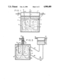
FIG. 1 is a schematic side elevational view of a container vessel representing an embodiment of the invention;
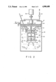
FIG. 2 is a schematic side elevational view of a different container vessel configuration representing another embodiment of the invention, wherein a hollow draft chamber is employed;
FIG. 3 is a schematic side elevational view of a container vessel-surge vessel configuration representing a further embodiment of the invention; and
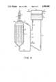
FIG. 4 is a schematic side elevational view of a variation of the configuration of FIG. 3, wherein a shell and tube type vessel is employed as said container vessel.
DETAILED DESCRIPTION OF THE INVENTION
The objects of the invention are accomplished by introducing a feed gas directly into a recirculating portion of a body of liquid separated mechanically from, but in fluid communication with, the remaining portion of said liquid maintained in a separate, relatively quiescent state. The quiescent portion of liquid has a gas liquid interface, with an overhead gas phase. As will be appreciated from the description herein, the major portion of liquid has no such gas-liquid interface and overhead gas phase apart from that provided by said quiescent body of liquid. The major portion of liquid is maintained in a recirculating flow condition, facilitating the formation of gas bubbles upon said direct introduction of feed gas to said liquid. By various means, such gas bubbles are maintained essentially in dispersed form for gas dissolution in, and reaction with, the recirculating liquid in the container vessel. In the practice of the invention, the desired gas-liquid mixing operation is accomplished without appreciable loss of gas to the overhead gas phase.
As will be appreciated from the background discussion above, the invention is particularly advantageous with respect to applications in which an oxygen-containing feed gas is to be fed to a reactor system containing an organic liquid capable of burning, or even exploding, upon admixture of its vapor with an oxygen rich gas. The invention enables the gas-liquid reaction to be carried out without the necessity for employing lower than the desired oxygen concentrations in order to prevent the oxygen in the gas phase from exceeding the lower flammability limit for the particular operation and system. It will be understood, however, that the invention can also be practiced advantageously with respect to hydrogen, chlorine and other gas-liquid reaction applications in which there is no such concern over the development of potentially explosive vapor-gas phase mixtures. As indicated above, there are instances in which it is desirable to carry out a particular reaction in a manner not sensitive to variations on the liquid level existing in the reactor vessel. For such applications, and in those in which it may otherwise be desirable to assure retention of the feed gas within the reactor vessel by virtue of the reactor design, apart from the maintenance of suitable vortex characteristics as in AGR processing, the subject invention provides a highly desirable process and system for carrying out desirable gas-liquid mixing operations.
In one embodiment of the invention, as illustrated in FIG. 1, the major, portion of liquid is separated from said quiescent portion thereof by baffle means positioned within the body of reactive liquid. The body of liquid is represented in said Figure by the numeral 1 and has a major portion 2 separated by mechanical means, i.e. baffle means 3, but in fluid communication with a relatively quiescent portion 4 of said liquid in reactor vessel 5. Said quiescent portion 4 has a gas-liquid interface 6 with overhead gas phase 7. Baffle means 3 are illustrated for convenience as a substantially horizontal partition having opening 8 therein establishing said fluid communication between major portion 2 and quiescent portion 4 of liquid body 1. Said major portion 2 is maintained in a recirculating flow condition, in the illustrated embodiment, by down axial flow impeller 9 that produces the indicated vertical flow pattern. The feed gas stream is introduced through conduit means 10 directly into said major portion 2 of liquid such that the bubbles of gas formed in said liquid are maintained essentially in dispersed form in the recirculating liquid in said major portion of the body of liquid. It will be noted that, in the illustrated embodiment, drive shaft 11 of impeller means 9 extends upward through baffle opening 8 for connection with suitable driving means, not shown.
Baffle means 3 are desirably positioned, with respect to the recirculating stream of liquid and dispersed gas bubbles, so as to obviate the accumulation of individual gas bubbles under said baffle means 3 in excess of about 2 cm3 in volume, preferably in excess of about 1 cm3. By such means, essentially all of the injected gas and the liquid in major portion 2 of liquid body 1 is advantageously involved in the desired gas-liquid mixing and recirculation operation. Baffle means 14 are desirably employed essentially along the walls of vessel 5 and below partition 3 to inhibit the general rotary motion of the gas-liquid phase, to assist in the pumping action of impeller 9, and to avoid the development of a gas filled vortex above impeller 9 and below partition 3. In the practice of the invention, it is generally desirable to pass a small flow of inert gas through overhead gas phase 7 to purge feed gas, or any component thereof, from said overhead phase. For this purpose, inert gas introduction means 12 and inert gas withdrawal, or vent, means 13 are shown in the drawing. When the feed gas comprises an oxygen containing gas, it will be understood that such flow of inert gas is conveniently employed to purge the oxygen content of the overhead gas phase to assure that it remains below the flammability limit thereof.
It will be appreciated that various changes and modifications can be made in the illustrated embodiment of FIG. 1 without departing from the scope of the subject invention. Thus, an axial flow impeller designed to pump the liquid up the center of major portion 2 of liquid body 1, across baffle means 3 and down the region adjacent to the reactor vessel wall could also be conveniently employed. Depending on the reactor vessel size and diameter/height ratio, it may also be desirable to use more than one such axial flow impeller, or other suitable recirculation means, to produce the desired flow patterns and velocities for recirculation of gas bubbles within the reaction vessel. It may also be desirable, in some embodiments, to use a radial flow impeller to provide a region of high shear so as to reduce the size of the gas bubbles, thereby increasing the gas-liquid surface area. Another benefit of gas bubble size reduction, typically in the operating range of 0.1 to 10 mm, is that the recirculating liquid velocity required to carry the bubbles down into the liquid region below baffle means 3 can be desirably reduced. It will also be appreciated that said baffle means 3, illustrated for convenience as a horizontal partition, can be of any other suitable configuration, and the opening or openings therein to establish fluid communication between major portion 2 and quiescent portion 4 of the body of liquid can be varied depending on the overall process and system being employed so long as the desired separation is maintained between said portions of liquid, but with fluid communication therebetween. It will also be appreciated that the opening or openings in said baffle means of the illustrated embodiment can be varied depending upon the requirements of a given application, but will generally comprise a small portion of the cross-sectional area of reactor vessel 5 as compared with that in which the mechanical separation of liquid is maintained by baffle means 3. In this manner, the gas and liquid reactants can be mixed and recirculated without appreciable loss of gas to the overhead gas phase.
A desirable embodiment of the invention that facilitates the establishing of the desired recirculating flow condition in the major portion of the body of liquid is shown in FIG. 2 of the drawings. In this embodiment, the major portion 22 of liquid body 21 is again separated by baffle means 23 from quiescent portion of liquid 24 in reactor vessel 25. Said quiescent portion 24 has a gas-liquid interface 26 with overhead gas phase 27. Opening 28 in said baffle means 23 establish fluid communication between major portion 22 and quiescent portion 24 of said liquid body 21. Major portion 22 is maintained in recirculating flow condition by the essentially central positioning within reactor vessel 25 of a hollow draft chamber 29 such that the open ends thereof, i.e. ends 30 and 31 are at the top and bottom thereof, respectively, and impeller means 32 are positioned within said hollow draft chamber 29. Such impeller means 32 are typically helical impeller means adapted to facilitate the downward flow of the gas bubble-liquid mixture in the draft chamber and upward flow outside said chamber. Impeller means 32 may, if desired, include radial flow impeller means 33 and lower baffle means 40, similar to the guide baffle means referred to below, to reduce the size of the gas bubbles that are maintained in the indicated recirculating flow condition as the gas bubble-liquid mixture in major portion 22 of liquid body 21 is caused to pass downward through hollow draft chamber 29 and up the outer sides of hollow draft chamber 29. The flow of said gas bubble-liquid mixture into the top end 30 and out of the bottom end 31 of said hollow draft chamber 29 is desirably facilitated by the directing of said mixture to top inlet end 30 by guide baffle means 34 positioned at the upper portion of said major portion 22 of liquid body 21 below baffle means 23. As in the FIG. 1 embodiment, said baffle means 23 are desirably positioned so as to obviate the accumulation of individual gas bubbles thereunder in excess of about 2 cm3 in volume.
The feed gas stream is injected directly into major portion 22 of liquid body 21 through conduit means 35 so that the bubbles of gas formed in the liquid are readily maintained essentially in dispersed form in the recirculating liquid in said major portion of the body of liquid. Gas inlet means 36 and outlet vent means 37 are provided to enable inert gas to be passed, if desired, through overhead gas phase 27 to assure that the concentration of oxygen or other inflammable gas is maintained below its flammability limit. Impeller means 32 include a suitable drive shaft 38 that extends upward through opening 28 in baffle means 23, as in the FIG. 1 embodiment, for connection with suitable driving means generally represented by the numeral 39. It, will be noted that hollow draft chamber 29, in particular applications, desirably includes a conically flared portion 30a at the upper end thereof, to further facilitate the flow of the gas bubble-liquid mixture into said draft chamber for downward passage therein.
In the embodiment illustrated in FIG. 3, the major portion, of said body of liquid is separated from the quiescent portion thereof by the retention of the quiescent zone in a separate surge vessel fluidly connected to an essentially liquid filled container or reactor vessel. The surge vessel has therein the gas-liquid interface with an overhead gas phase as discussed above. The container vessel, represented in said FIG. 3 by the numeral 41, contains the major portion 42 of liquid that is in fluid communication with the quiescent portion 43 of liquid maintained in surge vessel 44. Gas-liquid interface 45 separates said quiescent portion of liquid from overhead gas phase 46 in said surge vessel 44. The fluid connection between the vessels includes conduit means 47 in which the flow of the liquid from container vessel 41 is, in preferred applications of the invention, initially in a generally downward direction to facilitate gas-liquid separation, return of gas to said container vessel 41, and then upward flow of essentially gas-free liquid into said surge vessel 44. To preferably pass the liquid from the recirculation circuit back into container vessel 41 without passage of gas back to surge vessel 44, the recirculation circuit includes return conduit means 48 that passes downward from said surge vessel 44 and then generally upward to said container vessel 41. By such a combination of preferred flow paths in the recirculation circuit, the passage of gas bubbles to the surge vessel is desirably minimized. The flow of said liquid in the recirculation circuit is desirably facilitated by recirculation pump means, as by pump means 49 shown positioned in return conduit means 48.
In container vessel 41, impeller means 50, e.g. axial flow impeller means, are used to provide the indicated vertical recirculating flow pattern. The feed gas stream is introduced through conduit means 51 directly into said major portion of liquid 42, as in the other illustrative embodiments referred to above, such that the bubbles of gas formed in the liquid are maintained essentially in dispersed form in the recirculating liquid. As in the FIG. 1 embodiment, baffle means 59 are desirably positioned at points essentially along the walls of container vessel 41 to inhibit any general rotary motion of the gas-liquid phase, to assist in the pumping action of impeller means 50, and to avoid the development of a gas filled vortex above impeller means 50 in said container vessel 41. Inlet means 52 and outlet means 53 can be provided, if desired, to enable purge gas to be passed through overhead gas phase 46 in surge vessel 44 to assure that the reactive gas content therein is maintained below its lower flammability limit.
Impeller means 50 include a drive shaft 54 for connection to suitable driving means, not shown. Drive shaft 54 will be seen to pass through the top of container vessel 41 and through a flame arrestor zone 55 positioned on the top of said container vessel 41. Said flame arrestor zone 55 is employed so as to have a free surface 56 of said body of liquid therein, with a suitable gas discharge conduit 57 above said surface. It will be understood that an annulus 58 will be positioned between the upwardly extending drive shaft 54 and the structure of container vessel 41. Any small amount of gas that escapes from said container vessel 41 through said annulus will, of necessity, pass through said flame arrestor zone 55 having said free surface of liquid and overhead gas therein. Gas escaping from container vessel 41 is conveniently released through discharge means 57 positioned above said free surface 56 of said flame arrestor. Suitable packing may also be employed in said zone. By such a flame arrestor means, the small amount of gas that escapes through the small annulus between the top of the container or reactor vessel and the impeller shaft is prevented from igniting in the proximity of the main body of the gas-liquid mixture that substantially fills said container vessel. Surge vessel 44 provides for the change in volume between the initial condition when no gas bubbles are in the container vessel and the condition that exists when the appropriate gas bubble concentration is developed for a desired reaction. The liquid level in surge vessel 44 can be used as a control on the addition of gas to the container vessel so as to maintain the desired concentration of gas bubbles in the liquid.
Those skilled in the art will appreciate that various changes and modifications can be made to this embodiment, as well as to other embodiments of the invention, without departing from the scope of the invention as recited in the appended claims. For example, if desired to circulate liquid from surge vessel 44 back to container vessel 41 so as to allow it to be oxidized or otherwise treated, pump means 49 can be used as indicated above. Alternatively, the conduit for fluid flow in said recirculation circuit can be made of sufficient, diameter and short length as to permit adequate transfer between said surge vessel and said container vessel by convection and diffusion.
In still another embodiment of the invention illustrated in FIG. 4, the fluid circulation is implemented by means of an external pump instead of by impeller means positioned within the reactor, as in the previously illustrated systems. This embodiment is particularly suitable when a tube and shell reactor design is preferred for high heat-transfer requirements or when a catalyst to be utilized is conveniently packed into the tubes. The tube bundles 62 of tube and shell reactor 61 are adapted for the up-flow of the gas bubble-liquid mixture in the illustrated embodiment, but can be employed in either an up-flowing or down-flowing fashion. Feed mixture is passed to said tubes through lower plenum chamber 63, while upper plenum chamber 64 provides for the discharge of said mixture therefrom. The major portion of liquid in said reactor 61 is separated from the quiescent portion of liquid by the retention of said quiescent portion in separate surge vessel 65 in fluid communication with said reactor 61. Said surge vessel 65 has a gas-liquid interface 66 therein, with an overhead gas phase 67. The overhead gas phase can be purged to maintain the concentration of oxygen or other reactive gas below its lower flammability limit by the passage of a suitable inert gas to said overhead space through inlet conduit means 68, with discharge of gas therefrom through conduit means 69. Fluid communication of said surge vessel 65 with reactor 61 is maintained through fluid communication of said surge vessel 65 with the external recirculation circuit 73 of said tube and shell reactor 61. In a preferred embodiment as illustrated in FIG. 4, the gas-bubble-liquid mixture in said external recirculation circuit is caused to flow from reactor 61 through line 70 for initial fluid communication with overhead flame arrestor zone 71, which has a free surface of liquid 72 therein. Fluid communication between the recirculation circuit and said surge vessel 65 is maintained by separate conduit means 74 adapted for passing a portion of the liquid from recirculation circuit 73 to said surge vessel upstream of said recirculation pump 75. Similarly, conduit 76 is adapted to pass said liquid from said surge vessel to said recirculation circuit 73 downstream of said recirculation pump 75. The flow of said liquid from recirculation circuit 73 into conduit 74 communicating with surge vessel 65 is preferably in a generally downward direction, and the flow of said liquid back into said recirculation circuit from conduit 76 is in a generally upward direction, thereby minimizing the passage of gas bubbles to said surge vessel 65.
In the practice of the FIG. 4 embodiment, the use of flame arrestor zone 71, typically packed to provide flame arrestor characteristics, is a convenient gas vent feature adapted to safely discharge, oxygen-rich gas or other reactive gas through vent 77 when the circulation of the gas bubble-liquid mixture is interrupted. The oxygen-rich or other desired feed gas is introduced into the system at any convenient location, as through line 78 that is positioned so as to assure that the gas bubbles are well dispersed in the liquid in recirculation circuit 73 before the gas bubble-liquid mixture enters plenum chamber 63. In the practice of the invention in this embodiment, as in others, the gas-liquid recirculation system is desirably configured to prevent accumulation of any large gas bubbles, e.g. in excess of 15 mm in diameter, while maintaining an oxygen rich gas bubble concentration, for typical oxidation reaction applications, in the range of about 5 to 20 volume percent. If a down-flowing mode of application is utilized, the minimum flow velocity in said upper plenum chamber 64 and said lower plenum chamber 63, which then would feed and discharge tube bundle 62, has been found in general to be at least 0.3 m/s to insure that the gas bubbles are carried satisfactorily with the liquid into the tubes. It is also generally desirable that recirculation circuit 73 be sized so that the velocity therein is sufficiently high to keep the gas bubbles well dispersed. This desired velocity will vary depending on the physical properties of the fluid involved, but for water-oxygen mixtures, it should generally exceed about 3 m/s. Surge vessel 65 provides for volume expansion when the feed gas is passed into the recirculating liquid, and the volume of gas bubbles within the liquid may be conveniently controlled by observation of the liquid level 66 within said surge vessel 65.
It is generally desirable in applicable embodiments, as in those of FIGS. 1 and 2 of the drawings, to maintain the major -portion of the body of liquid in a recirculating flow condition such as to preclude the existence of any significant passive regions of said major portion of liquid in which essentially no gas bubbles are dispersed in said liquid. It should be noted, however, that the container vessel, may extend deeper than is shown in FIGS. 1 and 2, even though the lower regions in said vessel may contain passive liquid outside the recirculation flow condition created in the major portion of said body of liquid. Such embodiments are operable and are within the scope of the invention as herein disclosed and claimed, although not preferred because of the unused volume of liquid present in the container vessels thereof.
As an illustrative example of the benefits of the invention, 3 liters of 2-ethylhexaldehyde were placed in a 6" diameter reactor of the type shown in FIG. 2. The liquid level prior to the addition of oxygen to the system was about 2 cm above the horizontally positioned baffle means 23. Nitrogen was used as an inert gas to purge the reactor prior to the addition of said aldehyde. A slow nitrogen purge was maintained in overhead gas phase 27 to insure that the oxygen in said gas phase was maintained below 4% by volume. Provisions were made to feed oxygen gas as a stream of bubbles of less than about 6 mm into the liquid phase below said baffle means 23 and at a location where these bubbles would be carried with the recirculating liquid phase in a well dispersed form. A coil in the reactor heated the initial charge to the desired reaction temperature and maintained said temperature during the reaction period. When the liquid reached the desired temperature, the 3" diameter helical impeller was turned on at a rotational speed of 800 RPM, said speed being sufficient to insure that the liquid velocity down hollow draft chamber 29 was in excess of 0.3 mm/s. The pure oxygen feed gas initiated and controlled at a flow rate such that the level of the free liquid surface was maintained about 2 cm above the level existing prior to starting the oxygen flow. This level change corresponded to a change in the total volume below the horizontal baffle 23 of about ten volume percent due to the presence of the gas bubbles therein, said volume being a convenient and readily dispersed concentration of oxygen. As said oxygen was consumed, additional quantities thereof were introduced into the liquid phase in order to hold the liquid level at the desired point. By observing the quantity of oxygen consumed, the degree of reaction can be measured. From the known liquid properties of the mixture of starting materials and the liquid reaction products, changes in liquid volume can be accounted for, and, the control point can be adjusted accordingly. Samples of the liquid phase below the baffle were periodically withdrawn for chemical analysis.
As the reaction proceeded, the oxygen uptake rate fell off, and the rate of oxygen feed was accordingly reduced to maintain the liquid level. Therefore, the oxygen bubble concentration in the liquid phase was maintained essentially constant. The overhead gas phase was continuously monitored to insure that its oxygen concentration did not approach its lower flammability limit. A nitrogen purge rate of about 0.15 l/min was sufficient to assure that the oxygen content of the gas phase was maintained below about 2%. Thus, the practical feasibility of carrying out a typical oxidation process with pure oxygen, or with a high oxygen content gas, in the gas bubbles employed in a gas bubble-liquid mixture, while maintaining the overhead gas phase well below the lower flammability limit of oxygen and the subject organic vapor, was demonstrated in this representative example.
It will be appreciated from the above that the oxygen-containing gas used in particular gas-liquid applications of the invention can be of any suitable oxygen concentration, even up to essentially pure oxygen. Furthermore, such applications can be carried out, in the practice of the invention, under efficient gas bubble formation, dispersion, dissolution and reaction conditions without exceeding the lower flammability limits of the free gas volume above the liquid. The invention also provides, in oxygen applications not involving the potential presence of flammable mixtures in the gas phase and in valuable hydrogenation, chlorination and other practical gas-liquid operations, a highly desirable alternative to various stirred reactor operations and even to the more efficient gas liquid mixing of AGR systems that are more process variable dependent than are the process and system herein described and claimed. The invention thus represents a highly desirable and practical advance in the field of gas-liquid mixing and reaction.

Claims (41)

We claim:
1. An improved process for the introduction of a gas into a body of liquid without appreciable loss of gas into an overhead gas phase comprising:
(a) maintaining a portion of said body of liquid in a recirculating flow condition within a container vessel, said recirculating portion of the body of liquid having no gas-liquid interface with an overhead gas phase, said recirculating portion of the body of liquid being separated by mechanical means, but in fluid communication with, a relatively quiescent portion of said body of liquid, said quiescent portion of the body of liquid having a gas-liquid interface with an overhead gas phase and being adapted to accommodate a change in liquid level in response to a change in the volume of said body of liquid between the condition in which no gas bubbles are in said body of liquid and the condition that exists when a desired gas bubble concentration is developed within said body of liquid; and
(b) introducing a feed gas stream directly into the recirculating portion of said body of liquid and not into said quiescent portion thereof, the recirculation flow path and flow velocity of said recirculating portion of the body of liquid being such, relative to the fluid communication between said recirculating and quiescent portions of the body of liquid, that the bubbles of gas formed upon the introduction of feed gas into said recirculating portion of the body of liquid are maintained in dispersed form in the recirculating liquid, for gas dissolution in, or reaction with, said recirculating portion of the body of liquid, without any appreciable passage of said gas bubbles through the fluid communication between the recirculating portion of the body of liquid and the quiescent portion thereof and through the quiescent portion itself to the gas-liquid interface and thus without loss of gas to the overhead gas phase,
whereby the gas and liquid are advantageously mixed and recirculated in said recirculation portion of the body of liquid without appreciable loss of gas to the overhead gas phase.
2. The process of claim 1 in which said recirculating portion of liquid is separated from said quiescent portion thereof by baffle means positioned within the body of liquid.
3. The process of claim 1 in which said recirculating portion of liquid is maintained in said recirculation flow condition such as to preclude the existence of any significant passive regions of said major portion of liquid in which there are essentially no gas bubbles dispersed in said liquid
4. The process of claim 1 in which said gas comprises an oxygen containing gas.
5. The process of claim 1 and including passing an inert gas through said overhead gas phase to purge said feed gas, or any component thereof, from said overhead gas phase.
6. The process of claim 1 in which said recirculating portion of liquid is maintained in a recirculating flow condition by an axial flow impeller positioned therein.
7. The process of claim 1 in which said recirculating portion of liquid is maintained in a recirculating flow condition by the essentially central positioning therein of a hollow draft chamber such that the open ends of said chamber are at the top and bottom thereof and impeller means positioned within said chamber is operated to cause the gas bubble-liquid mixture in said major portion of liquid to pass through said hollow draft chamber.
8. The process of claim 7 in which the flow of said gas bubble liquid mixture into the top end and out of the bottom end of said draft chamber is facilitated by the directing of said mixture to the upper inlet end of said draft chamber by guide baffle means positioned at the upper portion of said recirculating portion of liquid below said mechanical means.
9. The process of claim 7 in which said recirculating portion of the body of liquid is separated from said quiescent portion thereof by baffle means positioned within said body of liquid, said positioning being such as to obviate the accumulation of individual gas bubbles in excess of about 2 cm3 thereunder.
10. The process of claim 7 in which said gas comprises an oxygen containing gas.
11. The process of claim 7 in which the flow of said gas bubble liquid mixture into the top end and out of the bottom end of said draft chamber is facilitated by the directing of said mixture to the upper inlet end of said draft chamber by guide baffle means positioned at the upper portion of said recirculating portion of liquid below said baffle means, the size of gas bubbles in said mixture being reduced by passing the recirculating gas bubble-liquid mixture through radial flow impeller means and baffle means positioned in the draft chamber below said axial impeller means.
12. The process of claim 1 in which a recirculating portion of said liquid is separated from the quiescent portion thereof by the retention of said quiescent zone in a separate surge vessel fluidly connected to said recirculating liquid in an essentially liquid filled container vessel, said surge vessel having therein said gas liquid interface with an overhead gas phase.
13. The process of claim 12 and including passing an inert gas through said overhead gas phase to purge said feed gas, or any component thereof, from said overhead gas phase.
14. The process of claim 12 in which said feed gas comprises an oxygen containing gas.
15. The process of claim 12 in which the recirculating portion of liquid is caused to fill said container vessel, said liquid being maintained in a recirculating flow condition by an axial flow impeller positioned therein, any gas escaping through the annulus between the container vessel and the shaft of said impeller being passed through a flame arrestor zone having a free surface of liquid therein, said gas being released through the discharge end of said flame arrestor zone.
16. The process of claim 12 in which fluid connection between said container vessel and said surge vessel is maintained through an external recirculation circuit, liquid flowing initially in a generally downward direction from said container vessel in said recirculation circuit for passage to said surge vessel, and liquid passing from said surge vessel in said recirculation circuit to said container vessel, with the flow of liquid from said recirculation circuit into said container vessel being in a generally upward direction.
17. The process of claim 16 in which the flow of said liquid in said recirculation circuit is facilitated by recirculation pump means positioned in said recirculation circuit.
18. The process of claim 1 in which the recirculating or portion of liquid is caused to essentially fill said container vessel, comprising a tube and shell reactor vessel, said gas bubble liquid mixture being maintained in a recirculating flow condition by the pumping of said mixture to and from said reactor vessel in a recirculation circuit external to said reactor vessel by recirculation pump means, the recirculating portion of said liquid being separated from the quiescent portion thereof by the retention of said quiescent portion in a separate surge vessel in fluid communication with said reactor vessel, said surge vessel having therein said gas-liquid interface with an overhead gas phase.
19. The process of claim 18 in which said fluid communication of the surge vessel with said reactor vessel is maintained through fluid communication of said surge vessel with the external recirculation circuit of said reactor vessel.
20. The process of claim 18 in which said feed gas comprises an oxygen containing gas
21. The process of claim 18 in which the gas bubble-liquid mixture is caused to flow from said reactor vessel in said recirculation circuit that is in fluid communication with an overhead flame arrestor zone having a free surface of liquid therein, with fluid communication between said recirculation circuit and said surge vessel being maintained by separate conduit means for passing a portion of said liquid from the recirculation circuit upstream of said recirculation pump means to said surge vessel and for passing said liquid from said surge vessel to said recirculation circuit downstream of said recirculation pump means.
22. The process of claim 21 in which the flow of said liquid from the recirculation circuit into said conduit means communicating with the surge vessel is initially in a generally downward direction, and the flow of said liquid from the conduit means into said regeneration circuit is in a generally upward direction.
23. The process of claim 22 and including venting gas from said flame arrestor zone when the circulation of said gas bubble-liquid mixture is interrupted.
24. An improved apparatus for the introduction of a gas into a body of liquid without appreciable loss of gas into an overhead gas phase comprising:
(a) a container vessel for at least a portion of said body of liquid, said portion to be maintained in a recirculating flow condition for the introduction of a feed gas stream thereto, said recirculation portion of the body of liquid having no gas-liquid interface with an overhead gas phase;
(b) mechanical means for separating said recirculating portion of the body of liquid from a relatively quiescent portion of said body of liquid, while maintaining fluid communication therebetween, said quiescent portion of the body of liquid having a gas-liquid interface and an overhead gas phase space and being adapted to accommodate a change in liquid level in response to a change in the volume of said body of liquid between the condition in which no gas bubbles are in said body of liquid and the condition that exists when a desired gas bubble concentration is developed within said body of liquid;
(c) mechanical means for establishing a recirculating flow condition within said recirculating portion of the body of liquid, the recirculation flow path and flow velocity of said recirculating portion of the body of liquid being such, relative to the fluid communication between said recirculating and quiescent portions of the body of liquid, that the bubbles of gas formed upon the introduction of feed gas into said recirculating portion of the body of liquid are maintained in dispersed form in the recirculating liquid, for gas dissolution in, or reaction with, said recirculating portion of the body of liquid, without any appreciable passage of said gas bubbles through the fluid communication between the recirculating portion of the body of liquid and the quiescent portion thereof and through the quiescent portion itself to the gas-liquid interface and thus without loss of gas to the overhead gas phase; and
(d) conduit means for introducing a feed gas stream directly into said recirculating portion of said body of liquid, and not into the quiescent portion of said body of liquid so that the bubbles of gas are formed in said recirculating portion of the body of liquid and not in said quiescent portion thereof; whereby desired gas and liquid mixing and recirculating is advantageously achieved in the recirculating portion of the body of liquid without appreciable loss of gas to the overhead gas phase.
25. The apparatus of claim 24 in which said mechanical means for separating said portions of the body of liquid comprises baffle means positioned within said container vessel.
26. The apparatus of claim 24 in which said mechanical means for establishing a recirculating flow condition are such as to preclude the existence of any significant passive regions of said recirculating portion of liquid in which essentially no gas bubbles are dispersed in said liquid.
27. The apparatus of claim 24 and including means for passing an inert purge gas through said overhead gas phase.
28. The apparatus of claim 24 in which said mechanical means for establishing a recirculating flow condition comprises axial flow impeller means positioned within said container vessel.
29. The apparatus of claim 24 in which said mechanical means for establishing a recirculating flow condition comprises a hollow draft chamber positioned essentially centrally within said container vessel, said chamber having open ends at the top and bottom thereof as positioned with said container vessel, and impeller means positioned within said chamber and adapted to cause the passage of the gas bubble-liquid mixture in said recirculating portion of liquid to pass through said hollow draft chamber.
30. The apparatus of claim 29 in which said impeller means is adapted to facilitate the flow of said gas bubble-liquid mixture downward in said draft chamber and including guide baffle means for directing said mixture to the top inlet end of said draft chamber.
31. The apparatus of claim 30 in which the hollow draft chamber is conically flared at the upper end thereof.
32. The apparatus of claim 24 and including a separate surge vessel maintained in fluid communication with said container vessel by conduit means, said surge vessel adapted to contain a gas-liquid interface with an overhead gas space within said surge vessel.
33. The apparatus of claim 32 in which said means for establishing a recirculating flow condition comprises axial flow impeller means positioned within said container vessel, and including a packed flame arrestor zone adapted to receive liquid from said container vessel and to maintain a free surface of liquid therein, small amounts of gas passing through the annulus between the container vessel and the shaft of said impeller means passing into said liquid containing flame arrestor zone, and also including means to vent gas above said free surface from said flame arrestor zone.
34. The apparatus of claim 32 in which the conduit means for maintaining fluid communication between said container vessel and said surge vessel comprises separate conduit means for the passage of the liquid from the container vessel to said surge vessel, and for the passage of said liquid back from the surge vessel to said container vessel.
35. The apparatus of claim 34 in which said conduit means from said container vessel to said surge vessel extends initially in a generally downward direction, and said conduit means back to said container vessel extends in a generally upward direction into said container vessel, thereby minimizing the passage of gas bubbles to said surge vessel.
36. The apparatus of claim 24 in which said container vessel comprises a tube and shell reactor vessel, and including an external recirculation circuit for passing the gas bubble-liquid mixture to and from the reactor vessel, the quiescent portion of liquid being retained in a separate surge vessel in fluid communication with said reactor vessel, said surge vessel having therein said gas-liquid interface with an overhead gas phase.
37. The apparatus of claim 36 and including recirculation pump means to pump said mixture through said recirculation circuit.
38. The apparatus of claim 36 in which said recirculation circuit is in fluid communication with a flame arrestor zone, said zone including means for venting gas therefrom.
39. The apparatus of claim 36 and including conduit means to maintain fluid communication between said recirculation circuit and said separate surge vessel.
40. The apparatus of claim 39 which said conduit means comprises separate conduit means for the passage of the liquid from said recirculation circuit to said surge vessel, and for the passage of said liquid back from the surge vessel to said recirculation circuit.
41. The apparatus of claim 40 in which the conduit means from said recirculation circuit to said surge vessel extends initially in a generally downward direction, and said conduit means back to said recirculation circuit from said surge vessel extends in a generally upward direction into said recirculation circuit, thereby minimizing the passage of gas bubbles to said surge vessel.
US07/358,084 1986-10-21 1989-05-30 Gas-liquid mixing Expired - Lifetime US4900480A (en)

Priority Applications (1)

Application Number Priority Date Filing Date Title
US07/358,084 US4900480A (en) 1986-10-21 1989-05-30 Gas-liquid mixing

Applications Claiming Priority (2)

Application Number Priority Date Filing Date Title
US92119886A 1986-10-21 1986-10-21
US07/358,084 US4900480A (en) 1986-10-21 1989-05-30 Gas-liquid mixing

Related Parent Applications (1)

Application Number Title Priority Date Filing Date
US92119886A Continuation 1986-10-21 1986-10-21

Publications (1)

Publication Number Publication Date
US4900480A true US4900480A (en) 1990-02-13

Family

ID=26999922

Family Applications (1)

Application Number Title Priority Date Filing Date
US07/358,084 Expired - Lifetime US4900480A (en) 1986-10-21 1989-05-30 Gas-liquid mixing

Country Status (1)

Country Link
US (1) US4900480A (en)

Cited By (77)

* Cited by examiner, † Cited by third party
Publication number Priority date Publication date Assignee Title
US5009796A (en) * 1986-03-24 1991-04-23 Robert Adler Methods and apparatus for treating a mixture of particles and fluids
US5356600A (en) * 1990-09-24 1994-10-18 Praxair Technology, Inc. Oxygen enrichment method and system
US5371283A (en) * 1993-12-22 1994-12-06 Praxair Technology, Inc. Terephthalic acid production
US5451349A (en) * 1994-08-08 1995-09-19 Praxair Technology, Inc. Advanced gas control in gas-liquid mixing systems
US5523474A (en) * 1994-05-11 1996-06-04 Praxair Technology, Inc. Terephthalic acid production using evaporative cooling
US5536875A (en) * 1994-05-11 1996-07-16 Praxair Technology, Inc. Enhanced oxidation of organic chemicals
US5607233A (en) * 1995-01-30 1997-03-04 Quantum Technologies, Inc. Continuous dynamic mixing system
EP0781754A1 (en) 1995-12-29 1997-07-02 Praxair Technology, Inc. Process and apparatus for the oxidation of alhylaromatic compounps to aromatic carboxylic acids
US5766490A (en) * 1996-01-24 1998-06-16 Life International Products, Inc. Oxygenating apparatus, method for oxygenating water therewith, and applications thereof
US5780683A (en) * 1996-09-11 1998-07-14 Abb Lummus Global Inc. Cyclohexane oxidation
WO1998032725A1 (en) * 1997-01-22 1998-07-30 Bp Chemicals Limited Process for the production of acetic acid
US5814222A (en) * 1995-03-31 1998-09-29 Life International Products, Inc. Oxygen enriched liquids, method and apparatus for making, and applications thereof
US5846498A (en) * 1996-02-27 1998-12-08 Praxair Technology, Inc. Reactor system
US5904851A (en) * 1998-01-19 1999-05-18 Life International Products, Inc. Oxygenating apparatus, method for oxygenating liquid therewith, and applications thereof
EP0974395A2 (en) * 1998-07-23 2000-01-26 Praxair Technology, Inc. Reactor system
EP0995490A2 (en) * 1998-10-20 2000-04-26 Praxair Technology, Inc. Ballast gas use in liquid phase oxidations
US6145815A (en) * 1992-08-17 2000-11-14 Praxair Technology, Inc. System for enhanced gas dissolution having a hood positioned over the impeller with segregating rings
US6158722A (en) * 1998-09-23 2000-12-12 General Signal Corporation Mixing system for introducing and dispersing gas into liquids
US6224041B1 (en) 1999-05-28 2001-05-01 Smith & Loveless, Inc. Splash plate structure for aerators
US6273402B1 (en) 2000-01-10 2001-08-14 Praxair Technology, Inc. Submersible in-situ oxygenator
US6362367B2 (en) 1998-04-21 2002-03-26 Union Carbide Chemicals & Plastics Technology Corp. Preparation of organic acids
KR100374785B1 (en) * 2000-06-29 2003-03-04 학교법인 포항공과대학교 Liquid phase oxidation reactor
US20030175186A1 (en) * 2001-12-26 2003-09-18 Cohen Jeffrey David Process and apparatus for performing a gas-sparged reaction
US20030201554A1 (en) * 2000-10-02 2003-10-30 Eco-Oxygen Technologies, Llc, An Indiana Limited Liability Company Gas dissolving apparatus and method
US6649773B2 (en) 2002-03-22 2003-11-18 General Electric Company Method for the manufacture of halophthalic acids and anhydrides
US6657068B2 (en) 2002-03-22 2003-12-02 General Electric Company Liquid phase oxidation of halogenated ortho-xylenes
US6657067B2 (en) 2002-03-22 2003-12-02 General Electric Company Method for the manufacture of chlorophthalic anhydride
US20040037633A1 (en) * 2002-02-14 2004-02-26 Dr. Jorg Guhring Heavy-duty coupling for tool holder arms of modular design
EP1417980A1 (en) * 2002-11-06 2004-05-12 Sidam di Azzolini Graziano E C. S.a.s. Device for in-line mixing of fluids, in particular medical fluids
US20040130043A1 (en) * 2001-04-19 2004-07-08 Alain Boulant Device for stirring and aerating a liquid in a treatment vessel
US20040155368A1 (en) * 2001-04-19 2004-08-12 Alain Boulant Device for stirring and data aerating a liquid in a treatment vessel
US20060004224A1 (en) * 2004-06-30 2006-01-05 General Electric Company Method of making halophthalic acids and halophthalic anhydrides
US20060004223A1 (en) * 2004-06-30 2006-01-05 General Electric Company Method of making halophthalic acids and halophthalic anhydrides
US20060047150A1 (en) * 2004-09-02 2006-03-02 Wonders Alan G Optimized liquid-phase oxidation
US20060047162A1 (en) * 2004-09-02 2006-03-02 Wonders Alan G Optimized liquid-phase oxidation
US20060047158A1 (en) * 2004-09-02 2006-03-02 Wonders Alan G Optimized liquid-phase oxidation
US20060047157A1 (en) * 2004-09-02 2006-03-02 Wonders Alan G Optimized liquid-phase oxidation
US20060047160A1 (en) * 2004-09-02 2006-03-02 Wonders Alan G Optimized liquid-phase oxidation
US20060047154A1 (en) * 2004-09-02 2006-03-02 Wonders Alan G Optimized liquid-phase oxidation
US20060047149A1 (en) * 2004-09-02 2006-03-02 De Vreede Marcel Optimized liquid-phase oxidation
US20060047159A1 (en) * 2004-09-02 2006-03-02 Wonders Alan G Optimized liquid-phase oxidation
US20060047152A1 (en) * 2004-09-02 2006-03-02 Wonders Alan G Optimized liquid-phase oxidation
US20060047146A1 (en) * 2004-09-02 2006-03-02 Wonders Alan G Optimized liquid-phase oxidation
US20060047151A1 (en) * 2004-09-02 2006-03-02 Wonders Alan G Optimized liquid-phase oxidation
US20060047144A1 (en) * 2004-09-02 2006-03-02 Wonders Alan G Optimized liquid-phase oxidation
US20060047156A1 (en) * 2004-09-02 2006-03-02 Wonders Alan G Optimized liquid-phase oxidation
US20060047155A1 (en) * 2004-09-02 2006-03-02 Wonders Alan G Optimized liquid-phase oxidation
US20060047148A1 (en) * 2004-09-02 2006-03-02 Wonders Alan G Optimized liquid-phase oxidation
US20060047163A1 (en) * 2004-09-02 2006-03-02 De Vreede Marcel Optimized liquid-phase oxidation
US20060047153A1 (en) * 2004-09-02 2006-03-02 Wonders Alan G Optimized liquid-phase oxidation
US20060047143A1 (en) * 2004-09-02 2006-03-02 Wonders Alan G Optimized liquid-phase oxidation
US20060047147A1 (en) * 2004-09-02 2006-03-02 Wonders Alan G Optimized liquid-phase oxidation
US20060047161A1 (en) * 2004-09-02 2006-03-02 Wonders Alan G Optimized liquid-phase oxidation
US20060047142A1 (en) * 2004-09-02 2006-03-02 Wonders Alan G Optimized liquid-phase oxidation
US20060047145A1 (en) * 2004-09-02 2006-03-02 Wonders Alan G Optimized liquid-phase oxidation
US20060116530A1 (en) * 2004-11-29 2006-06-01 Wonders Alan G Optimized liquid-phase oxidation
US20060287552A1 (en) * 2005-06-16 2006-12-21 Wonders Alan G Optimized liquid-phase oxidation
US20070063359A1 (en) * 2005-09-16 2007-03-22 Dowd Robert P Aeration system and method
WO2007054341A1 (en) * 2005-11-10 2007-05-18 Vortex-Nanofluid Gmbh Device and method for producing nanodispersions
US20070155985A1 (en) * 2006-01-04 2007-07-05 Wonders Alan G Oxidation system with internal secondary reactor
US20070161812A1 (en) * 2006-01-10 2007-07-12 Andrew Michael Lemonds Liquid-phase (AMM)oxidation process
US7358389B2 (en) 2006-01-04 2008-04-15 Eastman Chemical Company Oxidation system employing internal structure for enhanced hydrodynamics
US20080161588A1 (en) * 2007-01-02 2008-07-03 Hrd Corp. D/B/A Marcus Oil & Chemical Process and catalyst for production of low trans fat-containing triglycerides
US20090005606A1 (en) * 2007-06-27 2009-01-01 H R D Corporation High shear process for the production of cumene hydroperoxide
US20090032000A1 (en) * 2007-08-03 2009-02-05 Rim Julius J Hydrated EGR system, method and apparatus for reducing harmful exhaust emissions and improving fuel economy
US20090171126A1 (en) * 2007-11-01 2009-07-02 Illa International, Llc Method For Acceleration of Cumene Oxidation
US7608732B2 (en) 2005-03-08 2009-10-27 Eastman Chemical Company Optimized liquid-phase oxidation
EP2137129A1 (en) * 2007-06-27 2009-12-30 H R D Corporation System and process for production of benzoic acids and phthalic acids
US20100180836A1 (en) * 2007-06-15 2010-07-22 Auburn University Fluid storage containers with baffles
US20100324308A1 (en) * 2007-06-27 2010-12-23 H R D Corporation High shear system and method for the production of acids
US20110137077A1 (en) * 2007-08-21 2011-06-09 Basf Se Process and apparatus for oxidizing organic compounds
KR101195892B1 (en) * 2011-06-07 2012-10-30 경상대학교산학협력단 Mixing containers with baffles parallel to the primary rotational flow and an agitator using the same
US20150323938A1 (en) * 2014-05-09 2015-11-12 Honeywell International Inc. Temperature-based level detection and control method and apparatus
CN106163651A (en) * 2014-03-20 2016-11-23 Idec株式会社 Aphron liquid generator
EP3122445A4 (en) * 2014-03-27 2018-01-03 Turbulent Technologies Ltd. Method and apparatus for reduction of air ingestion during mixing
US20190071394A1 (en) * 2017-09-06 2019-03-07 Evonik Degussa Gmbh Process for the preparation of an alkanesulfonic acid
US11105343B2 (en) * 2018-12-14 2021-08-31 Smith Flow Dynamics, LLC Fluid-foil impeller and method of use

Citations (18)

* Cited by examiner, † Cited by third party
Publication number Priority date Publication date Assignee Title
DE243984C (en) *
US697069A (en) * 1901-06-13 1902-04-08 Louis E C Brushaber Apparatus for consuming smoke.
US1471332A (en) * 1923-10-23 Apparatus for treating liquids with gases
US2130402A (en) * 1935-12-11 1938-09-20 Northwest Paper Company Apparatus for chlorinating pulp
FR941828A (en) * 1945-04-06 1949-01-21 Fournier Ferrier Ets Rotary drive device without mechanical connection to the outside to create agitation in a vacuum
US2615698A (en) * 1950-12-28 1952-10-28 Patterson Foundry & Machine Co Apparatus for dispersing gases in liquids
FR1135095A (en) * 1955-11-02 1957-04-24 Rech S De Procedes Ind Et Method and device for the evacuation and purification of fumes and similar gases
US2881057A (en) * 1956-04-12 1959-04-07 Shell Dev Safety vessel
GB1163653A (en) * 1966-02-03 1969-09-10 Fermentation Improvements in or relating to Method and Device for Stirring and Methodically Circulating Liquid Masses Simultaneous Gas Blowing and Mechanical Propulsion.
US3681200A (en) * 1970-11-09 1972-08-01 Standard Oil Co Shell-and-tube fermentor
US3806452A (en) * 1971-09-13 1974-04-23 Chicago Bridge & Iron Co Dissolving low pressure gas efficiently
US3814396A (en) * 1972-02-16 1974-06-04 Envirotech Corp Aeration apparatus
US4017565A (en) * 1973-07-13 1977-04-12 Mueller Hans Device for admixing a gaseous and a liquid phase
US4066722A (en) * 1976-05-21 1978-01-03 Union Carbide Corporation Apparatus for sparging gas into liquid
US4094783A (en) * 1977-09-29 1978-06-13 Jackson George F Centrifugal flotation separator
US4192740A (en) * 1976-10-07 1980-03-11 Canadian Liquid Air Ltd., Air Liquide Canada Ltee Two zone process for biological treatment of waste water
US4328175A (en) * 1979-10-02 1982-05-04 Union Carbide Corporation Apparatus for contacting a liquid with a gas
US4454077A (en) * 1982-07-08 1984-06-12 Union Carbide Corporation Process and apparatus for mixing a gas and a liquid

Patent Citations (18)

* Cited by examiner, † Cited by third party
Publication number Priority date Publication date Assignee Title
DE243984C (en) *
US1471332A (en) * 1923-10-23 Apparatus for treating liquids with gases
US697069A (en) * 1901-06-13 1902-04-08 Louis E C Brushaber Apparatus for consuming smoke.
US2130402A (en) * 1935-12-11 1938-09-20 Northwest Paper Company Apparatus for chlorinating pulp
FR941828A (en) * 1945-04-06 1949-01-21 Fournier Ferrier Ets Rotary drive device without mechanical connection to the outside to create agitation in a vacuum
US2615698A (en) * 1950-12-28 1952-10-28 Patterson Foundry & Machine Co Apparatus for dispersing gases in liquids
FR1135095A (en) * 1955-11-02 1957-04-24 Rech S De Procedes Ind Et Method and device for the evacuation and purification of fumes and similar gases
US2881057A (en) * 1956-04-12 1959-04-07 Shell Dev Safety vessel
GB1163653A (en) * 1966-02-03 1969-09-10 Fermentation Improvements in or relating to Method and Device for Stirring and Methodically Circulating Liquid Masses Simultaneous Gas Blowing and Mechanical Propulsion.
US3681200A (en) * 1970-11-09 1972-08-01 Standard Oil Co Shell-and-tube fermentor
US3806452A (en) * 1971-09-13 1974-04-23 Chicago Bridge & Iron Co Dissolving low pressure gas efficiently
US3814396A (en) * 1972-02-16 1974-06-04 Envirotech Corp Aeration apparatus
US4017565A (en) * 1973-07-13 1977-04-12 Mueller Hans Device for admixing a gaseous and a liquid phase
US4066722A (en) * 1976-05-21 1978-01-03 Union Carbide Corporation Apparatus for sparging gas into liquid
US4192740A (en) * 1976-10-07 1980-03-11 Canadian Liquid Air Ltd., Air Liquide Canada Ltee Two zone process for biological treatment of waste water
US4094783A (en) * 1977-09-29 1978-06-13 Jackson George F Centrifugal flotation separator
US4328175A (en) * 1979-10-02 1982-05-04 Union Carbide Corporation Apparatus for contacting a liquid with a gas
US4454077A (en) * 1982-07-08 1984-06-12 Union Carbide Corporation Process and apparatus for mixing a gas and a liquid

Non-Patent Citations (2)

* Cited by examiner, † Cited by third party
Title
"A Novel Gas-Liquid Stirred Tank Reactor", CEP, Nov. 1985, L. M. Litz, pp. 36-39.
A Novel Gas Liquid Stirred Tank Reactor , CEP, Nov. 1985, L. M. Litz, pp. 36 39. *

Cited By (167)

* Cited by examiner, † Cited by third party
Publication number Priority date Publication date Assignee Title
US5009796A (en) * 1986-03-24 1991-04-23 Robert Adler Methods and apparatus for treating a mixture of particles and fluids
US5356600A (en) * 1990-09-24 1994-10-18 Praxair Technology, Inc. Oxygen enrichment method and system
US6145815A (en) * 1992-08-17 2000-11-14 Praxair Technology, Inc. System for enhanced gas dissolution having a hood positioned over the impeller with segregating rings
US5371283A (en) * 1993-12-22 1994-12-06 Praxair Technology, Inc. Terephthalic acid production
EP0682005B1 (en) * 1994-05-11 1999-09-01 Praxair Technology, Inc. Terephthalic acid production using evaporative cooling
US5523474A (en) * 1994-05-11 1996-06-04 Praxair Technology, Inc. Terephthalic acid production using evaporative cooling
US5536875A (en) * 1994-05-11 1996-07-16 Praxair Technology, Inc. Enhanced oxidation of organic chemicals
CN1064670C (en) * 1994-05-11 2001-04-18 普拉塞尔技术有限公司 Therephthalic acid production using evaporative cooling
EP0704238A1 (en) 1994-08-08 1996-04-03 Praxair Technology, Inc. Advanced gas control in gas-liquid mixing systems
US5451349A (en) * 1994-08-08 1995-09-19 Praxair Technology, Inc. Advanced gas control in gas-liquid mixing systems
US5607233A (en) * 1995-01-30 1997-03-04 Quantum Technologies, Inc. Continuous dynamic mixing system
US5814222A (en) * 1995-03-31 1998-09-29 Life International Products, Inc. Oxygen enriched liquids, method and apparatus for making, and applications thereof
US5885467A (en) * 1995-05-01 1999-03-23 Life International Products, Inc. Method and apparatus for making oxygen enriched liquids
EP0781754A1 (en) 1995-12-29 1997-07-02 Praxair Technology, Inc. Process and apparatus for the oxidation of alhylaromatic compounps to aromatic carboxylic acids
US5696285A (en) * 1995-12-29 1997-12-09 Praxair Technology, Inc. Production of terephthalic acid with excellent optical properties through the use of pure or nearly pure oxygen as the oxidant in p-xylene oxidation
US5766490A (en) * 1996-01-24 1998-06-16 Life International Products, Inc. Oxygenating apparatus, method for oxygenating water therewith, and applications thereof
US5846498A (en) * 1996-02-27 1998-12-08 Praxair Technology, Inc. Reactor system
US6084125A (en) * 1996-02-27 2000-07-04 Praxair Technology, Inc. Process for producing aliphatic acids using a reactor system having a shell and a tube reactor configuration to force circulation of reaction liquid
US6008415A (en) * 1996-09-11 1999-12-28 Abb Lummus Global Inc. Cyclohexane oxidation
US5780683A (en) * 1996-09-11 1998-07-14 Abb Lummus Global Inc. Cyclohexane oxidation
US6057475A (en) * 1997-01-22 2000-05-02 Bp Chemicals, Limited Process for the production of acetic acid
WO1998032725A1 (en) * 1997-01-22 1998-07-30 Bp Chemicals Limited Process for the production of acetic acid
US5904851A (en) * 1998-01-19 1999-05-18 Life International Products, Inc. Oxygenating apparatus, method for oxygenating liquid therewith, and applications thereof
US6362367B2 (en) 1998-04-21 2002-03-26 Union Carbide Chemicals & Plastics Technology Corp. Preparation of organic acids
EP0974395A3 (en) * 1998-07-23 2000-08-30 Praxair Technology, Inc. Reactor system
EP0974395A2 (en) * 1998-07-23 2000-01-26 Praxair Technology, Inc. Reactor system
US6158722A (en) * 1998-09-23 2000-12-12 General Signal Corporation Mixing system for introducing and dispersing gas into liquids
EP0995490A3 (en) * 1998-10-20 2000-07-12 Praxair Technology, Inc. Ballast gas use in liquid phase oxidations
EP0995490A2 (en) * 1998-10-20 2000-04-26 Praxair Technology, Inc. Ballast gas use in liquid phase oxidations
US6224041B1 (en) 1999-05-28 2001-05-01 Smith & Loveless, Inc. Splash plate structure for aerators
US6273402B1 (en) 2000-01-10 2001-08-14 Praxair Technology, Inc. Submersible in-situ oxygenator
KR100374785B1 (en) * 2000-06-29 2003-03-04 학교법인 포항공과대학교 Liquid phase oxidation reactor
US20030201554A1 (en) * 2000-10-02 2003-10-30 Eco-Oxygen Technologies, Llc, An Indiana Limited Liability Company Gas dissolving apparatus and method
US7261279B2 (en) 2001-04-19 2007-08-28 Innova Environnement Device for stirring and aerating a liquid in a treatment vessel
US20040130043A1 (en) * 2001-04-19 2004-07-08 Alain Boulant Device for stirring and aerating a liquid in a treatment vessel
US20040155368A1 (en) * 2001-04-19 2004-08-12 Alain Boulant Device for stirring and data aerating a liquid in a treatment vessel
US20030175186A1 (en) * 2001-12-26 2003-09-18 Cohen Jeffrey David Process and apparatus for performing a gas-sparged reaction
US7201884B2 (en) * 2001-12-26 2007-04-10 E. I. Du Pont De Nemours And Company Process and apparatus for performing a gas-sparged reaction
US20040037633A1 (en) * 2002-02-14 2004-02-26 Dr. Jorg Guhring Heavy-duty coupling for tool holder arms of modular design
US6657067B2 (en) 2002-03-22 2003-12-02 General Electric Company Method for the manufacture of chlorophthalic anhydride
US6657068B2 (en) 2002-03-22 2003-12-02 General Electric Company Liquid phase oxidation of halogenated ortho-xylenes
US6649773B2 (en) 2002-03-22 2003-11-18 General Electric Company Method for the manufacture of halophthalic acids and anhydrides
US20040092905A1 (en) * 2002-11-06 2004-05-13 Sidam Di Azzolini Graziano E C.S.A.S. Fluid mixing unit, particularly for mixing diagnostic or medical fluids along biomedical lines
EP1417980A1 (en) * 2002-11-06 2004-05-12 Sidam di Azzolini Graziano E C. S.a.s. Device for in-line mixing of fluids, in particular medical fluids
US7244248B2 (en) 2002-11-06 2007-07-17 Sidam Di Azzolini Graziano E C. S.A.S. Fluid mixing unit, particularly for mixing diagnostic or medical fluids along biomedical lines
US20060004224A1 (en) * 2004-06-30 2006-01-05 General Electric Company Method of making halophthalic acids and halophthalic anhydrides
US20060004223A1 (en) * 2004-06-30 2006-01-05 General Electric Company Method of making halophthalic acids and halophthalic anhydrides
US7732559B2 (en) 2004-06-30 2010-06-08 Sabic Innovative Plastics Ip B.V. Method of making halophthalic acids and halophthalic anhydrides
US20080275211A1 (en) * 2004-06-30 2008-11-06 Robert Edgar Colborn Method of making halophthalic acids and halophthalic anhydrides
US20070292323A1 (en) * 2004-09-02 2007-12-20 Eastman Chemical Company Optimized Liquid-Phase Oxidation
US20090155143A1 (en) * 2004-09-02 2009-06-18 Eastman Chemical Company Optimized Liquid-Phase Oxidation
US20060047159A1 (en) * 2004-09-02 2006-03-02 Wonders Alan G Optimized liquid-phase oxidation
US20060047152A1 (en) * 2004-09-02 2006-03-02 Wonders Alan G Optimized liquid-phase oxidation
US20060047146A1 (en) * 2004-09-02 2006-03-02 Wonders Alan G Optimized liquid-phase oxidation
US20060047151A1 (en) * 2004-09-02 2006-03-02 Wonders Alan G Optimized liquid-phase oxidation
US20060047144A1 (en) * 2004-09-02 2006-03-02 Wonders Alan G Optimized liquid-phase oxidation
US20060047156A1 (en) * 2004-09-02 2006-03-02 Wonders Alan G Optimized liquid-phase oxidation
US20060047155A1 (en) * 2004-09-02 2006-03-02 Wonders Alan G Optimized liquid-phase oxidation
US20060047148A1 (en) * 2004-09-02 2006-03-02 Wonders Alan G Optimized liquid-phase oxidation
US20060047163A1 (en) * 2004-09-02 2006-03-02 De Vreede Marcel Optimized liquid-phase oxidation
US20060047153A1 (en) * 2004-09-02 2006-03-02 Wonders Alan G Optimized liquid-phase oxidation
US20060047143A1 (en) * 2004-09-02 2006-03-02 Wonders Alan G Optimized liquid-phase oxidation
US20060047147A1 (en) * 2004-09-02 2006-03-02 Wonders Alan G Optimized liquid-phase oxidation
US20060047161A1 (en) * 2004-09-02 2006-03-02 Wonders Alan G Optimized liquid-phase oxidation
US20060047142A1 (en) * 2004-09-02 2006-03-02 Wonders Alan G Optimized liquid-phase oxidation
US20060047145A1 (en) * 2004-09-02 2006-03-02 Wonders Alan G Optimized liquid-phase oxidation
US8470257B2 (en) 2004-09-02 2013-06-25 Grupo Petrotemex, S.A. De C.V. Optimized liquid-phase oxidation
US8178054B2 (en) 2004-09-02 2012-05-15 Grupo Petrotemex, S. A. DE C. V. Optimized liquid-phase oxidation
US8114356B2 (en) 2004-09-02 2012-02-14 Grupo Pretrotemex, S.A. de C.V. Optimized liquid-phase oxidation
US20060047154A1 (en) * 2004-09-02 2006-03-02 Wonders Alan G Optimized liquid-phase oxidation
US7977505B2 (en) 2004-09-02 2011-07-12 Eastman Chemical Company Optimized liquid-phase oxidation
US7960581B2 (en) 2004-09-02 2011-06-14 Grupo Petrotemex, S.A. De C.V. Optimized liquid-phase oxidation
US7910071B2 (en) 2004-09-02 2011-03-22 Eastman Chemical Company Optimized liquid-phase oxidation
US7910769B2 (en) 2004-09-02 2011-03-22 Eastman Chemical Company Optimized liquid-phase oxidation
US7902396B2 (en) 2004-09-02 2011-03-08 Eastman Chemical Company Optimized liquid-phase oxidation
US7901636B2 (en) 2004-09-02 2011-03-08 Eastman Chemical Company Optimized liquid-phase oxidation
US7741515B2 (en) 2004-09-02 2010-06-22 Eastman Chemical Company Optimized liquid-phase oxidation
US20060047150A1 (en) * 2004-09-02 2006-03-02 Wonders Alan G Optimized liquid-phase oxidation
US20060047160A1 (en) * 2004-09-02 2006-03-02 Wonders Alan G Optimized liquid-phase oxidation
US20070185347A1 (en) * 2004-09-02 2007-08-09 Wonders Alan G Optimized liquid-phase oxidation
US20060047157A1 (en) * 2004-09-02 2006-03-02 Wonders Alan G Optimized liquid-phase oxidation
US7692037B2 (en) 2004-09-02 2010-04-06 Eastman Chemical Company Optimized liquid-phase oxidation
US20070293697A1 (en) * 2004-09-02 2007-12-20 Eastman Chemical Company Optimized Liquid-Phase Oxidation
US20060047158A1 (en) * 2004-09-02 2006-03-02 Wonders Alan G Optimized liquid-phase oxidation
US20080031789A1 (en) * 2004-09-02 2008-02-07 Eastman Chemical Company Optimized Liquid-Phase Oxidation
US7683210B2 (en) 2004-09-02 2010-03-23 Eastman Chemical Company Optimized liquid-phase oxidation
US7659427B2 (en) 2004-09-02 2010-02-09 Eastman Chemical Company Optimized liquid-phase oxidation
US7361784B2 (en) 2004-09-02 2008-04-22 Eastman Chemical Company Optimized liquid-phase oxidation
US7371894B2 (en) 2004-09-02 2008-05-13 Eastman Chemical Company Optimized liquid-phase oxidation
US20090317306A1 (en) * 2004-09-02 2009-12-24 Eastman Chemical Company Optimized Liquid-Phase Oxidation
US7381836B2 (en) 2004-09-02 2008-06-03 Eastman Chemical Company Optimized liquid-phase oxidation
US7390921B2 (en) 2004-09-02 2008-06-24 Eastman Chemical Company Optimized liquid-phase oxidation
US7608733B2 (en) 2004-09-02 2009-10-27 Eastman Chemical Company Optimized liquid-phase oxidation
US7399882B2 (en) 2004-09-02 2008-07-15 Eastman Chemical Company Optimized liquid-phase oxidation
US20080194864A1 (en) * 2004-09-02 2008-08-14 Eastman Chemical Company Optimized liquid-phase oxidation
US20060047162A1 (en) * 2004-09-02 2006-03-02 Wonders Alan G Optimized liquid-phase oxidation
US7589231B2 (en) 2004-09-02 2009-09-15 Eastman Chemical Company Optimized liquid-phase oxidation
US7586000B2 (en) 2004-09-02 2009-09-08 Eastman Chemical Company Optimized liquid-phase oxidation
US7482482B2 (en) 2004-09-02 2009-01-27 Eastman Chemical Company Optimized liquid-phase oxidation
US7582793B2 (en) 2004-09-02 2009-09-01 Eastman Chemical Company Optimized liquid-phase oxidation
US7572936B2 (en) 2004-09-02 2009-08-11 Eastman Chemical Company Optimized liquid-phase oxidation
US7495125B2 (en) 2004-09-02 2009-02-24 Eastman Chemical Company Optimized liquid-phase oxidation
US7498002B2 (en) 2004-09-02 2009-03-03 Eastman Chemical Company Optimized liquid-phase oxidation
US7498003B2 (en) 2004-09-02 2009-03-03 Eastman Chemical Company Optimized liquid-phase oxidation
US7504535B2 (en) 2004-09-02 2009-03-17 Eastman Chemical Company Optimized liquid-phase oxidation
US7507857B2 (en) 2004-09-02 2009-03-24 Eastman Chemical Company Optimized liquid-phase oxidation
US7572932B2 (en) 2004-09-02 2009-08-11 Eastman Chemical Company Optimized liquid-phase oxidation
US7568361B2 (en) 2004-09-02 2009-08-04 Eastman Chemical Company Optimized liquid-phase oxidation
US20090136398A1 (en) * 2004-09-02 2009-05-28 Eastman Chemical Company Optimized Liquid-Phase Oxidation
US20060047149A1 (en) * 2004-09-02 2006-03-02 De Vreede Marcel Optimized liquid-phase oxidation
US7563926B2 (en) 2004-09-02 2009-07-21 Eastman Chemical Company Optimized liquid-phase oxidation
US8501986B2 (en) 2004-11-29 2013-08-06 Grupo Petrotemex, S.A. De C.V. Optimized liquid-phase oxidation
US20060116530A1 (en) * 2004-11-29 2006-06-01 Wonders Alan G Optimized liquid-phase oxidation
US7692036B2 (en) 2004-11-29 2010-04-06 Eastman Chemical Company Optimized liquid-phase oxidation
US7608732B2 (en) 2005-03-08 2009-10-27 Eastman Chemical Company Optimized liquid-phase oxidation
US20060287552A1 (en) * 2005-06-16 2006-12-21 Wonders Alan G Optimized liquid-phase oxidation
US7884232B2 (en) 2005-06-16 2011-02-08 Eastman Chemical Company Optimized liquid-phase oxidation
US7377497B2 (en) 2005-09-16 2008-05-27 Philadelphia Gear Corporation Aeration system and method
US20070063359A1 (en) * 2005-09-16 2007-03-22 Dowd Robert P Aeration system and method
WO2007054338A1 (en) * 2005-11-10 2007-05-18 Vortex-Nanofluid Gmbh Device comprising an encompassing rotor and method for producing nanodispersions
WO2007054340A1 (en) * 2005-11-10 2007-05-18 Vortex-Nanofluid Gmbh Device comprising guiding devices and method for producing nanodispersions
WO2007054323A1 (en) * 2005-11-10 2007-05-18 Vortex-Nanofluid Gmbh Device comprising a spray device, and method for spraying nanodispersions
WO2007054336A1 (en) * 2005-11-10 2007-05-18 Vortex-Nanofluid Gmbh Device and method for producing dispersions
WO2007054337A1 (en) * 2005-11-10 2007-05-18 Vortex-Nanofluid Gmbh Device and method for water treatment and for producing dispersions
WO2007054341A1 (en) * 2005-11-10 2007-05-18 Vortex-Nanofluid Gmbh Device and method for producing nanodispersions
US7355068B2 (en) 2006-01-04 2008-04-08 Eastman Chemical Company Oxidation system with internal secondary reactor
US7491369B2 (en) 2006-01-04 2009-02-17 Eastman Chemical Company Oxidation system with internal secondary reactor
US20070155985A1 (en) * 2006-01-04 2007-07-05 Wonders Alan G Oxidation system with internal secondary reactor
US20070292320A1 (en) * 2006-01-04 2007-12-20 Eastman Chemical Company Oxidation System with Internal Secondary Reactor
US7358389B2 (en) 2006-01-04 2008-04-15 Eastman Chemical Company Oxidation system employing internal structure for enhanced hydrodynamics
US7456313B2 (en) 2006-01-10 2008-11-25 Rohm And Haas Company Liquid-phase (AMM)oxidation process
US20070161812A1 (en) * 2006-01-10 2007-07-12 Andrew Michael Lemonds Liquid-phase (AMM)oxidation process
EA020736B1 (en) * 2007-01-02 2015-01-30 ЭйчАДи КОПЭРЕЙШН System and process of hydrogenating fat or oil
WO2008082571A3 (en) * 2007-01-02 2009-04-02 Marcus Oil & Chemical Process and catalyst for production of low trans fat-containing triglycerides
CN101611120A (en) * 2007-01-02 2009-12-23 Hrd有限公司 Be used to prepare the method and the catalyzer of the triglyceride level of low levels trans fats
US7910758B2 (en) * 2007-01-02 2011-03-22 H R D Corporation Catalytic hydrogenation process for the production of low trans fat-containing triglycerides
US20080161588A1 (en) * 2007-01-02 2008-07-03 Hrd Corp. D/B/A Marcus Oil & Chemical Process and catalyst for production of low trans fat-containing triglycerides
CN101611120B (en) * 2007-01-02 2014-07-16 Hrd有限公司 Process and catalyst for production of low trans fat-containing triglycerides
JP2010514915A (en) * 2007-01-02 2010-05-06 エイチ アール ディー コーポレーション Methods and catalysts for the production of triglycerides containing low trans fats
US20100180836A1 (en) * 2007-06-15 2010-07-22 Auburn University Fluid storage containers with baffles
US20100324308A1 (en) * 2007-06-27 2010-12-23 H R D Corporation High shear system and method for the production of acids
US20110206567A1 (en) * 2007-06-27 2011-08-25 H R D Corporation High shear process for the production of cumene hydroperoxide
US20090005606A1 (en) * 2007-06-27 2009-01-01 H R D Corporation High shear process for the production of cumene hydroperoxide
EP2137129A4 (en) * 2007-06-27 2012-05-23 H R D Corp System and process for production of benzoic acids and phthalic acids
US9205388B2 (en) 2007-06-27 2015-12-08 H R D Corporation High shear system and method for the production of acids
EP2137129A1 (en) * 2007-06-27 2009-12-30 H R D Corporation System and process for production of benzoic acids and phthalic acids
US20090032000A1 (en) * 2007-08-03 2009-02-05 Rim Julius J Hydrated EGR system, method and apparatus for reducing harmful exhaust emissions and improving fuel economy
US7530349B2 (en) * 2007-08-03 2009-05-12 Rim Julius J Hydrated EGR system, method and apparatus for reducing harmful exhaust emissions and improving fuel economy
US20110137077A1 (en) * 2007-08-21 2011-06-09 Basf Se Process and apparatus for oxidizing organic compounds
US8492584B2 (en) 2007-08-21 2013-07-23 Basf Se Process and apparatus for oxidizing organic compounds
US20090171126A1 (en) * 2007-11-01 2009-07-02 Illa International, Llc Method For Acceleration of Cumene Oxidation
US8674145B2 (en) * 2007-11-01 2014-03-18 Illa International, L.L.C. Method for acceleration of cumene oxidation
WO2012169759A2 (en) * 2011-06-07 2012-12-13 경상대학교산학협력단 Stirring container using a baffle parallel to the main direction of rotational flow, and stirring device having improved stirring ability comprising same
KR101195892B1 (en) * 2011-06-07 2012-10-30 경상대학교산학협력단 Mixing containers with baffles parallel to the primary rotational flow and an agitator using the same
WO2012169759A3 (en) * 2011-06-07 2013-04-04 경상대학교산학협력단 Stirring container using a baffle parallel to the main direction of rotational flow, and stirring device having improved stirring ability comprising same
CN106163651B (en) * 2014-03-20 2019-06-18 Idec株式会社 Aphron liquid generation device
CN106163651A (en) * 2014-03-20 2016-11-23 Idec株式会社 Aphron liquid generator
TWI639464B (en) * 2014-03-20 2018-11-01 Idec股份有限公司 Fine bubble liquid generating apparatus
US10315170B2 (en) 2014-03-20 2019-06-11 Idec Corporation Fine bubble-containing liquid generating apparatus
EP3122445A4 (en) * 2014-03-27 2018-01-03 Turbulent Technologies Ltd. Method and apparatus for reduction of air ingestion during mixing
US20150323938A1 (en) * 2014-05-09 2015-11-12 Honeywell International Inc. Temperature-based level detection and control method and apparatus
US20190071394A1 (en) * 2017-09-06 2019-03-07 Evonik Degussa Gmbh Process for the preparation of an alkanesulfonic acid
CN109456228A (en) * 2017-09-06 2019-03-12 赢创德固赛有限公司 The method for preparing alkanesulfonic acid
US10703715B2 (en) * 2017-09-06 2020-07-07 Evonik Operations Gmbh Process for the preparation of an alkanesulfonic acid
CN109456228B (en) * 2017-09-06 2022-09-09 赢创运营有限公司 Process for preparing alkanesulfonic acids
US11105343B2 (en) * 2018-12-14 2021-08-31 Smith Flow Dynamics, LLC Fluid-foil impeller and method of use
USD971149S1 (en) 2018-12-14 2022-11-29 Smith Flow Dynamics, LLC Bladeless turbine impeller

Similar Documents

Publication Publication Date Title
US4900480A (en) Gas-liquid mixing
EP0264905B1 (en) Process and apparatus for mixing of gases and liquids
US4507253A (en) Equipment for gassing a liquid and process for operating the equipment
US5536875A (en) Enhanced oxidation of organic chemicals
US5523474A (en) Terephthalic acid production using evaporative cooling
EP0847800B1 (en) Direct oxygen injection into bubble column reactors
US4207180A (en) Gas-liquid reaction method and apparatus
US5108662A (en) Gas-liquid mixing process and apparatus
JP4744690B2 (en) Method for producing hydrogen peroxide aqueous solution directly from hydrogen and oxygen and apparatus for carrying out the same
KR100225199B1 (en) Advanced gas control in gas-liquid mixing systems
US6084125A (en) Process for producing aliphatic acids using a reactor system having a shell and a tube reactor configuration to force circulation of reaction liquid
US5846498A (en) Reactor system
CA2278400C (en) Improved reactor system
JPH04260425A (en) Improved method and device for enriching oxygen
JP2002503617A5 (en)
CN111359539B (en) Gas-liquid reaction method and gas-liquid reaction device capable of entering reaction preparation state in advance
MXPA00011275A (en) Batch reactor with on-demand supply of reactive gas.
CA2244223C (en) Process for manufacturing caro's acid
MXPA99006839A (en) Best reactor system

Legal Events

Date Code Title Description
FEPP Fee payment procedure

Free format text: PAYOR NUMBER ASSIGNED (ORIGINAL EVENT CODE: ASPN); ENTITY STATUS OF PATENT OWNER: LARGE ENTITY

STCF Information on status: patent grant

Free format text: PATENTED CASE

AS Assignment

Owner name: PRAXAIR TECHNOLOGY, INC., CONNECTICUT

Free format text: CHANGE OF NAME;ASSIGNOR:UNION CARBIDE INDUSTRIAL GASES TECHNOLOGY CORPORATION;REEL/FRAME:006337/0037

Effective date: 19920611

FEPP Fee payment procedure

Free format text: PAYER NUMBER DE-ASSIGNED (ORIGINAL EVENT CODE: RMPN); ENTITY STATUS OF PATENT OWNER: LARGE ENTITY

Free format text: PAYOR NUMBER ASSIGNED (ORIGINAL EVENT CODE: ASPN); ENTITY STATUS OF PATENT OWNER: LARGE ENTITY

FPAY Fee payment

Year of fee payment: 4

FEPP Fee payment procedure

Free format text: PAYER NUMBER DE-ASSIGNED (ORIGINAL EVENT CODE: RMPN); ENTITY STATUS OF PATENT OWNER: LARGE ENTITY

Free format text: PAYOR NUMBER ASSIGNED (ORIGINAL EVENT CODE: ASPN); ENTITY STATUS OF PATENT OWNER: LARGE ENTITY

FPAY Fee payment

Year of fee payment: 8

FPAY Fee payment

Year of fee payment: 12