US4900580A - Process for the electrostatic lacquering of printed circuit boards - Google Patents
Process for the electrostatic lacquering of printed circuit boards Download PDFInfo
- Publication number
- US4900580A US4900580A US07/260,147 US26014788A US4900580A US 4900580 A US4900580 A US 4900580A US 26014788 A US26014788 A US 26014788A US 4900580 A US4900580 A US 4900580A
- Authority
- US
- United States
- Prior art keywords
- printed circuit
- lacquering
- circuit boards
- station
- lacquer
- Prior art date
- Legal status (The legal status is an assumption and is not a legal conclusion. Google has not performed a legal analysis and makes no representation as to the accuracy of the status listed.)
- Expired - Lifetime
Links
Images
Classifications
-
- B—PERFORMING OPERATIONS; TRANSPORTING
- B05—SPRAYING OR ATOMISING IN GENERAL; APPLYING FLUENT MATERIALS TO SURFACES, IN GENERAL
- B05D—PROCESSES FOR APPLYING FLUENT MATERIALS TO SURFACES, IN GENERAL
- B05D1/00—Processes for applying liquids or other fluent materials
- B05D1/02—Processes for applying liquids or other fluent materials performed by spraying
- B05D1/04—Processes for applying liquids or other fluent materials performed by spraying involving the use of an electrostatic field
-
- B—PERFORMING OPERATIONS; TRANSPORTING
- B05—SPRAYING OR ATOMISING IN GENERAL; APPLYING FLUENT MATERIALS TO SURFACES, IN GENERAL
- B05B—SPRAYING APPARATUS; ATOMISING APPARATUS; NOZZLES
- B05B5/00—Electrostatic spraying apparatus; Spraying apparatus with means for charging the spray electrically; Apparatus for spraying liquids or other fluent materials by other electric means
- B05B5/08—Plant for applying liquids or other fluent materials to objects
-
- H—ELECTRICITY
- H05—ELECTRIC TECHNIQUES NOT OTHERWISE PROVIDED FOR
- H05K—PRINTED CIRCUITS; CASINGS OR CONSTRUCTIONAL DETAILS OF ELECTRIC APPARATUS; MANUFACTURE OF ASSEMBLAGES OF ELECTRICAL COMPONENTS
- H05K3/00—Apparatus or processes for manufacturing printed circuits
- H05K3/0091—Apparatus for coating printed circuits using liquid non-metallic coating compositions
-
- B—PERFORMING OPERATIONS; TRANSPORTING
- B05—SPRAYING OR ATOMISING IN GENERAL; APPLYING FLUENT MATERIALS TO SURFACES, IN GENERAL
- B05D—PROCESSES FOR APPLYING FLUENT MATERIALS TO SURFACES, IN GENERAL
- B05D2252/00—Sheets
- B05D2252/04—Sheets of definite length in a continuous process
-
- B—PERFORMING OPERATIONS; TRANSPORTING
- B05—SPRAYING OR ATOMISING IN GENERAL; APPLYING FLUENT MATERIALS TO SURFACES, IN GENERAL
- B05D—PROCESSES FOR APPLYING FLUENT MATERIALS TO SURFACES, IN GENERAL
- B05D2252/00—Sheets
- B05D2252/10—Applying the material on both sides
-
- B—PERFORMING OPERATIONS; TRANSPORTING
- B05—SPRAYING OR ATOMISING IN GENERAL; APPLYING FLUENT MATERIALS TO SURFACES, IN GENERAL
- B05D—PROCESSES FOR APPLYING FLUENT MATERIALS TO SURFACES, IN GENERAL
- B05D3/00—Pretreatment of surfaces to which liquids or other fluent materials are to be applied; After-treatment of applied coatings, e.g. intermediate treating of an applied coating preparatory to subsequent applications of liquids or other fluent materials
- B05D3/02—Pretreatment of surfaces to which liquids or other fluent materials are to be applied; After-treatment of applied coatings, e.g. intermediate treating of an applied coating preparatory to subsequent applications of liquids or other fluent materials by baking
- B05D3/0254—After-treatment
-
- H—ELECTRICITY
- H05—ELECTRIC TECHNIQUES NOT OTHERWISE PROVIDED FOR
- H05K—PRINTED CIRCUITS; CASINGS OR CONSTRUCTIONAL DETAILS OF ELECTRIC APPARATUS; MANUFACTURE OF ASSEMBLAGES OF ELECTRICAL COMPONENTS
- H05K2203/00—Indexing scheme relating to apparatus or processes for manufacturing printed circuits covered by H05K3/00
- H05K2203/10—Using electric, magnetic and electromagnetic fields; Using laser light
- H05K2203/105—Using an electrical field; Special methods of applying an electric potential
-
- H—ELECTRICITY
- H05—ELECTRIC TECHNIQUES NOT OTHERWISE PROVIDED FOR
- H05K—PRINTED CIRCUITS; CASINGS OR CONSTRUCTIONAL DETAILS OF ELECTRIC APPARATUS; MANUFACTURE OF ASSEMBLAGES OF ELECTRICAL COMPONENTS
- H05K2203/00—Indexing scheme relating to apparatus or processes for manufacturing printed circuits covered by H05K3/00
- H05K2203/13—Moulding and encapsulation; Deposition techniques; Protective layers
- H05K2203/1333—Deposition techniques, e.g. coating
- H05K2203/1366—Spraying coating
-
- H—ELECTRICITY
- H05—ELECTRIC TECHNIQUES NOT OTHERWISE PROVIDED FOR
- H05K—PRINTED CIRCUITS; CASINGS OR CONSTRUCTIONAL DETAILS OF ELECTRIC APPARATUS; MANUFACTURE OF ASSEMBLAGES OF ELECTRICAL COMPONENTS
- H05K2203/00—Indexing scheme relating to apparatus or processes for manufacturing printed circuits covered by H05K3/00
- H05K2203/15—Position of the PCB during processing
- H05K2203/1518—Vertically held PCB
-
- H—ELECTRICITY
- H05—ELECTRIC TECHNIQUES NOT OTHERWISE PROVIDED FOR
- H05K—PRINTED CIRCUITS; CASINGS OR CONSTRUCTIONAL DETAILS OF ELECTRIC APPARATUS; MANUFACTURE OF ASSEMBLAGES OF ELECTRICAL COMPONENTS
- H05K2203/00—Indexing scheme relating to apparatus or processes for manufacturing printed circuits covered by H05K3/00
- H05K2203/15—Position of the PCB during processing
- H05K2203/1563—Reversing the PCB
-
- H—ELECTRICITY
- H05—ELECTRIC TECHNIQUES NOT OTHERWISE PROVIDED FOR
- H05K—PRINTED CIRCUITS; CASINGS OR CONSTRUCTIONAL DETAILS OF ELECTRIC APPARATUS; MANUFACTURE OF ASSEMBLAGES OF ELECTRICAL COMPONENTS
- H05K3/00—Apparatus or processes for manufacturing printed circuits
- H05K3/22—Secondary treatment of printed circuits
- H05K3/227—Drying of printed circuits
Definitions
- the invention relates to a process and an apparatus for the electrostatic lacquering of printed circuit boards formed with continuous holes as soldering places for connecting wires.
- Printed circuit boards comprise a board of plastics, for example, epoxy resin, which is copper lined on both sides and into which the tracks and connecting places are etched. Thin plastics coatings are applied by various known process for the insulation of the printed circuit boards.
- the prior art lacquering process include application by a squeegee, immersion, spraying and also electrostatic coating.
- the electrostatic lacquering of printed circuit boards is described in detail in German OS No. 1 772 976. High voltage is generated between a spraying head and the printed circuit board to be lacquered, the board being applied to ground potential. Due to the high electric potential between the rotating spraying head and the printed circuit board, lacquer droplets are conveyed to the printed circuit board surface adjacent the spraying head and melt on such surface to produce a lacquer film.
- German OS No. 33 04 648 discloses a process for the electrostatic application of a lacquer film to magnetic tapes, wherein the lacquer dispersion is applied electrostatically to both surfaces of the tape simultaneously, whereafter the two lacquer layers are dried simultaneously.
- this prior art process which uses oppositely disposed spraying nozzles, can be applied only to the coating of continuous tapes; during the coating of items such as printed circuit boards, guided at intervals past the spraying nozzles, in the intervals between successive items to be coated the sprayed streams from the opposite nozzles would impinge on one another and eddy uncontrollably, such disturbances preventing the obtaining of a clearly-defined layer thickness. It also calls for a relatively large amount of space to dispose the spraying nozzles on both sides of the tape, as in the case of the process disclosed in German OS No. 33 304 648.
- the associated apparatus occupies only a small amount of space.
- the printed circuit boards continuously conveyed in a suspended position, are lacquered on one side, then turned over, lacquered on the other side, and the two layers of lacquer are then immediately dried simultaneously.
- the difference from the prior art procedure is therefore that the printed circuit boards are lacquered on both sides in immediate succession, the printed circuit boards being turned over between the application of the lacquer to one surface and the other, while the printed circuit boards are continuously moved on by a conveying system from the first lacquering station to the turning station and from the latter to the second lacquering station and the drying oven.
- the process according to the invention combines the advantage of rapid, inexpensive coating with that of uniformly satisfactory quality of the lacquer layers on both sides of the printed circuit board.
- the turning over of the printed circuit boards prior to the application of the second lacquer layer also enables the lacquering stations to be disposed in a space-saving manner on the same side of the conveying system, so that only a relatively small chamber is required to receive the lacquering stations of the turning station and the drying furnace, so that such chamber can be constructed for conveyance in containers.
- the invention also provides an apparatus for the electrostatic lacquering of printed circuit boards having: a lacquering station; a drying oven inside a substantially dust-free chamber; and a conveying system which conveys the printed circuit boards past the lacquering station, through the oven, and out of the chamber, the apparatus being characterized by a first lacquering station, a turning station which follows in the conveying direction and is itself followed by a second lacquering station immediately upstream of the inlet opening of the drying furnace, which follows in the conveying direction.
- the endless chain preferably rotating in a horizontal plane, can be fitted with rods on the grid module given by the length of the chain links, the rods being inserted through the chain links, which are constructed in the form of hollow rivets.
- the bottoms of the rods have hooks for suspending the printed circuit boards extending vertically.
- the heads of the rods are guided in rails and turned through 180° by suitable means at the turning station.
- the heads of the rods can be constructed, for example, in the form of pinions engaging at the turning station with a rack which entrains the pinions through half a rotation.
- the heads of the rods can also take the form of crossheads in whose conveying path stops are disposed which rotate the heads and the rods and also the printed circuit boards suspended therefrom through 180°.
- the essential characterizing feature of the suctional removal box according to the invention is the closed metal plate which covers over its whole surface the suction side of the suctional removal box and, due to its distance from the suction side of the suctional removal box, gives access to the suction side only laterally.
- the air impinging with the lacquer residue droplets on the metal plate separates the majority of the entrained lacquer residue and then flow around the edges of the metal plate through the filter and into the suctional removal box.
- the last droplets of lacquer residue are intercepted in the filter paper upstream of the suction surface of the suctional removal box.
- the lacquer residue droplets remaining sticking to the metal plate either run down the metal plate and pass via a channel disposed or shaped on the bottom edge of the metal plate into an intercepting tank, or they remain sticking to the metal plate and are subsequently knocked off the metal plate when the lacquering apparatus is stopped at the end of the shift. In both cases the majority of the lacquer residue can be intercepted for recycling.
- the filter on the suction side of the suctional removal box is also protected by the preferred embodiment of the suctional removal box, wherein the metal plate has edges bent through about 90° in the direction of the suctional removal box. By its bent edges the metal plate covers the distance from the suctional removal box and prevents air charged with lacquer residue droplets from flowing against the filter. Due to the forced deflection of the air stream by the bent edges of the metal plate, any lacquer residue droplets entrained by the air are deposited at the suctional removal box before the air reaches the filter.
- the metal plate can be particularly simply attached upstream of the suction side of the suctional removal box by being attached thereto by means of permanent magnets, the length of which at the same time determines the distance of the metal plate upstream of the suctional removal box.
- the suctional removal box can be disposed with the suction side standing vertically and the metal plate in front, but the suction side of the suctional removal box can also readily be laid horizontal. In both cases the advantages described are obtained.
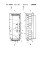
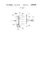
- FIG. 1 shows the apparatus in plan view
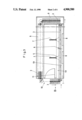
- FIG. 2 is a side elevation of the apparatus
- FIG. 3 shows the apparatus with an amended transport and storing system circuit boards to be lacquered
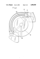
- FIG. 4 shows a curved transport rail for conducting the plates
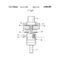
- FIG. 5 shows a head for transporting the plates in hanging position on transport means
- FIG. 6 is a diagrammatic plan view of a spraying apparatus with suctional removal box
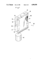
- FIG. 7 is a perspective view of the suctional removal box according to the invention for electrostatic lacquering devices.
- a substantially dust-free chamber 1 contains a first lacquering station 2 for the electrostatic lacquering of one side of printed circuit boards 3 which are moved through the chamber 1 at a uniform speed suspended vertically from an endless chain 4 or belt.
- the printed circuit board 3 disposed in the spraying position After the printed circuit board 3 disposed in the spraying position has left the spraying nozzle 5 of the first lacquering station 2, it arrives at a turning station 6, at which the printed circuit board 3 is turned - i.e., turned through 180° around a vertical axis. Then the turned-over printed circuit board 3 moves into the zone of action of a second lacquering station 7 by which the other side of the printed circuit board is coated with a lacquer film. Disposed downstream of each lacquering station 2, 7 is a suctional removal device 8 being explained in detail below.
- the printed circuit board 3 After leaving the second lacquering station 7, the printed circuit board 3, now electrostatically coated with a lacquer film on both sides, moves into a drying oven 9 which occupies the rear wall of the chamber 1 and the side opposite the lacquering stations 2, 7. Both lacquer layers on the surface of the printed circuit boards 3 are dried simultaneously in the drying oven 9.
- the chamber 1 is closed off in a substantially dust-free manner by a door 11, through which the interior of the chamber 1 is accessible.
- the printed circuit boards 3 are suspended each from a rod 12 inserted downwardly through the links of the chain 4, which are constructed in the form of hollow rivets, or the rods 12 being guided by their heads 14 in rails 13 and transported on and between two parallel arranged endless belts 4a, 4b (FIG. 3).
- Means enable the printed circuit boards 3 suspended from the rods to be turned over at the turning station 6, f.i. a lever 15 connected to the turning mechanism 16 between rod 12 and circuit board 3 which runs against a stopper 17 being arranged in the path of the level 15 in the turning station 6.
- the apparatus of FIG. 1 can also have another transport system as can be seen from FIG. 3.
- the circuit boards 3 are conveyed through the chamber 1 in a way similar to that illustrated in FIG. 1. However, when conveyed through the drying furnace, the circuit boards 3 have a position perpendicular to that shown in FIG. 1.
- the capacity of the drying furnace is greatly enlarged and the remaining time of the circuit boards 3 in the drying furnace can be extended if separate conveying means are arranged in the chamber 1 and in the drying furnace.
- the transportation speed in the drying furnace and in the spraying chamber 1 can then be different.
- circuit boards 3 to be lacquered are successively mounted to the rod 12 by means of which the circuit boards 3 are hung up in a buffer in the position B at the front of the apparatus. From this buffer the circuit boards 3 are successively pushed onto the endless chain 4 (FIG. 1) or an endless belt arrangement comprising two parallel extending endless belts 4a, 4b (FIG. 3).
- lacquer is sprayed in the direction indicated by arrow 101 from a spraying nozzles 2,7 on to the circuit boards 3 successively moved past the nozzles 2,7 in the direction indicated by arrow 110.
- the air flow (arrow 130) charged with lacquer residue droplets then passes to the metal plate 40, where it unloads the majority of such droplets. Only a very small proportion of lacquer residue then flows around the edges 50 of the metal plate 40 and passes to the filter paper 100 upstream of the perforate sheet 20 on the suction side of the suctional removal box 30 As a result, the filter paper 100 becomes clogged with lacquer residues only after a very much longer time. The majority of the lacquer residues is intercepted in the tank 80 or knocked or scratched off the metal plate 40 for further use.
- the distance A at which the metal plate 40 is disposed upstream of the filter paper 100 should be in the range of centimetres and can be about 2 to 4 cm in length.
- a closed metal plate 40 is disposed by its whole surface on the suction side of a suctional removal box 60 at a distance A upstream of a perforate plate 20 covered with filter paper 100.
- the edges 50 of the metal plate 40 are bent through 90° in the direction of the suctional removal box 30 and cover the distance A between the metal plate 40 and the suction side of the suctional removal box.
- the metal plate 40 is attached to the suctional removal box 30 by permanent magnets 60.
- the suctional removal box 30 and the metal plate 40 are disposed vertically (FIG. 7)
- the lower edge of the metal plate 40 has disposed or shaped thereon a channel 70 which intercepts the lacquer residues dripping from the metal plate 40 and conveys them to a collecting tank 80.
Abstract
Description
Claims (3)
Applications Claiming Priority (4)
| Application Number | Priority Date | Filing Date | Title |
|---|---|---|---|
| DE3735798 | 1987-10-22 | ||
| DE19873735798 DE3735798A1 (en) | 1987-10-22 | 1987-10-22 | Method and device for the electrostatic coating of electrical printed circuit boards |
| DE3821278 | 1988-06-24 | ||
| DE3821278 | 1988-06-24 |
Related Child Applications (1)
| Application Number | Title | Priority Date | Filing Date |
|---|---|---|---|
| US07/392,817 Division US4947787A (en) | 1987-10-22 | 1989-08-10 | Apparatus for the electrostatic lacquering of printing circuit boards |
Publications (1)
| Publication Number | Publication Date |
|---|---|
| US4900580A true US4900580A (en) | 1990-02-13 |
Family
ID=25861012
Family Applications (2)
| Application Number | Title | Priority Date | Filing Date |
|---|---|---|---|
| US07/260,147 Expired - Lifetime US4900580A (en) | 1987-10-22 | 1988-10-20 | Process for the electrostatic lacquering of printed circuit boards |
| US07/392,817 Expired - Lifetime US4947787A (en) | 1987-10-22 | 1989-08-10 | Apparatus for the electrostatic lacquering of printing circuit boards |
Family Applications After (1)
| Application Number | Title | Priority Date | Filing Date |
|---|---|---|---|
| US07/392,817 Expired - Lifetime US4947787A (en) | 1987-10-22 | 1989-08-10 | Apparatus for the electrostatic lacquering of printing circuit boards |
Country Status (5)
| Country | Link |
|---|---|
| US (2) | US4900580A (en) |
| JP (1) | JP2637794B2 (en) |
| FR (1) | FR2623962B1 (en) |
| GB (1) | GB2211113B (en) |
| IT (1) | IT1235042B (en) |
Cited By (4)
| Publication number | Priority date | Publication date | Assignee | Title |
|---|---|---|---|---|
| US5178910A (en) * | 1991-08-29 | 1993-01-12 | Xerox Corporation | Method of coating mesh parts |
| US5188669A (en) * | 1991-02-22 | 1993-02-23 | Nordson Corporation | Circuit board coating apparatus with inverting pallet shuttle |
| CN103108493A (en) * | 2013-02-25 | 2013-05-15 | 上海夏普电器有限公司 | Damp-proof processing method of electronic circuit board |
| CN108337808A (en) * | 2018-02-05 | 2018-07-27 | 江西景旺精密电路有限公司 | A kind of PCB anti-welding production line automatically |
Families Citing this family (10)
| Publication number | Priority date | Publication date | Assignee | Title |
|---|---|---|---|---|
| JPH02257697A (en) * | 1989-03-30 | 1990-10-18 | Trinity Ind Corp | Application of solder resist |
| JPH0770822B2 (en) * | 1989-03-30 | 1995-07-31 | トリニティ工業株式会社 | How to apply solder resist |
| US5215130A (en) * | 1989-06-30 | 1993-06-01 | Hisao Kojima | Liquid-mixture auto-applying apparatus |
| DE3937071A1 (en) * | 1989-11-07 | 1991-05-08 | Kopperschmidt Mueller & Co | DEVICE AND METHOD FOR COATING PLATE-SHAPED SUBSTRATES, LIKE CIRCUIT BOARDS |
| KR920015524A (en) * | 1991-01-08 | 1992-08-27 | 윌리엄 이. 힐러 | Method and apparatus for applying material to integrated circuit dies and lead frames to improve adhesion to molding compounds |
| US5240746A (en) * | 1991-02-25 | 1993-08-31 | Delco Electronics Corporation | System for performing related operations on workpieces |
| IT1252949B (en) * | 1991-09-30 | 1995-07-06 | Gisulfo Baccini | PROCEDURE FOR THE PROCESSING OF GREEN-TAPE TYPE CIRCUITS AND DEVICE ADOPTING THIS PROCEDURE |
| US5588996A (en) * | 1994-04-01 | 1996-12-31 | Argus International | Apparatus for spray coating flat surfaces |
| US5733376A (en) * | 1994-04-01 | 1998-03-31 | Argus International | Apparatus for spray coating opposing major surfaces of a workpiece |
| CN111715487B (en) * | 2020-06-22 | 2022-06-10 | 广德众泰科技有限公司 | Electrostatic spraying method for printed circuit board |
Citations (6)
| Publication number | Priority date | Publication date | Assignee | Title |
|---|---|---|---|---|
| US2039776A (en) * | 1929-12-12 | 1936-05-05 | Patent & Licensing Corp | Method of weatherproofing shingles or like articles |
| US2051813A (en) * | 1934-03-28 | 1936-08-25 | Bellamy Leon | Machine for coating materials |
| US2741218A (en) * | 1950-11-10 | 1956-04-10 | Ransburg Electro Coating Corp | Electrostatic coating apparatus |
| US2780565A (en) * | 1953-07-17 | 1957-02-05 | Ransburg Electro Coating Corp | Electrostatic spray coating system and method |
| US4454003A (en) * | 1983-01-06 | 1984-06-12 | Systems Engineering & Manufacturing Corp. | Printed circuit board component conveyor apparatus and process |
| US4513682A (en) * | 1982-03-24 | 1985-04-30 | Protectaire Systems Co. | Positive drive rotator |
Family Cites Families (12)
| Publication number | Priority date | Publication date | Assignee | Title |
|---|---|---|---|---|
| US2952351A (en) * | 1957-04-12 | 1960-09-13 | Ransburg Electro Coating Corp | Coating apparatus |
| CH376400A (en) * | 1962-03-30 | 1964-03-31 | Burnand S A | Process for covering a part, device for implementing the process and part covered by this process |
| US3444839A (en) * | 1965-12-27 | 1969-05-20 | Ibm | Automatic spray painting machine |
| DE2109660A1 (en) * | 1971-03-01 | 1972-09-07 | Sel | Printed circuit board with increased insulation resistance and process for its manufacture |
| US4002143A (en) * | 1975-09-08 | 1977-01-11 | Indian Head Inc. | Hot end glass container coating system |
| US4276852A (en) * | 1979-08-03 | 1981-07-07 | Adams Daisy E | Painting and misting shield |
| US4303417A (en) * | 1980-10-03 | 1981-12-01 | George Koch Sons, Inc. | Spray booth with reconditioning filter system |
| FR2523503A1 (en) * | 1982-03-16 | 1983-09-23 | Stanley Mabo | FORWARD AND LOCKING TROLLEY FOR CUTTING INSTRUMENT BLADE |
| DE3340510C2 (en) * | 1983-11-09 | 1986-10-30 | Hans-Josef 5010 Bergheim Licher | Electrostatic powder coating device |
| DE3435158C1 (en) * | 1984-09-25 | 1986-04-17 | Siemens AG, 1000 Berlin und 8000 München | Method for coating copper-clad printed circuit boards |
| DE3602350C2 (en) * | 1986-01-27 | 1994-08-18 | Weber Marianne | Process and plant for double-sided coating of plates with liquid coating material |
| DE3721404A1 (en) * | 1987-06-29 | 1989-01-12 | Kopperschmidt Mueller & Co | DEVICE FOR ELECTROSTATIC SPRAY COATING OF PLATE-SHAPED WORKPIECES |
-
1988
- 1988-10-20 US US07/260,147 patent/US4900580A/en not_active Expired - Lifetime
- 1988-10-20 FR FR8813773A patent/FR2623962B1/en not_active Expired - Fee Related
- 1988-10-21 IT IT8848481A patent/IT1235042B/en active
- 1988-10-21 GB GB8824654A patent/GB2211113B/en not_active Expired - Lifetime
- 1988-10-22 JP JP63265279A patent/JP2637794B2/en not_active Expired - Lifetime
-
1989
- 1989-08-10 US US07/392,817 patent/US4947787A/en not_active Expired - Lifetime
Patent Citations (6)
| Publication number | Priority date | Publication date | Assignee | Title |
|---|---|---|---|---|
| US2039776A (en) * | 1929-12-12 | 1936-05-05 | Patent & Licensing Corp | Method of weatherproofing shingles or like articles |
| US2051813A (en) * | 1934-03-28 | 1936-08-25 | Bellamy Leon | Machine for coating materials |
| US2741218A (en) * | 1950-11-10 | 1956-04-10 | Ransburg Electro Coating Corp | Electrostatic coating apparatus |
| US2780565A (en) * | 1953-07-17 | 1957-02-05 | Ransburg Electro Coating Corp | Electrostatic spray coating system and method |
| US4513682A (en) * | 1982-03-24 | 1985-04-30 | Protectaire Systems Co. | Positive drive rotator |
| US4454003A (en) * | 1983-01-06 | 1984-06-12 | Systems Engineering & Manufacturing Corp. | Printed circuit board component conveyor apparatus and process |
Cited By (5)
| Publication number | Priority date | Publication date | Assignee | Title |
|---|---|---|---|---|
| US5188669A (en) * | 1991-02-22 | 1993-02-23 | Nordson Corporation | Circuit board coating apparatus with inverting pallet shuttle |
| US5178910A (en) * | 1991-08-29 | 1993-01-12 | Xerox Corporation | Method of coating mesh parts |
| CN103108493A (en) * | 2013-02-25 | 2013-05-15 | 上海夏普电器有限公司 | Damp-proof processing method of electronic circuit board |
| CN103108493B (en) * | 2013-02-25 | 2016-01-20 | 上海夏普电器有限公司 | A kind of Moistureproof treatment method of electronic circuit board |
| CN108337808A (en) * | 2018-02-05 | 2018-07-27 | 江西景旺精密电路有限公司 | A kind of PCB anti-welding production line automatically |
Also Published As
| Publication number | Publication date |
|---|---|
| GB8824654D0 (en) | 1988-11-30 |
| US4947787A (en) | 1990-08-14 |
| JPH01272190A (en) | 1989-10-31 |
| FR2623962A1 (en) | 1989-06-02 |
| GB2211113B (en) | 1991-04-10 |
| JP2637794B2 (en) | 1997-08-06 |
| IT1235042B (en) | 1992-06-17 |
| IT8848481A0 (en) | 1988-10-21 |
| FR2623962B1 (en) | 1994-07-08 |
| GB2211113A (en) | 1989-06-28 |
Similar Documents
| Publication | Publication Date | Title |
|---|---|---|
| US4900580A (en) | Process for the electrostatic lacquering of printed circuit boards | |
| JPH03186371A (en) | Device and method for coating plate-like substrate such as printed board | |
| US5136973A (en) | Process and device for electrostatically spraying a liquid coating onto a substrate and for drying the liquid coating on the substrate | |
| CA2091383A1 (en) | Enclosure for painting and a method of enforcing evaporation from a coating on a panel surface | |
| EP0267910B1 (en) | Powder deposition apparatus | |
| US4427019A (en) | Chemical process apparatus | |
| JPH0445565B2 (en) | ||
| ITBO20000278A1 (en) | METHOD AND APPARATUS FOR THE HORIZONTAL PAINTING OF WOODEN OR WOOD DERIVATED ITEMS AND OF PREVALENT FLAT EXTENSION. | |
| CA2016362A1 (en) | Method and apparatus for continuously drying boards coated on both sides | |
| JPH0811224B2 (en) | Article cleaning equipment | |
| JP3238413B2 (en) | Spray coating equipment | |
| JP4021024B2 (en) | Electrostatic powder coating apparatus and method | |
| SU1120919A3 (en) | Arrangement for electrostatic spraying of coatings | |
| JP3207106B2 (en) | Coating equipment for water-soluble paint | |
| JPS6138653A (en) | Electrostatic painting booth provided with both filter band and wire-net conveyor | |
| EP0220055B1 (en) | System for spray coating substrates | |
| US4729340A (en) | Method and apparatus for powder coating elongated objects | |
| US2550657A (en) | Electrostatic coating method and apparatus | |
| JP3052011B2 (en) | Setting booth | |
| JPS63185472A (en) | Coating device | |
| DE3920615A1 (en) | PCB electrostatic lacquering appts. | |
| JPS62183874A (en) | Coating control apparatus | |
| JPH01159078A (en) | Applicator | |
| JP2993807B2 (en) | Exhaust treatment device for painting booth with air supply | |
| JPS60238176A (en) | Powder coating method and device for slender body |
Legal Events
| Date | Code | Title | Description |
|---|---|---|---|
| FEPP | Fee payment procedure |
Free format text: PAYOR NUMBER ASSIGNED (ORIGINAL EVENT CODE: ASPN); ENTITY STATUS OF PATENT OWNER: LARGE ENTITY |
|
| STCF | Information on status: patent grant |
Free format text: PATENTED CASE |
|
| FPAY | Fee payment |
Year of fee payment: 4 |
|
| SULP | Surcharge for late payment | ||
| FPAY | Fee payment |
Year of fee payment: 8 |
|
| AS | Assignment |
Owner name: MACDERMID, INCORPORATED, CONNECTICUT Free format text: ASSIGNMENT OF ASSIGNORS INTEREST;ASSIGNOR:NATIONAL STARCH AND CHEMICAL INVESTMENT HOLDING CORP.;REEL/FRAME:008761/0562 Effective date: 19970925 Owner name: MACDERMID, INCORPORATED, CONNECTICUT Free format text: ASSIGNMENT OF ASSIGNORS INTEREST;ASSIGNOR:NATIONAL STARCH AND CHEMICAL INVESTMENT HOLDING CORPORATION;REEL/FRAME:008761/0565 Effective date: 19970925 |
|
| AS | Assignment |
Owner name: MACDERMID, ACUMEN, INC., DELAWARE Free format text: ASSIGNMENT OF ASSIGNORS INTEREST;ASSIGNOR:MACDERMID, INCORPORATED;REEL/FRAME:008848/0767 Effective date: 19971111 Owner name: MACDERMID, ACUMEN, INC., DELAWARE Free format text: ASSIGNMENT OF ASSIGNORS INTEREST;ASSIGNOR:MACDERMID, INCORPORATED;REEL/FRAME:008848/0776 Effective date: 19971111 |
|
| FEPP | Fee payment procedure |
Free format text: PAYER NUMBER DE-ASSIGNED (ORIGINAL EVENT CODE: RMPN); ENTITY STATUS OF PATENT OWNER: LARGE ENTITY Free format text: PAYOR NUMBER ASSIGNED (ORIGINAL EVENT CODE: ASPN); ENTITY STATUS OF PATENT OWNER: LARGE ENTITY |
|
| FPAY | Fee payment |
Year of fee payment: 12 |
|
| AS | Assignment |
Owner name: CREDIT SUISSE, CAYMAN ISLANDS BRANCH, AS COLLATERA Free format text: SECURITY AGREEMENT;ASSIGNOR:MACDERMID ACUMEN, INC.;REEL/FRAME:020004/0936 Effective date: 20070412 |
|
| AS | Assignment |
Owner name: MACDERMID ACUMEN, INC., CONNECTICUT Free format text: RELEASE OF SECURITY INTEREST IN PATENT COLLATERAL AT REEL/FRAME NO. 20004/0936;ASSIGNOR:CREDIT SUISSE AG, CAYMAN ISLANDS BRANCH;REEL/FRAME:030704/0316 Effective date: 20130607 |