US4901085A - Divided LLBFN/HMPA transmitted architecture - Google Patents
Divided LLBFN/HMPA transmitted architecture Download PDFInfo
- Publication number
- US4901085A US4901085A US07/248,190 US24819088A US4901085A US 4901085 A US4901085 A US 4901085A US 24819088 A US24819088 A US 24819088A US 4901085 A US4901085 A US 4901085A
- Authority
- US
- United States
- Prior art keywords
- hmpa
- power
- amplifiers
- hybrid matrix
- beams
- Prior art date
- Legal status (The legal status is an assumption and is not a legal conclusion. Google has not performed a legal analysis and makes no representation as to the accuracy of the status listed.)
- Expired - Lifetime
Links
Images

Classifications
-
- H—ELECTRICITY
- H01—ELECTRIC ELEMENTS
- H01Q—ANTENNAS, i.e. RADIO AERIALS
- H01Q3/00—Arrangements for changing or varying the orientation or the shape of the directional pattern of the waves radiated from an antenna or antenna system
- H01Q3/26—Arrangements for changing or varying the orientation or the shape of the directional pattern of the waves radiated from an antenna or antenna system varying the relative phase or relative amplitude of energisation between two or more active radiating elements; varying the distribution of energy across a radiating aperture
- H01Q3/30—Arrangements for changing or varying the orientation or the shape of the directional pattern of the waves radiated from an antenna or antenna system varying the relative phase or relative amplitude of energisation between two or more active radiating elements; varying the distribution of energy across a radiating aperture varying the relative phase between the radiating elements of an array
- H01Q3/34—Arrangements for changing or varying the orientation or the shape of the directional pattern of the waves radiated from an antenna or antenna system varying the relative phase or relative amplitude of energisation between two or more active radiating elements; varying the distribution of energy across a radiating aperture varying the relative phase between the radiating elements of an array by electrical means
- H01Q3/40—Arrangements for changing or varying the orientation or the shape of the directional pattern of the waves radiated from an antenna or antenna system varying the relative phase or relative amplitude of energisation between two or more active radiating elements; varying the distribution of energy across a radiating aperture varying the relative phase between the radiating elements of an array by electrical means with phasing matrix
-
- H—ELECTRICITY
- H04—ELECTRIC COMMUNICATION TECHNIQUE
- H04B—TRANSMISSION
- H04B7/00—Radio transmission systems, i.e. using radiation field
- H04B7/14—Relay systems
- H04B7/15—Active relay systems
- H04B7/185—Space-based or airborne stations; Stations for satellite systems
- H04B7/1851—Systems using a satellite or space-based relay
- H04B7/18515—Transmission equipment in satellites or space-based relays
Definitions
- This invention relates to satellite communications and, more particularly, to an improved transmitter section of a communications satellite.
- MBA multibeam antenna
- HMPA Hybrid Matrix Power Amplifier
- beams may be formed from multiple feed elements.
- An example of such a system is described in copending U.S. patent application Ser. No. 197,328 filed on May 28, 1988 and assigned to the assignee of the present application.
- the disclosure of U.S. patent application Ser. No. 197,328 is hereby incorporated by reference.
- the system described in that application combines the capabilities of a low level beam forming network (LLBFN) with the hybrid matrix power amplifier (HMPA).
- LLBFN low level beam forming network
- HMPA hybrid matrix power amplifier
- the LLBFN allows efficient beam overlap using multiple element feed clusters where adjacent beams share feed elements.
- the HMPA allows the power for any feed element or set of feed elements to be distributed evenly among the individual power amplifiers providing flexible assignment of traffic between beams up to the limit of the spacecraft power resources.
- the present invention relates to an improvement on the combination of the LLBFN and the HMPA through the inherent power division within the LLBFN. This improvement:
- the single HMPA used in the above-identified prior application is replaced with a plurality of smaller, preferably identical, HMPA's.
- HMPA's a plurality of smaller, preferably identical, HMPA's.
- ideal results are achieved when the number of HMPA's is equal to the number of radiating elements used to form each beam but useful results can also be obtained when the number of HMPA's is greater or less than the number of radiating elements used to form each beam.
- the configuration of the feed array and the type of excitation of the elements of the feed array determine the number of HMPA's which are most appropriate.
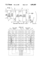
- FIG. 1 illustrates schematically the system described in the above-identified prior application.
- FIG. 2 illustrates schematically an HMPA with up to 16 input and 16 output ports, i.e., a 16x16 HMPA.
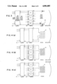
- FIG. 3 illustrates schematically the general concept of the present invention.
- FIGS. 4a, b and c illustrate schematically the present invention as applied to a 4 ⁇ 3 rectangular feed antenna, with FIG. 4a showing the case where a single HMPA is used, FIG. 4b showing the case where three HMPA's are used and FIG. 4c showing the case where four HMPA's are used.
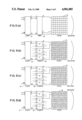
- FIGS. 5a, b, c and d illustrate schematically the present invention as applied to a 9 ⁇ 8 rectangular feed antenna, with FIG. 5a showing the case where a single HMPA is used, FIG. 5b showing the case where five HMPA's are used, FIG. 5c showing the case where eight HMPA's are used and FIG. 5d showing the case where nine HMPA's are used.
- FIGS. 6a, b, c and d illustrate schematically the present invention as applied to a 91 element hexagonal feed antenna, with FIG. 6a showing the case where a single HMPA is used, FIG. 6b showing the case where four HMPA's are used, FIG. 6c showing the case where six HMPA's are used and FIG. 6d showing the case where seven HMPA's are used.
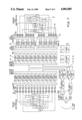
- FIG. 7 illustrates schematically one practical embodiment of the invention using 14 antenna horns.
- an LLBFN 10 has a plurality of input ports 12 equal in number to the number of beams and a plurality of output ports 14 equal in number to the number of radiating elements 16.
- the output ports are connected to respective input ports 18 of an HMPA 20 the corresponding output ports 22 of which are connected respectively to the radiating elements 16 via filter circuits 24.
- the HMPA 20 consists of a 2 n ⁇ 2 n low power input hybrid matrix 26, a 2 n ⁇ 2 n high power output hybrid matrix 28, and a full complement of 2 n individual power amplifiers 30 in between. Details of an HMPA with up to 16 ports HMPA are shown in FIG. 2. There is a one to one correspondence between the input and output ports of the HMPA so that a signal applied to a single input port (i.e., the i th input port) appears in amplified form at a single output port (i.e., the i th output port). The signal levels at the respective inputs to all of the individual amplifiers are equal so that all of the amplifiers are driven at the same level. Some of the output ports may be terminated, if required, provided the corresponding input ports are also terminated. All amplifiers, however, must be present so that the required number of amplifiers is between one and two times the total number of feed elements.
- the formation of beams by multiple element feeds requires that the LLBFN apply coherent signals to multiple input ports of the HMPA.
- the HMPA ports used to form each individual beam therefore, must be selected so that the resulting power distribution arising from that beam is uniform or near uniform among the individual amplifiers.
- the difficulty in obtaining at least a near uniform power distribution increases with the number of beams and the number of feed elements forming each beam. How this is achieved is discussed in the above-identified prior application.
- HMPA high power equipment
- Spacecraft typically have two separated thermal radiating faces (i.e., the north and south faces for a geosynchronous spacecraft). Payload high power equipment is divided more or less equally between these two faces. For a payload dominated by a single transmit antenna, it would be required to mount half the amplifiers on each of the thermal radiating faces, thereby complicating the layout of the high power output matrix.
- the single HMPA has the ability to apply all of the power to a single radiating element while distributing the power equally among all of the amplifiers. This capability is not required when each beam is formed by means of a cluster of feed elements.
- the HMPA is required at most to apply all of the power to a single beam while distributing the power from that single beam equally or near equally among the amplifiers. With this more appropriate requirement, the HMPA may be subdivided into a number of smaller HMPA's 20' (see FIG. 3). These smaller HMPA's require fewer levels of hybrids and thus will have a lower total mass as well as lower insertion loss. The approach also allows more flexibility in choice of total number of amplifiers (m.2 n rather than 2 n ) so that, if fewer amplifiers are employed, a potential mass saving results.
- the basis for this subdivision lies in the inherent division of power in the LLBFN between the multiple elements forming each beam and, for the non ideal case, in the statistical distribution of power among the beams. If the LLBFN divides the power equally between each of the smaller HMPA's, then there is a uniform distribution of power among the amplifiers no matter how power is assigned to the beams. This occurs, for example, when the number of smaller HMPA's is equal to the number of elements used to form each beam and there is uniform excitation of the elements for each beam. Even if the LLBFN does not divide the power for each individual beam, however, random distribution of power between the beams will dictate near equal power among the amplifiers.
- HMPA If the number of HMPA's is less than the number of elements used to form each beam, then at least one HMPA must be used to drive two or more elements forming the beam. In this case, the HMPA ports used to drive these two or more elements (as well as similar elements of other beams) must be selected so that the resulting power distribution arising from that beam is uniform or near uniform among the individual amplifiers of that HMPA. This, however, is a much simpler task than the selection of ports for a large single HMPA.
- each HMPA is designated by a letter "A”, “B", “C” and, in the case of FIG. 4c, "D" and the radiating elements are also designated A, B, C and (for FIG. 4c) D.
- the radiating elements A are fed by HMPA "A”, radiating elements B fed by HMPA "B” and so on.
- the use of four HMPA's provides equivalent performance to the use of a single HMPA (FIG.
- HMPA's reduces the number of amplifiers to just 12.
- the number of HMPA's is less than the number of elements per beam, for each beam one of the HMPA's must drive two elements. This implies selection of HMPA ports to maximize the uniformity of amplifier power loading. With uniform excitation of the four elements forming each beam there will not be uniform amplifier loading for the individual beam. This antenna has only six beams so that random assignment of power between the beams will not provide a high probability of near equal amplifier loading.
- HMPA's For this antenna configuration, the use of four HMPA's would appear to be the better choice unless there were some special circumstances implicating the use of only three HMPA's. This may include:
- HMPA For a more complex 9 ⁇ 8 element rectangular feed antenna where there are fifty six beams and each beam is formed by nine elements, several possible HMPA divisions are given in Table 2.
- the use of eight HMPA's (FIG. 5c) provides equal performance to the use of a single HMPA (FIG. 5a) but requires fewer hybrids and minimizes the problem of HMPA port selection.
- the use of two of four HMPA's has similar though less substantial advantages. There is a requirement for 128 amplifiers for all of these systems and each would accommodate a 16 ⁇ 8 element rectangular feed with no change in HMPA hardware.
- HMPA's reduces the number of amplifiers to just 80. However, since the number of HMPA's is less than the number of elements per beam, each HMPA must drive two elements for a number of beams. This implies selection of HMPA ports to maximize the uniformity of amplifier loading. Again, unless the power distribution between the nine elements forming each beam is skewed, there will not be equal amplifier loading for each beam.
- the use of 10 HMPA's also reduces the number of amplifiers to just 80 and avoids the requirement for selection of HMPA beam ports while providing near uniform amplifier loading. Even with non-uniform amplifier loading for each beam, since this antenna has 56 beams, random assignment of power between the beams will provide a high probability of near equal amplifier loading.
- HMPA For a more complex 91 element hexagonal feed antenna where there are sixty one beams and each beam is formed by seven elements, a number of possible HMPA divisions are given in Table 3.
- the use of eight HMPA's would provide the same performance as the use of a single HMPA (FIG. 6a) but would require fewer hybrids and would also minimize the problem of HMPA port selection.
- the use of two or four HMPA's (FIG. 6b) has similar though less substantial advantages except that HMPA ports must still be selected. There is a requirement for 128 amplifiers for all of these systems and each would accommodate a 127 element hexagonal feed antenna with no change in HMPA hardware.
- HMPA's reduces the number of amplifiers to just 96.
- the number of HMPA's is less than the number of elements per beam, one HMPA must drive two elements for each beam. This implies selection of HMPA ports and, unless the power distribution between the nine elements forming each beam is skewed, there will not be equal sharing of power among the amplifiers.
- this antenna has 61 beams so that random assignment of power between the beams will provide a high probability of near equal amplifiers loading.
- HMPA HMPA's
- 112 amplifiers are required.
- amplifier loading will be uniform without the need for HMPA beam ports selection.
- the six and seven HMPA systems are the clear favourites. The seven HMPA system is simpler and provides uniform amplifier loading while the six HMPA system, which employs fewer amplifiers, will not necessarily provide totally uniform amplifier loading and requires HMPA port selection.
- the best option is to have the same number of HMPA's as there are feed elements used to form a beam so as to avoid the requirement for port selection.
- the beam power is equally divided among the feed elements in a cluster, then the power division among the amplifiers is exact. This is not generally the case and so equal power division is more a matter of statistical averaging among the HMPA along with a judicious selection of ports.
- FIG. 7 this illustrates the invention as applied to an MSAT L-band transmitter.
- the left hand side of the figure is the RECEIVE side which is conventional and will not be described hereinafter.
- the right hand side is the TRANSMIT side and includes an antenna array of fourteen horns 34. Each horn 34 is connected through an output filter 36 to a respective output port 38 of two 8 ⁇ 8 HMPA's reference HMPA "A” and HMPA "B", with one output port of each HMPA being terminated.
- the amplifiers 40 within the HMPA's are solid state power amplifiers (SSPA) grouped in pairs with a 3 for 2 redundancy plus cross-strapping between pairs.
- SSPA solid state power amplifiers
- Beams are formed using three or four horns per beam. For example, one beam is formed by horn numbers 9, 10 and 11 whereas another beam is formed by horn numbers 6, 8, 9 and 10. Because there are more horns per beam than there are HMPA's, the HMPA ports used for each horn must be carefully selected to provide uniform (or near uniform) amplifier loading for each beam within each HMPA.
- Power for each beam need not be distributed uniformly among the 3 or 4 horns nor necessarily between the two HMPA's. This means that for a number of the beams the amplifiers will not be uniformly loaded. However, for all of these beams the amplifier loading is reasonably even. Distribution of traffic between the beams will result in near uniform loading.
- the LLBFN 42 and FILTER/SWITCH MATRIX 44 are conventional and will not, therefore, be described further.
- HMPA subdividion can provide equilvalent power sharing performance compared to the use of a single large HMPA. Subdivision also reduces the number of hybrid levels thus decreasing the mass while also reducing the insertion of loss. In many instances it can also reduce the number of amplifiers and thus again reduce the mass. Most importantly, however, HMPA subdivision:
- HMPA's it may be advantageous to use different sizes in order to reduce the number of amplifiers despite uneven loading. For instance, a system with 60 feed elements could be driven by seven 8 ⁇ 8 and one 4 ⁇ 4 HMPA's.
Abstract
Description
                                  TABLE 1
__________________________________________________________________________
Concepts for a 4 by 3 Rectangular Feed Antenna
(4 elements per beam, 6 beams)
HMPA's  Port
            Amplifiers FIG.
No.
   Size Sel.
            No.
               Uniform Load
                       No. Notes
__________________________________________________________________________
0       N/A 12 No           Only marginal
                           power sharing.
1  16 × 16
        4   16 Yes     4a  Port selection
                           difficult.
2  8 × 8
        2   16 Yes         Uniform with
                           equal excitation
3  4 × 4
        2   12 Possible
                       4b  Uniform if
                           excitation
                           skewed.
                           Statistics do
                           not help.
4  4 × 4
        none
            16 Yes     4c  Uniform with
                           equal excitation
8  2 × 2
        none
            16 No          Some improve-
                           ment over no
                           HMPA.
__________________________________________________________________________
                                  TABLE 2
__________________________________________________________________________
Concepts for a 9 by 8 Feed Antenna
(9 elements per beam, 56 beams)
HMPA's   Port
            Amplifiers  FIG.
No.
   Size  Sel.
            No.
               Uniform Load
                        No.
                           Notes
__________________________________________________________________________
0        N/A
            72 No           Only marginal
                           power sharing.
1  128 × 128
         9  128
               Yes      5a Port selection
                           difficult.
3  32 × 32
         3  96 Near        Port selection
                           manageable.
5  16 × 16
         2  80 Near     5b Uniform is
                           excitation
                           skewed.
8  16 × 16
         2  128
               Near     5c
4  32 × 32
         3  128
               Near        Port selection
                           manageable
2  64 × 64
         5  128
               Near        Port selection
                           difficult.
9  8 × 8
         none
            72 Yes      5d Uniform if
                           equal excitation
10 8 × 8
         none
            80 Near
__________________________________________________________________________
                                  TABLE 3
__________________________________________________________________________
Concepts for a 91 Element Hexagonal Feed
Antenna
(7 Elements per beam, 61 beams)
HMPA's   Port
            Amplifiers  FIG.
No.
   Size  Sel.
            No.
               Uniform Load
                        No.
                           Notes
__________________________________________________________________________
0        N/A
            72 No           Only marginal
                           power sharing.
1  128 × 128
         7  128
               Yes      6a Port Selection
                           Difficult.
2  64 × 64
         4  128
               Near        Port Selection
                           Difficult.
4  32 × 32
         2  128
               Near     6b Uniform if
                           excitation skewed.
6  16 × 16
         2  96 Near     6c statistics make
3  32 × 32
         3  96 Near        uniform
7  16 × 16
         none
            112
               Yes      6d Uniform if
                           excitation equal
8  16 × 16
         none
            128
               Near
__________________________________________________________________________
Claims (3)
Priority Applications (1)
| Application Number | Priority Date | Filing Date | Title |
|---|---|---|---|
| US07/248,190 US4901085A (en) | 1988-09-23 | 1988-09-23 | Divided LLBFN/HMPA transmitted architecture |
Applications Claiming Priority (1)
| Application Number | Priority Date | Filing Date | Title |
|---|---|---|---|
| US07/248,190 US4901085A (en) | 1988-09-23 | 1988-09-23 | Divided LLBFN/HMPA transmitted architecture |
Publications (1)
| Publication Number | Publication Date |
|---|---|
| US4901085A true US4901085A (en) | 1990-02-13 |
Family
ID=22938076
Family Applications (1)
| Application Number | Title | Priority Date | Filing Date |
|---|---|---|---|
| US07/248,190 Expired - Lifetime US4901085A (en) | 1988-09-23 | 1988-09-23 | Divided LLBFN/HMPA transmitted architecture |
Country Status (1)
| Country | Link |
|---|---|
| US (1) | US4901085A (en) |
Cited By (39)
| Publication number | Priority date | Publication date | Assignee | Title |
|---|---|---|---|---|
| US5025485A (en) * | 1989-01-12 | 1991-06-18 | General Electric Company | Multi-feed, multi-channel communication system |
| US5033108A (en) * | 1988-08-17 | 1991-07-16 | British Aerospace Public Limited Company Limited | Signal repeater using shared amplification with selectable input/output connections |
| EP0480341A1 (en) * | 1990-10-09 | 1992-04-15 | Hughes Aircraft Company | Hybrid matrix amplifier systems, and methods for making thermally-balanced hybrid matrix amplifier systems |
| US5115248A (en) * | 1989-09-26 | 1992-05-19 | Agence Spatiale Europeenne | Multibeam antenna feed device |
| EP0497652A1 (en) * | 1991-01-31 | 1992-08-05 | Agence Spatiale Europeenne | Device for the electronic control of the radiation pattern of a single or multi beam antenna with variable direction and/or width |
| US5287543A (en) * | 1991-10-07 | 1994-02-15 | General Electric Co. | Multichannel communication system with an amplifier in each channel |
| US5289193A (en) * | 1990-11-29 | 1994-02-22 | Alcatel Espace | Reconfigurable transmission antenna |
| US5428814A (en) * | 1992-08-14 | 1995-06-27 | Alcatel Espace | Space communications apparatus employing switchable band filters for transparently switching signals on board a communications satellite, payload architectures using such apparatus, and methods of implementing the apparatus and the architectures |
| WO1995019066A1 (en) * | 1994-01-11 | 1995-07-13 | Ericsson Ge Mobile Communications Inc. | Waste energy control management for power amplifier |
| GB2288913A (en) * | 1994-04-18 | 1995-11-01 | Int Maritime Satellite Organiz | Antenna |
| EP0683541A1 (en) * | 1994-05-17 | 1995-11-22 | SPACE ENGINEERING S.p.A. | Shaped-beam or scanned beams reflector or lens antenna |
| US5646631A (en) * | 1995-12-15 | 1997-07-08 | Lucent Technologies Inc. | Peak power reduction in power sharing amplifier networks |
| US5734345A (en) * | 1996-04-23 | 1998-03-31 | Trw Inc. | Antenna system for controlling and redirecting communications beams |
| WO1998027645A1 (en) * | 1996-12-16 | 1998-06-25 | Ericsson Inc. | Intermodulation compensation in multi-channel amplifiers |
| US5812088A (en) * | 1994-12-19 | 1998-09-22 | Agence Spatiale Europeenne | Beam forming network for radiofrequency antennas |
| US5818388A (en) * | 1996-06-06 | 1998-10-06 | Hughes Electronics Corporation | Satellite communications apparatus using active redundancy |
| US5825762A (en) * | 1996-09-24 | 1998-10-20 | Motorola, Inc. | Apparatus and methods for providing wireless communication to a sectorized coverage area |
| EP0963005A2 (en) * | 1998-06-05 | 1999-12-08 | Hughes Electronics Corporation | Reconfigurable multiple beam satellite reflector antenna with an array feed |
| US6104935A (en) * | 1997-05-05 | 2000-08-15 | Nortel Networks Corporation | Down link beam forming architecture for heavily overlapped beam configuration |
| EP1050926A2 (en) * | 1999-05-04 | 2000-11-08 | Hughes Electronics Corporation | Hybridized space/ground beam forming |
| US6175719B1 (en) * | 1997-06-25 | 2001-01-16 | Hughes Electronics Corporation | Multi-spot-beam satellite system with broadcast and surge capacity capability |
| US6243038B1 (en) * | 1998-12-17 | 2001-06-05 | Metawave Communications Corporation | System and method providing amplification of narrow band signals with multi-channel amplifiers |
| US6437738B1 (en) * | 2001-02-12 | 2002-08-20 | Us Commerce | Hexagonal-annulus phased array antenna for radar wind profiling on moving platforms |
| US6452491B1 (en) | 2001-04-25 | 2002-09-17 | Simplexgrinnell Lp | Amplifier and heat sink configuration |
| US6553012B1 (en) * | 1997-02-13 | 2003-04-22 | Nokia Telecommunications Oy | Method and apparatus for directional radio communication |
| US20030096573A1 (en) * | 2001-11-20 | 2003-05-22 | Nuber Raymond M. | Forward and return direction payload architecture using equivalent and shared components and subassemblies |
| US6650281B2 (en) * | 2000-07-06 | 2003-11-18 | Alcatel | Telecommunications antenna intended to cover a large terrestrial area |
| US6670918B2 (en) * | 2001-06-21 | 2003-12-30 | Alcatel | Method of repointing a reflector array antenna |
| US20070281612A1 (en) * | 2006-05-30 | 2007-12-06 | Atc Technologies Llc | Methods and Systems for Satellite Communications Employing Ground-Based Beam Forming with Spatially Distributed Hybrid Matrix Amplifiers |
| CN102556368A (en) * | 2010-12-07 | 2012-07-11 | 波音公司 | Power management scheme for protecting components on board a spacecraft |
| US9184498B2 (en) | 2013-03-15 | 2015-11-10 | Gigoptix, Inc. | Extending beamforming capability of a coupled voltage controlled oscillator (VCO) array during local oscillator (LO) signal generation through fine control of a tunable frequency of a tank circuit of a VCO thereof |
| US9275690B2 (en) | 2012-05-30 | 2016-03-01 | Tahoe Rf Semiconductor, Inc. | Power management in an electronic system through reducing energy usage of a battery and/or controlling an output power of an amplifier thereof |
| US9509351B2 (en) | 2012-07-27 | 2016-11-29 | Tahoe Rf Semiconductor, Inc. | Simultaneous accommodation of a low power signal and an interfering signal in a radio frequency (RF) receiver |
| US9531070B2 (en) | 2013-03-15 | 2016-12-27 | Christopher T. Schiller | Extending beamforming capability of a coupled voltage controlled oscillator (VCO) array during local oscillator (LO) signal generation through accommodating differential coupling between VCOs thereof |
| US9666942B2 (en) | 2013-03-15 | 2017-05-30 | Gigpeak, Inc. | Adaptive transmit array for beam-steering |
| US9716315B2 (en) | 2013-03-15 | 2017-07-25 | Gigpeak, Inc. | Automatic high-resolution adaptive beam-steering |
| US9722310B2 (en) | 2013-03-15 | 2017-08-01 | Gigpeak, Inc. | Extending beamforming capability of a coupled voltage controlled oscillator (VCO) array during local oscillator (LO) signal generation through frequency multiplication |
| US9780449B2 (en) | 2013-03-15 | 2017-10-03 | Integrated Device Technology, Inc. | Phase shift based improved reference input frequency signal injection into a coupled voltage controlled oscillator (VCO) array during local oscillator (LO) signal generation to reduce a phase-steering requirement during beamforming |
| US9837714B2 (en) | 2013-03-15 | 2017-12-05 | Integrated Device Technology, Inc. | Extending beamforming capability of a coupled voltage controlled oscillator (VCO) array during local oscillator (LO) signal generation through a circular configuration thereof |
Citations (6)
| Publication number | Priority date | Publication date | Assignee | Title |
|---|---|---|---|---|
| US4414550A (en) * | 1981-08-04 | 1983-11-08 | The Bendix Corporation | Low profile circular array antenna and microstrip elements therefor |
| US4499471A (en) * | 1983-05-02 | 1985-02-12 | Ford Aerospace & Communications Corporation | Reconfigurable dual mode network |
| US4633259A (en) * | 1984-07-10 | 1986-12-30 | Westinghouse Electric Corp. | Lossless orthogonal beam forming network |
| US4638317A (en) * | 1984-06-19 | 1987-01-20 | Westinghouse Electric Corp. | Orthogonal beam forming network |
| US4652379A (en) * | 1978-09-05 | 1987-03-24 | Ture Hultman | Filtering impurities from liquid using mineral wool fiber material |
| US4727421A (en) * | 1984-10-04 | 1988-02-23 | Nec Corporation | Method of coding picture signal and picture coding/decoding apparatus utilizing the same |
-
1988
- 1988-09-23 US US07/248,190 patent/US4901085A/en not_active Expired - Lifetime
Patent Citations (6)
| Publication number | Priority date | Publication date | Assignee | Title |
|---|---|---|---|---|
| US4652379A (en) * | 1978-09-05 | 1987-03-24 | Ture Hultman | Filtering impurities from liquid using mineral wool fiber material |
| US4414550A (en) * | 1981-08-04 | 1983-11-08 | The Bendix Corporation | Low profile circular array antenna and microstrip elements therefor |
| US4499471A (en) * | 1983-05-02 | 1985-02-12 | Ford Aerospace & Communications Corporation | Reconfigurable dual mode network |
| US4638317A (en) * | 1984-06-19 | 1987-01-20 | Westinghouse Electric Corp. | Orthogonal beam forming network |
| US4633259A (en) * | 1984-07-10 | 1986-12-30 | Westinghouse Electric Corp. | Lossless orthogonal beam forming network |
| US4727421A (en) * | 1984-10-04 | 1988-02-23 | Nec Corporation | Method of coding picture signal and picture coding/decoding apparatus utilizing the same |
Non-Patent Citations (2)
| Title |
|---|
| Shunichiro Egami and Makoto Kawai, "An Adaptive Multiple Beam System Concept", May 1987, vol. SAC-4, No. 5, IEEE Journal On Selected Areas of Communications. |
| Shunichiro Egami and Makoto Kawai, An Adaptive Multiple Beam System Concept , May 1987, vol. SAC 4, No. 5, IEEE Journal On Selected Areas of Communications. * |
Cited By (70)
| Publication number | Priority date | Publication date | Assignee | Title |
|---|---|---|---|---|
| US5033108A (en) * | 1988-08-17 | 1991-07-16 | British Aerospace Public Limited Company Limited | Signal repeater using shared amplification with selectable input/output connections |
| US5025485A (en) * | 1989-01-12 | 1991-06-18 | General Electric Company | Multi-feed, multi-channel communication system |
| US5115248A (en) * | 1989-09-26 | 1992-05-19 | Agence Spatiale Europeenne | Multibeam antenna feed device |
| EP0480341A1 (en) * | 1990-10-09 | 1992-04-15 | Hughes Aircraft Company | Hybrid matrix amplifier systems, and methods for making thermally-balanced hybrid matrix amplifier systems |
| US5289193A (en) * | 1990-11-29 | 1994-02-22 | Alcatel Espace | Reconfigurable transmission antenna |
| EP0497652A1 (en) * | 1991-01-31 | 1992-08-05 | Agence Spatiale Europeenne | Device for the electronic control of the radiation pattern of a single or multi beam antenna with variable direction and/or width |
| FR2672436A1 (en) * | 1991-01-31 | 1992-08-07 | Europ Agence Spatiale | DEVICE FOR ELECTRONICALLY CONTROLLING THE RADIATION DIAGRAM OF AN ANTENNA WITH ONE OR MORE DIRECTION BEAMS AND / OR VARIABLE WIDTH. |
| US5151706A (en) * | 1991-01-31 | 1992-09-29 | Agence Spatiale Europeene | Apparatus for electronically controlling the radiation pattern of an antenna having one or more beams of variable width and/or direction |
| US5287543A (en) * | 1991-10-07 | 1994-02-15 | General Electric Co. | Multichannel communication system with an amplifier in each channel |
| US5428814A (en) * | 1992-08-14 | 1995-06-27 | Alcatel Espace | Space communications apparatus employing switchable band filters for transparently switching signals on board a communications satellite, payload architectures using such apparatus, and methods of implementing the apparatus and the architectures |
| WO1995019066A1 (en) * | 1994-01-11 | 1995-07-13 | Ericsson Ge Mobile Communications Inc. | Waste energy control management for power amplifier |
| US5771444A (en) * | 1994-01-11 | 1998-06-23 | Ericsson Inc. | Waste energy control and management in power amplifiers |
| GB2290669B (en) * | 1994-01-11 | 1999-06-23 | Ericsson Ge Mobile Communicat | Waste energy control management for power amplifier |
| GB2290669A (en) * | 1994-01-11 | 1996-01-03 | Ericsson Ge Mobile Communicat | Waste energy control management for power amplifier |
| US5568088A (en) * | 1994-01-11 | 1996-10-22 | Ericsson Ge Mobile Communications Inc. | Waste energy control and management in power amplifier |
| US5574967A (en) * | 1994-01-11 | 1996-11-12 | Ericsson Ge Mobile Communications, Inc. | Waste energy control and management in power amplifiers |
| US5631604A (en) * | 1994-01-11 | 1997-05-20 | Ericsson Inc. | Waste energy control and management in power amplifiers |
| US5638024A (en) * | 1994-01-11 | 1997-06-10 | Ericsson Inc. | Waste energy control and management in power amplifiers |
| US5842140A (en) * | 1994-01-11 | 1998-11-24 | Ericsson Inc. | Waste energy control and management in power amplifiers |
| US5732325A (en) * | 1994-01-11 | 1998-03-24 | Ericsson Inc. | Waste energy control and management in power amplifiers |
| US5818298A (en) * | 1994-01-11 | 1998-10-06 | Ericsson Inc. | Linear amplifying apparatus using coupled non-linear amplifiers |
| GB2324912A (en) * | 1994-04-18 | 1998-11-04 | Int Mobile Satellite Org | Beam forming network |
| US6340948B1 (en) * | 1994-04-18 | 2002-01-22 | International Mobile Satellite Organization | Antenna system |
| GB2288913A (en) * | 1994-04-18 | 1995-11-01 | Int Maritime Satellite Organiz | Antenna |
| GB2288913B (en) * | 1994-04-18 | 1999-02-24 | Int Maritime Satellite Organiz | Satellite payload apparatus with beamformer |
| GB2324912B (en) * | 1994-04-18 | 1999-02-24 | Int Mobile Satellite Org | Beam-forming network |
| EP0683541A1 (en) * | 1994-05-17 | 1995-11-22 | SPACE ENGINEERING S.p.A. | Shaped-beam or scanned beams reflector or lens antenna |
| US5812088A (en) * | 1994-12-19 | 1998-09-22 | Agence Spatiale Europeenne | Beam forming network for radiofrequency antennas |
| US5646631A (en) * | 1995-12-15 | 1997-07-08 | Lucent Technologies Inc. | Peak power reduction in power sharing amplifier networks |
| US5734345A (en) * | 1996-04-23 | 1998-03-31 | Trw Inc. | Antenna system for controlling and redirecting communications beams |
| US5818388A (en) * | 1996-06-06 | 1998-10-06 | Hughes Electronics Corporation | Satellite communications apparatus using active redundancy |
| US5825762A (en) * | 1996-09-24 | 1998-10-20 | Motorola, Inc. | Apparatus and methods for providing wireless communication to a sectorized coverage area |
| US5933766A (en) * | 1996-12-16 | 1999-08-03 | Ericsson Inc. | Intermodulation compensation in multi-channel amplifiers |
| US6233436B1 (en) | 1996-12-16 | 2001-05-15 | Ericsson Inc. | Intermodulation compensation in multi-channel amplifiers |
| WO1998027645A1 (en) * | 1996-12-16 | 1998-06-25 | Ericsson Inc. | Intermodulation compensation in multi-channel amplifiers |
| AU732127B2 (en) * | 1996-12-16 | 2001-04-12 | Ericsson Inc. | Intermodulation compensation in multi-channel amplifiers |
| US6643526B1 (en) | 1997-02-13 | 2003-11-04 | Nokia Telecommunications Oy | Method and apparatus for directional radio communication |
| US6553012B1 (en) * | 1997-02-13 | 2003-04-22 | Nokia Telecommunications Oy | Method and apparatus for directional radio communication |
| US6104935A (en) * | 1997-05-05 | 2000-08-15 | Nortel Networks Corporation | Down link beam forming architecture for heavily overlapped beam configuration |
| US20040092227A1 (en) * | 1997-06-25 | 2004-05-13 | Hughes Electronics Corporation | Multi-spot-beam satellite system with broadcast and surge capacity capability |
| US6704544B1 (en) | 1997-06-25 | 2004-03-09 | Hughes Electronics Corporation | Multi-spot-beam satellite system with broadcast and surge capacity capability |
| US7925208B2 (en) | 1997-06-25 | 2011-04-12 | The Directv Group, Inc. | Multi-spot-beam satellite system with broadcast and surge capacity capability |
| US6175719B1 (en) * | 1997-06-25 | 2001-01-16 | Hughes Electronics Corporation | Multi-spot-beam satellite system with broadcast and surge capacity capability |
| EP0963005A3 (en) * | 1998-06-05 | 2001-03-28 | Hughes Electronics Corporation | Reconfigurable multiple beam satellite reflector antenna with an array feed |
| EP0963005A2 (en) * | 1998-06-05 | 1999-12-08 | Hughes Electronics Corporation | Reconfigurable multiple beam satellite reflector antenna with an array feed |
| US6243038B1 (en) * | 1998-12-17 | 2001-06-05 | Metawave Communications Corporation | System and method providing amplification of narrow band signals with multi-channel amplifiers |
| EP1050926A3 (en) * | 1999-05-04 | 2002-07-31 | Hughes Electronics Corporation | Hybridized space/ground beam forming |
| US6571081B1 (en) | 1999-05-04 | 2003-05-27 | Hughes Electronics Corporation | Hybridized space/ground beam forming |
| EP1050926A2 (en) * | 1999-05-04 | 2000-11-08 | Hughes Electronics Corporation | Hybridized space/ground beam forming |
| US6650281B2 (en) * | 2000-07-06 | 2003-11-18 | Alcatel | Telecommunications antenna intended to cover a large terrestrial area |
| US6437738B1 (en) * | 2001-02-12 | 2002-08-20 | Us Commerce | Hexagonal-annulus phased array antenna for radar wind profiling on moving platforms |
| US6452491B1 (en) | 2001-04-25 | 2002-09-17 | Simplexgrinnell Lp | Amplifier and heat sink configuration |
| US6670918B2 (en) * | 2001-06-21 | 2003-12-30 | Alcatel | Method of repointing a reflector array antenna |
| US20030096573A1 (en) * | 2001-11-20 | 2003-05-22 | Nuber Raymond M. | Forward and return direction payload architecture using equivalent and shared components and subassemblies |
| WO2007142838A2 (en) * | 2006-05-30 | 2007-12-13 | Atc Technologies, Llc | Methods and systems for satellite communications employing ground-based beam forming with spatially distributed hybrid matrix amplifiers |
| WO2007142838A3 (en) * | 2006-05-30 | 2008-01-31 | Atc Tech Llc | Methods and systems for satellite communications employing ground-based beam forming with spatially distributed hybrid matrix amplifiers |
| US20070281612A1 (en) * | 2006-05-30 | 2007-12-06 | Atc Technologies Llc | Methods and Systems for Satellite Communications Employing Ground-Based Beam Forming with Spatially Distributed Hybrid Matrix Amplifiers |
| US9014619B2 (en) | 2006-05-30 | 2015-04-21 | Atc Technologies, Llc | Methods and systems for satellite communications employing ground-based beam forming with spatially distributed hybrid matrix amplifiers |
| CN102556368A (en) * | 2010-12-07 | 2012-07-11 | 波音公司 | Power management scheme for protecting components on board a spacecraft |
| US8792822B2 (en) | 2010-12-07 | 2014-07-29 | The Boeing Company | Power management scheme for protecting components on board a spacecraft |
| CN102556368B (en) * | 2010-12-07 | 2016-08-10 | 波音公司 | The Power management scheme of on-board components on protection spacecraft |
| US9275690B2 (en) | 2012-05-30 | 2016-03-01 | Tahoe Rf Semiconductor, Inc. | Power management in an electronic system through reducing energy usage of a battery and/or controlling an output power of an amplifier thereof |
| US9509351B2 (en) | 2012-07-27 | 2016-11-29 | Tahoe Rf Semiconductor, Inc. | Simultaneous accommodation of a low power signal and an interfering signal in a radio frequency (RF) receiver |
| US9184498B2 (en) | 2013-03-15 | 2015-11-10 | Gigoptix, Inc. | Extending beamforming capability of a coupled voltage controlled oscillator (VCO) array during local oscillator (LO) signal generation through fine control of a tunable frequency of a tank circuit of a VCO thereof |
| US9531070B2 (en) | 2013-03-15 | 2016-12-27 | Christopher T. Schiller | Extending beamforming capability of a coupled voltage controlled oscillator (VCO) array during local oscillator (LO) signal generation through accommodating differential coupling between VCOs thereof |
| US9666942B2 (en) | 2013-03-15 | 2017-05-30 | Gigpeak, Inc. | Adaptive transmit array for beam-steering |
| US9716315B2 (en) | 2013-03-15 | 2017-07-25 | Gigpeak, Inc. | Automatic high-resolution adaptive beam-steering |
| US9722310B2 (en) | 2013-03-15 | 2017-08-01 | Gigpeak, Inc. | Extending beamforming capability of a coupled voltage controlled oscillator (VCO) array during local oscillator (LO) signal generation through frequency multiplication |
| US9780449B2 (en) | 2013-03-15 | 2017-10-03 | Integrated Device Technology, Inc. | Phase shift based improved reference input frequency signal injection into a coupled voltage controlled oscillator (VCO) array during local oscillator (LO) signal generation to reduce a phase-steering requirement during beamforming |
| US9837714B2 (en) | 2013-03-15 | 2017-12-05 | Integrated Device Technology, Inc. | Extending beamforming capability of a coupled voltage controlled oscillator (VCO) array during local oscillator (LO) signal generation through a circular configuration thereof |
Similar Documents
| Publication | Publication Date | Title |
|---|---|---|
| US4901085A (en) | Divided LLBFN/HMPA transmitted architecture | |
| US5115248A (en) | Multibeam antenna feed device | |
| US4907004A (en) | Power versatile satellite transmitter | |
| EP0756762B1 (en) | Antenna system | |
| US5870063A (en) | Spacecraft with modular communication payload | |
| US5151706A (en) | Apparatus for electronically controlling the radiation pattern of an antenna having one or more beams of variable width and/or direction | |
| US6246364B1 (en) | Light-weight modular low-level reconfigurable beamformer for array antennas | |
| EP0311919B1 (en) | Satellite communications system employing frequency reuse | |
| US8354956B2 (en) | Space segment payload architecture for mobile satellite services (MSS) systems | |
| US5977910A (en) | Multibeam phased array antenna system | |
| US3803625A (en) | Network approach for reducing the number of phase shifters in a limited scan phased array | |
| US4825172A (en) | Equal power amplifier system for active phase array antenna and method of arranging same | |
| US4827268A (en) | Beam-forming network | |
| JPH0552099B2 (en) | ||
| US20030206134A1 (en) | Partially deployed active phased array antenna array system | |
| US5548295A (en) | Multishaped beam direct radiating array antenna | |
| US5289193A (en) | Reconfigurable transmission antenna | |
| US5963175A (en) | One dimensional interleaved multi-beam antenna | |
| US5055798A (en) | Hybrid matrix amplifier systems, and methods for making thermally-balanced hybrid matrix amplifier systems | |
| US20030134595A1 (en) | Optimization of eirp via efficient redundancy pooling concepts | |
| EP0812072B1 (en) | Satellite communications apparatus using active redundancy | |
| JPH0746761B2 (en) | Array antenna feeding circuit | |
| JP3101200B2 (en) | Feeding circuit for multi-beam antenna | |
| Zaghloul et al. | Design and performance assessment of active phased arrays for communications satellites | |
| Rao et al. | Multiple beam antenna concepts for satellite communications |
Legal Events
| Date | Code | Title | Description |
|---|---|---|---|
| AS | Assignment |
Owner name: SPAR AEROSPACE LIMITED, CANADA Free format text: ASSIGNMENT OF ASSIGNORS INTEREST.;ASSIGNORS:SPRING, KERRY W.;MOODY, HARRY J.;REEL/FRAME:005132/0816 Effective date: 19890703 |
|
| STCF | Information on status: patent grant |
Free format text: PATENTED CASE |
|
| FEPP | Fee payment procedure |
Free format text: PAYOR NUMBER ASSIGNED (ORIGINAL EVENT CODE: ASPN); ENTITY STATUS OF PATENT OWNER: LARGE ENTITY |
|
| FPAY | Fee payment |
Year of fee payment: 4 |
|
| FEPP | Fee payment procedure |
Free format text: PAYER NUMBER DE-ASSIGNED (ORIGINAL EVENT CODE: RMPN); ENTITY STATUS OF PATENT OWNER: LARGE ENTITY Free format text: PAYOR NUMBER ASSIGNED (ORIGINAL EVENT CODE: ASPN); ENTITY STATUS OF PATENT OWNER: LARGE ENTITY |
|
| AS | Assignment |
Owner name: BANK OF NOVA SCOTIA, THE, CANADA Free format text: SECURITY INTEREST;ASSIGNOR:SPAR AEROSPACE LIMITED;REEL/FRAME:008495/0439 Effective date: 19970415 |
|
| FPAY | Fee payment |
Year of fee payment: 8 |
|
| AS | Assignment |
Owner name: EMS TECHNOLOGIES CANADA, LTD., CANADA Free format text: ASSIGNMENT OF ASSIGNORS INTEREST;ASSIGNOR:SPAR AEROSPACE LIMITED;REEL/FRAME:010164/0297 Effective date: 19990730 |
|
| FEPP | Fee payment procedure |
Free format text: PAYER NUMBER DE-ASSIGNED (ORIGINAL EVENT CODE: RMPN); ENTITY STATUS OF PATENT OWNER: LARGE ENTITY |
|
| FPAY | Fee payment |
Year of fee payment: 12 |
|
| AS | Assignment |
Owner name: BANK OF AMERICA, NATIONAL ASSOCIATION, CANADA Free format text: SECURITY INTEREST;ASSIGNOR:EMS TECHNOLOGIES CANADA, LTD.;REEL/FRAME:015778/0208 Effective date: 20041210 |
|
| AS | Assignment |
Owner name: EMS TECHNOLOGIES CANADA, LTD., CANADA Free format text: TERMINATION OF SECURITY INTEREST IN PATENTS;ASSIGNOR:BANK OF AMERICA, NATIONAL ASSOCIATION (CANADA BRANCH);REEL/FRAME:020617/0014 Effective date: 20080229 |