US4901314A - Failsoft radio control console - Google Patents
Failsoft radio control console Download PDFInfo
- Publication number
- US4901314A US4901314A US07/213,408 US21340888A US4901314A US 4901314 A US4901314 A US 4901314A US 21340888 A US21340888 A US 21340888A US 4901314 A US4901314 A US 4901314A
- Authority
- US
- United States
- Prior art keywords
- communication paths
- radio communication
- control
- console
- predetermined
- Prior art date
- Legal status (The legal status is an assumption and is not a legal conclusion. Google has not performed a legal analysis and makes no representation as to the accuracy of the status listed.)
- Expired - Lifetime
Links
Images

Classifications
-
- H—ELECTRICITY
- H04—ELECTRIC COMMUNICATION TECHNIQUE
- H04W—WIRELESS COMMUNICATION NETWORKS
- H04W84/00—Network topologies
- H04W84/02—Hierarchically pre-organised networks, e.g. paging networks, cellular networks, WLAN [Wireless Local Area Network] or WLL [Wireless Local Loop]
- H04W84/04—Large scale networks; Deep hierarchical networks
- H04W84/08—Trunked mobile radio systems
Definitions
- This invention relates generally to radio control consoles, and particularly to radio control consoles that are coupled to a CAD host computer.
- Radio control consoles are known in the art. Such consoles provide a means for a dispatcher to control a plurality of communication paths, such as RF frequencies used by various radio transceivers to communicate with one another and to the dispatcher.
- CAD Computer aided dispatch
- the CAD computer host or the link that connects it to the console, may fail.
- the control signals provided to the console terminate.
- This device provides a means of responding to a fault in the provision of control signals from the CAD host computer to the console.
- the invention includes a default mechanism responsive to detection of this predetermined event by causing the console to control the communication paths in a predetermined matter.
- each communication path control mechanism can have a default assignment assigned thereto, which default assignment becomes effective during a fault condition.
- the invention will not immediately reassign or restructure any communication paths that are supporting communications having a predetermined priority at the time of the fault. For example, emergency calls are allowed to continue until terminated in ordinary course. Following ordinary termination of the call, the invention then provides for default reassignment of the channel.
- the device also ensures that channel control modules (CCM), prior to reassignment to a default condition, are not being reassigned to a communications path that has already been assigned to another channel control module in ordinary course prior to the fault condition.
- CCM channel control modules
- the device first deassigns the duplicate channel control module, and then assigns the channel control module in question to its appropriate default condition. Again, if the device determines that the duplicate channel control module supports an emergency call, neither the duplicate CCM will be deassigned, nor will the first CCM be reassigned to its default condition until the emergency call has been terminated in ordinary course.
- the failure mode can be purposely initiated by the CAD host computer, and completion of the failsoft reassignment routine acknowledged by the console through provision of an appropriate acknowledgment signal to the CAD host computer.
- FIG. 1 comprises a block diagram depiction of the invention
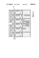
- FIG. 2 comprises a front view of a radio control console
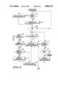
- FIG. 3 comprises a flow chart depicting operation of the invention.
- CAD computer aided dispatch
- This system includes generally an appropriate CAD host computer (101), a radio control console (102), and a central electronics bank (CEB)(103) that links the CAD host computer (101)to the console (102).
- CEB central electronics bank
- the CEB (103) includes a CAD interface to MUX interface (CIMI)(104) that receives and sends data to and from the CAD host computer (101) and a TDM bus (105).
- the console (102) interfaces with the TDM bus (105) (and through it to the other components) through an operator MUX interface (OMI)(106).
- OMI operator MUX interface
- BIM base interface modules
- each BIM (107) controls a separate communication path, such as a channel pair.
- Control information from the CAD host computer (101), and radio control channel instructions and other acknowledgment signals from the console (102), are passed between each other and to other components within the CEB (103) through the appropriate CIMI (104) and OMI (106) via the TDM bus (105).
- CIMI CIMI
- OMI OMI
- the console includes a plurality of channel control modules (CCM) (201).
- CCMs (201) comprises an assignable CCM and includes an alphanumeric display (202) to provide an appropriate indication of the current channel assignment for that particular CCM (201).
- the first CCM (203) has been assigned to the POLICE 1 group
- the second CCM (204) has been assigned to the FIRE 1 group.
- an appropriate software routine can be locatedin the OMI (106) described earlier with respect to FIG. 1.
- the OMI (106) Upon detecting afailure to receive appropriate control signals from the CAD host computer (101), either due to a failure of the CAD host computer (101) itself or the link connecting the CAD host computer (101) to the console (102), or upon detecting receipt of an appropriate data packet from the CAD host computer (101) so instructing the OMI (106), the OMI (106) will initiate afailure mode of operation. Referring to FIG. 3, the general operation of this failure mode will be described.
- the routine Upon initiating the failure mode, the routine will determine, in seriatim fashion, whether any CCMs (201) support an emergency communication (301), and if not, deassign those CCMs (304). (Depending upon the type of communications network supported by the console (102), the emergency communications can be identified in a variety of ways. Typically, emergency calls represent those communications that are initiated in a particular way by a communicating unit, which includes an appropriate callinitiation or call maintenance signal that identifies the communication as being of a high priority nature such as an emergency call.) When the routine determines that a particular CCM (201) does support an emergency call, the routine places an identification of that CCM (201) in an appropriate queue (302) to record that the CCM has not completed its failure processing.
- the failure mode routine causes the control console (102) to deassign the CCM (304). For example, with reference to FIG. 2, if the first CCM (203) had originally been assigned to the POLICE 1 group, and was not, at the time of entering the failure mode, supporting an emergency call, the first CCM (203) would not have been placed in the queue, and would be deassigned from the POLICE 1 group. Conversely, if the second CCM (204) were, at the time of entering the failure mode, supporting an emergency call, it would have been listed in the queue and would not have been reassigned by the routine at the point indicated.
- the routine determines whether that CCM (201) has been earlier deassigned by the routine (306). If the CCM in question has not been deassigned, the deassignment has not occurred because the CCM was servicing an emergency call. Therefore, the CCM (201) will not be reassigned and the routine will continue. The routine then determines whether each CCM (201) has a previously established default assignment (305). Each assignable CCM (201) can have associated with it atleast one default assignment for use during a failure mode. When a CCM (201) having such a default assignment has been located the routine determines whether a duplicate assignment exists (307).
- a duplicate assignment can exist when a default assignment for a first CCM (201) matches the current, and not yet deassigned, assignment for another CCM. If no such default assignment exists, the routine assigns the CCM itsappropriate default assignment (308). Otherwise, if a duplicate assignment does exist, the routine determines whether the duplicate CCM has emergencyactivity (309). If the duplicate does have an active emergency, it will notbe deassigned and hence the first CCM will not be assigned to its default assignment. The first CCM will be saved in the queue (313) so that it can be processed later. Otherwise, if the duplicate does not have an active emergency, the duplicate CCM will be deassigned and the original CCM will be assigned to its appropriate default assignment (310).
- the routine determines whether the queue has emptied. If it has not, the process can be repeated (314) for individual queue listed CCMs. When repeating the process for these queue identified CCMs, the steps described above relating to "Last CCM” (303), "Last CCM Default Assignment” (311), and “Queue Empty” (312) can be deleted, as indicated bythe phantom lines that depict those steps. To the extent the emergency calls have terminated in ordinary course, the CCMs can be removed from thequeue and deassigned for appropriate reassignment to a default assignment or for quiescent deassigned operation.
- an appropriate acknowledgment can be transmitted to the host computer (101) to indicate completion of the deassigning and reassignment tasks. Also, if desired, periodic updates could be sent to the CAD host computer (101) to keep the host apprised of the deassignment and reassignment process as it occurs.
Abstract
Description
Claims (12)
Priority Applications (1)
| Application Number | Priority Date | Filing Date | Title |
|---|---|---|---|
| US07/213,408 US4901314A (en) | 1988-06-30 | 1988-06-30 | Failsoft radio control console |
Applications Claiming Priority (1)
| Application Number | Priority Date | Filing Date | Title |
|---|---|---|---|
| US07/213,408 US4901314A (en) | 1988-06-30 | 1988-06-30 | Failsoft radio control console |
Publications (1)
| Publication Number | Publication Date |
|---|---|
| US4901314A true US4901314A (en) | 1990-02-13 |
Family
ID=22795008
Family Applications (1)
| Application Number | Title | Priority Date | Filing Date |
|---|---|---|---|
| US07/213,408 Expired - Lifetime US4901314A (en) | 1988-06-30 | 1988-06-30 | Failsoft radio control console |
Country Status (1)
| Country | Link |
|---|---|
| US (1) | US4901314A (en) |
Cited By (13)
| Publication number | Priority date | Publication date | Assignee | Title |
|---|---|---|---|---|
| US4995095A (en) * | 1990-03-05 | 1991-02-19 | Motorola, Inc. | Method and apparatus for utilizing unpresented communication groups |
| WO1991014278A1 (en) * | 1990-03-05 | 1991-09-19 | Motorola, Inc. | A method and apparatus for automatically executing system reconfigurations |
| US5371492A (en) * | 1989-12-29 | 1994-12-06 | Motorola, Inc. | Method and apparatus for automatically executing system reconfigurations |
| US5479477A (en) * | 1994-03-03 | 1995-12-26 | Motorola, Inc. | Method and apparatus for assigning a control module to a communication resource in a dispatch radio communication system |
| US5699353A (en) * | 1993-11-24 | 1997-12-16 | Ericsson Ge Mobile Communications, Inc. | Extended trunked RF communications systems networking |
| US5754960A (en) * | 1991-02-22 | 1998-05-19 | Ericsson Inc. | Display console and user interface for multisite RF trunked system |
| EP0912016A2 (en) * | 1997-10-14 | 1999-04-28 | Lucent Technologies Inc. | Method for access control in a multiple access system for communications networks |
| US5999820A (en) * | 1997-04-30 | 1999-12-07 | Ericsson Inc. | Dispatch console having communication modules with caller tracking feature |
| US6173168B1 (en) * | 1998-04-22 | 2001-01-09 | Telefonaktiebolaget Lm Ericsson | Optimized cell recovery in a mobile radio communications network |
| US20030013477A1 (en) * | 2001-07-12 | 2003-01-16 | Mcalinden Paul | Controlling dual processors in cellular telephones |
| US20030055934A1 (en) * | 2001-09-20 | 2003-03-20 | Shane Lincke | Computer aided dispatch system and method for automatically distributing current status information to mobile units |
| US7200110B1 (en) * | 1999-03-24 | 2007-04-03 | Alcatel Canada Inc. | Method and apparatus for prioritized release of connections in a communications network |
| US20080279596A1 (en) * | 2007-05-09 | 2008-11-13 | Xerox Corporation | Low graininess printing and micr printing with scmb and ea-scmb systems |
Citations (2)
| Publication number | Priority date | Publication date | Assignee | Title |
|---|---|---|---|---|
| US4709365A (en) * | 1983-10-31 | 1987-11-24 | Beale International Technology Limited | Data transmission system and method |
| US4803681A (en) * | 1986-07-08 | 1989-02-07 | Nec Corporation | Data transmission control system |
-
1988
- 1988-06-30 US US07/213,408 patent/US4901314A/en not_active Expired - Lifetime
Patent Citations (2)
| Publication number | Priority date | Publication date | Assignee | Title |
|---|---|---|---|---|
| US4709365A (en) * | 1983-10-31 | 1987-11-24 | Beale International Technology Limited | Data transmission system and method |
| US4803681A (en) * | 1986-07-08 | 1989-02-07 | Nec Corporation | Data transmission control system |
Cited By (15)
| Publication number | Priority date | Publication date | Assignee | Title |
|---|---|---|---|---|
| US5371492A (en) * | 1989-12-29 | 1994-12-06 | Motorola, Inc. | Method and apparatus for automatically executing system reconfigurations |
| WO1991014278A1 (en) * | 1990-03-05 | 1991-09-19 | Motorola, Inc. | A method and apparatus for automatically executing system reconfigurations |
| US4995095A (en) * | 1990-03-05 | 1991-02-19 | Motorola, Inc. | Method and apparatus for utilizing unpresented communication groups |
| US5754960A (en) * | 1991-02-22 | 1998-05-19 | Ericsson Inc. | Display console and user interface for multisite RF trunked system |
| US5699353A (en) * | 1993-11-24 | 1997-12-16 | Ericsson Ge Mobile Communications, Inc. | Extended trunked RF communications systems networking |
| US5479477A (en) * | 1994-03-03 | 1995-12-26 | Motorola, Inc. | Method and apparatus for assigning a control module to a communication resource in a dispatch radio communication system |
| US5999820A (en) * | 1997-04-30 | 1999-12-07 | Ericsson Inc. | Dispatch console having communication modules with caller tracking feature |
| EP0912016A2 (en) * | 1997-10-14 | 1999-04-28 | Lucent Technologies Inc. | Method for access control in a multiple access system for communications networks |
| EP0912016A3 (en) * | 1997-10-14 | 2000-01-05 | Lucent Technologies Inc. | Method for access control in a multiple access system for communications networks |
| US6567416B1 (en) | 1997-10-14 | 2003-05-20 | Lucent Technologies Inc. | Method for access control in a multiple access system for communications networks |
| US6173168B1 (en) * | 1998-04-22 | 2001-01-09 | Telefonaktiebolaget Lm Ericsson | Optimized cell recovery in a mobile radio communications network |
| US7200110B1 (en) * | 1999-03-24 | 2007-04-03 | Alcatel Canada Inc. | Method and apparatus for prioritized release of connections in a communications network |
| US20030013477A1 (en) * | 2001-07-12 | 2003-01-16 | Mcalinden Paul | Controlling dual processors in cellular telephones |
| US20030055934A1 (en) * | 2001-09-20 | 2003-03-20 | Shane Lincke | Computer aided dispatch system and method for automatically distributing current status information to mobile units |
| US20080279596A1 (en) * | 2007-05-09 | 2008-11-13 | Xerox Corporation | Low graininess printing and micr printing with scmb and ea-scmb systems |
Similar Documents
| Publication | Publication Date | Title |
|---|---|---|
| US4901314A (en) | Failsoft radio control console | |
| US4945355A (en) | System for cooperatively reassigning duties in a multiple controller environment | |
| US5371492A (en) | Method and apparatus for automatically executing system reconfigurations | |
| EP0530199B1 (en) | A method for automatically executing system reconfigurations | |
| CA1304132C (en) | Fail-soft architecture for public trunking system | |
| JP2000115828A (en) | Radio base station device, and control channel assigning method therefor | |
| JP2000059519A (en) | Information collection system using portable mobile communication system | |
| JPS6368345A (en) | Controller for factory automation | |
| US5764986A (en) | Method for loading secondary stations with a structure representing initial program load information to be sent in a computer communication system | |
| CA2062918A1 (en) | Method for operating a networked computer system to minimize data conversion overhead | |
| JP2529995B2 (en) | Failure handling method for multi-drop line | |
| JP3012400B2 (en) | Startup inspection method for wireless data transmission equipment | |
| JPS6058741A (en) | Method for transmitting supervising instruction in remote supervisory and controlling equipment | |
| JPH0537531A (en) | Master station backup system | |
| KR100224321B1 (en) | Apparatus and control method for connection between earth station system and network management system | |
| JPH03136528A (en) | Order system for emergency order device | |
| JPH01243738A (en) | Private branch radio station equipment | |
| JP2746201B2 (en) | Bus connection control method and device | |
| JPH045301B2 (en) | ||
| JPH07212875A (en) | Remote supervisory device | |
| JPS5970054A (en) | Controlling device of transmission | |
| JP3116476B2 (en) | Redundant switching method | |
| JP2002010327A (en) | Supervisory control apparatus for radio system | |
| JPH04144339A (en) | Selection system for host computer and pad | |
| JPH06100261A (en) | Test device for elevator |
Legal Events
| Date | Code | Title | Description |
|---|---|---|---|
| AS | Assignment |
Owner name: MOTOROLA, INC., SCHAUMBURG, ILLINOIS, A CORP. OF D Free format text: ASSIGNMENT OF ASSIGNORS INTEREST.;ASSIGNOR:LOHRBACH, JEFFREY G.;REEL/FRAME:004902/0768 Effective date: 19880627 Owner name: MOTOROLA, INC., A CORP. OF DE., ILLINOIS Free format text: ASSIGNMENT OF ASSIGNORS INTEREST;ASSIGNOR:LOHRBACH, JEFFREY G.;REEL/FRAME:004902/0768 Effective date: 19880627 |
|
| STCF | Information on status: patent grant |
Free format text: PATENTED CASE |
|
| FEPP | Fee payment procedure |
Free format text: PAYOR NUMBER ASSIGNED (ORIGINAL EVENT CODE: ASPN); ENTITY STATUS OF PATENT OWNER: LARGE ENTITY |
|
| FPAY | Fee payment |
Year of fee payment: 4 |
|
| FPAY | Fee payment |
Year of fee payment: 8 |
|
| FPAY | Fee payment |
Year of fee payment: 12 |