This application is a continuation of application Ser. No. 109,450, filed on Oct. 19, 1987, now abandoned.
FIELD OF THE INVENTION
The present invention relates in general to satellite communication systems and is particularly directed to a mechanism for correcting for the frequency offset through a satellite communication channel imparted by the (drift-susceptible) translation reference oscillator in the satellite.
BACKGROUND OF THE INVENTION
The successful operation of satellite communication networks, such as time division multiple access (TDMA) systems, depends upon the ability of the receiver equipment at the respective sites to be accurately tuned to the incoming signal from another site. Because a TDMA system employs burst communications it is not possible to use a conventional automatic frequency adjustment mechanism which relies upon the presence of a continuous carrier. Consequently it has been a common (and extremely costly) practice to provide each site with a high precision oscillator which monitors an effectively perfectly stable pilot frequency transmitted from a master site and determines the offset through the satellite.
One proposal to eliminate the need for a precision oscillator at each site and thereby reduce the expense of the equipment at the remote sites is described in the Luginbuhl et al, U.S. Pat. No. 4,509,200, entitled `Satellite Telecommunication System`. Pursuant to the patented scheme a high precision pilot tone oscillator is installed at a central site, the only apparent purpose of which is to measure frequency offset (drift) through the satellite. By monitoring the pilot tone over a loop back to itself the master site is able to measure the offset through the satellite, which must be corrected. The measured error is then transmitted as an information signal for use at the remote site. The remote site must strip off the data and then use the data to properly tune itself (not having the benefit of a precision local oscillator). This presupposes that the remote site is properly tuned to begin with, something that the coarse oscillator used by the remote site cannot guarantee. Consequently, the procedure is questionable, at best.
SUMMARY OF THE INVENTION
In accordance with the present invention, rather than make an error (frequency translation) measurement and then transmit that error as an information signal, as in the above-referenced questionable patented scheme, the measured frequency offset through the satellite is used to premodify signals transmitted from the master site to a remote site such that there is an effective complementary frequency translation on the uplink. As a result, the pre-offset signals conveyed through the satellite and received by a remote site will have been translated back to their correct frequency and can be readily demodulated by the remote site.
More specifically, in a time division multiple access satellite communications system having a master site and one or more remote sites, frequency offset through the translation oscillator in the satellite is corrected by looping a reference channel at the master site using a high precision reference oscillator. Any frequency offset subjected by a pilot tone transmitted over the reference channel is used to fine tune the master site down-converter and to remove the offset and precorrect an up-converter that operates off the precision oscillator and through which information signals to be transmitted to a remote site are transmitted. Because of this precorrection, the signals received by the remote site are at the correct frequency, so that the precision reference oscillator frequency component of the received signal can be used to adjust the frequency of signals transmitted from the remote site back to the master site.
BRIEF DESCRIPTION OF THE DRAWINGS
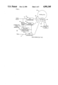
FIG. 1 is a diagrammatic illustration of a satellite communications system employing a frequency offset (translation) correction scheme in accordance with a first embodiment of the invention;
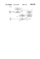
FIG. 2 is a diagrammatic illustration of the configuration of a remote site in the system of FIG. 1;
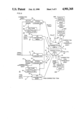
FIG. 3 is a diagrammatic illustration of a satellite communications system employing a frequency offset correction scheme in accordance with a second embodiment of the invention;
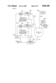
FIG. 4 is a diagrammatic illustration of the configuration of a signal fade prevention scheme for use with the system of FIG. 3; and
FIG. 5 is a diagrammatic illustration of a satellite communications system employing a frequency offset correction scheme in accordance with a third embodiment of the invention.
DETAILED DESCRIPTION
Before describing in detail the particular improved frequency translation correction scheme in accordance with the present invention, it should be observed that the present invention resides primarily in a novel structural combination of conventional communication circuits and components and not in the particular detailed configurations thereof. Accordingly, the structure, control and arrangement of these conventional circuits and components have been illustrated in the drawings by readily understandable block diagrams which show only those specific details that are pertinent to the present invention, so as not to obscure the disclosure with structural details which will be readily apparent to thoseskilled in the art having the benefit of the description herein. Thus, the block diagram illustrations of the Figures do not necessarily represent the mechanical structural arrangement of the exemplary system, but are primarily intended to illustrate the major structural components of the system in a convenient functional grouping, whereby the present invention may be more readily understood.
Referring now to FIG. 1, a satellite communications system is shown diagrammatically as comprising a central or master site 10, a satellite 20and a remote site 30. It is to be understood that remote site 30 may comprise one or more geographically separated sites, each of which is uniquely identified by a prescribed time slot during which communications from the remote site to the master site over a time division multiple access (TDMA) link are effected.
As described above, only the master site contains a precision oscillator through which communications between the master and remote sites are controlled. Regardless of the precision and of the equipment at the mastersite, however, there is a frequency offset through the satellite 20 (encompassing retransmission frequency and drift frequency) which must be taken into account to assure proper reception for both directions of transmission. This correction is accomplished at the master site by transmitting a reference or pilot tone (e.g. intermediate frequency (IF)) over link 11 to an up-converter 12 which utilizes a precision reference oscillator (e.g. 10 MHz). Up-converter 12 outputs a pilot tone FP over a master site-satellite-master site loop 40, so that at the master site the received signal contains the pilot tone Fp plus the frequency offset ΔF imparted by the satellite 20. This received signal is coupled to a down-converter 13. The output of down-converter 13 is coupled to a pilot receiver 14, which also is coupled to receive the pilot or reference tone supplied over link 11. The output of pilot receiver 14 is a voltage representative of the frequency offset imparted by satellite 20 (including any drift) and is used to drive a voltage controlled oscillator 15, the output of which is representative of the offset and is used to adjust the operation of down-converter 13. As a consequence, the output of down-converter 13 will be at the correct frequency (for example the original pilot tone supplied over link 11).
In accordance with the present invention, the output of voltage controlled oscillator 15 is also coupled to a further up converter 16 to which data channel 17 is coupled. Data channel 17 contains time division multiplex signals intended for transmission to the remote site 30 via the satellite 20. Using the frequency offset provided by voltage controlled oscillator 15, up-converter 16 introduces a precorrection frequency offset that effectively counters the frequency shift imparted by the satellite 20. As a result, the time division multiplex signals that are transmitted over a data channel 50 from the master site 10 through the satellite 20 to the remote site 30 and received at the remote site 30 have the accuracy of the(10 MHz) precision reference oscillator employed at the master site.
At the remote site, diagrammatically illustrated in FIG. 2, the incoming TDM frequency supplied to a down-converter 31 which is driven by a coarse local oscillator 32. The output of down-converter 31 is coupled to a frequency counter 33 which produces an output indicative of the actual down-converted frequency (e.g. 10.702 MHz). The output of frequency counter 33 is preferably a digitized code which is coupled to a remote site control processor 34. Processor 34 compares the actual frequency datasupplied by frequency counter 33 with a nominal value to which the local (coarse) oscillator has been preset. Assuming, for purposes of illustration, that the local oscillator has been preset at 10.700 MHz, (a frequency value preprogrammed into processor 34) then an error of 2 KHz will be produced. Processor 34 contains a communications control program through which the operation of a remote site transmit frequency synthesizer 35 is controlled. The control program computes a precorrected transmission frequency based upon the error (e.g the 2 KHz error) and computes a correction transmission frequency due to the error in the localoscillator 32. As a result, the output frequency produced by synthesizer 35is precorrected to take into account the error in the local oscillator 32. The output of synthesizer 35 is coupled to an up-converter 37 to which data to be transmitted from the remote site 30 to the master site 10 is supplied over link 36. The output of up-converter 37 is transmitted over an up-link communication channel 60 from remote site 30 through satellite 20 to master site 10. This remote site-to-master site communication channel 60 undergoes the frequency offset imparted by satellite 20 in the same manner that the pilot frequency, described above, is impacted over loop 40. With down-converter 13 receiving the remote site-to-master site TDMA channel, the incoming data will be corrected in the same manner that the original pilot frequency was corrected, so that the output of down-converter 13 will be at the correct frequency of interest.
In the system described above, the communications equipment aboard the satellite 20 employs a single translation oscillator which, together with the drift through the link, imparts the frequency offset which is precorrected pursuant to the present invention. In some communication satellites, however, more than one translation oscillator is employed, particularly where remote stations are geographically disbursed over a wide continental area, such as a north American continent east/west network. In such geographically disbursed networks, the satellite links may be prededicated such that all up-links in the eastern half of a geographical area may employ one dedicated oscillator within the satellite, while all up links on the western half of the area may employ another dedicated translation oscillator, the frequency of which is different from that of the one oscillator. When the master site cannot seeboth the east and west downlinks, the correction scheme becomes more difficult.
FIG. 3 diagrammatically illustrates an embodiment of a satellite communications network incorporating equipment described above with reference to FIG. 1, but modified to take into account the use of separatetranslation oscillators in the satellite for such a geographically disbursed system. In the embodiment shown in FIG. 3, master site 10 is configured identically to that of the master site 10 of the network shown in FIG. 1. Similarly, an east remote site 30E corresponds to the remote site 30 of the network shown in FIG. 1, with satellite 20 containing a dedicated translation oscillator specifically assigned for communications originating from the eastern portion of the network.
Also shown in FIG. 3 is a geographically separated western site 19 which communicates over a east master-to-west channel 70 through the same translation oscillator that carries channel 50 for east-to-east transmissions. Consequently, a west up-converter 26 which receives incoming TDM signals to be transmitted over channel 70 to a remote west site 30W is precorrected by the same frequency offset produced by voltage controlled oscillator 15 which drives up-converter 16 for the eastern portion of the system.
For remote west-master site transmissions, however, satellite 20 employs a separate translation oscillator for effecting communications between the remote site 30W and the master site 10. Consequently, the correction frequency offset imparted for the eastern portion of the link cannot be used for the return from the west remote site. Instead, compensation is provided by the use of an additional high accuracy reference frequency generated at a special remote site 30S and looped through the second translation oscillator in the satellite 20, via communication path 80, to a separate pilot receiver 21 in the master site. The special remote terminal 30S generates a continuous unmodulated pilot which is applied to a frequency lock loop dedicated for the purpose employing down-converter 22, pilot receiver 21 and voltage control oscillator 25, connected in a feedback loop corresponding to the correction loop of down-converter 13, pilot receiver 14 and voltage controlled oscillator 15 for the first translation oscillator employed in the satellite. TDM signals which are transmitted from the remote west site 30W over link 90 through the second translation oscillator within the satellite 20 are corrected through the feedback loop which monitors the pilot tone from the special remote terminal 30S, so that the output of down-converter 22 restores the original signals transmitted from site 30W to their correct frequency.
To guard against the possibility of a rain fade from disrupting the pilot transmission from remote site 30S, the use of a second special pilot tone (such as an 11 MHz tone) may be transmitted from another special remote site geographically separated from remote site 30S. A scheme for providingsuch a rain fade prevention scheme is diagrammatically illustrated in FIG. 4. As shown therein, rather than use a single special remote site 30S, a pair of special pilot generating sites 30S-1 and 30S-2, geographically displaced from one another and remote with respect to the remote west site30W of FIG. 3, are employed. Each of sites 30S-1 and 30S-2 generates a pilot that is offset in frequency from the pilot tone generated by the other site. Each pilot is transmitted through the second translation oscillator within the satellite 20 over respective loop 80-1 and 80-2 to the master site 10. At the master site, in place of a single frequency lock loop for the special pilot tone, as described above with reference toFIG. 3, a pair of pilot receivers 34-1, 34-2 are employed. For the first special pilot tone from site 30S-1, master site 10 employs a down converter 32-1, a pilot receiver 34-1 and a feedback voltage controlled oscillator 35-1. For the second special pilot tone, respective down converter 32-2, pilot tone receiver 34-2 and voltage controlled oscillator35-2 are used.
The status output of each respective pilot receiver 34-1 and 34-2 is coupled to a decision logic circuit 41. Logic circuit 41 monitors the lockstatus of each pilot receiver 34-1 and 34-2 and controls a switch 42 which is coupled to the output of each of voltage controlled oscillators 35-1 and 35-2 to a further down converter 32-3 so as to drive down converter 32-3 with the locked pilot receiver and enable recovery of the TDMA signals from the remote site 30W over transmission channel 90.
FIG. 5 diagrammatically illustrates a further embodiment of a satellite communications network, incorporating equipment described above with reference to FIG. 1, that has been modified to take into account the use of separate translation oscillators in the satellite for a geographically disbursed system. Like the embodiment shown in FIG. 3, described above, the system shown in FIG. 5 employs a master site (east master site 110), and a special (west) remote site 130S, each of which contains a respectiveprecision oscillator to enable accurate measurement of and compensation forfrequency translations through respective translators 220 and 210 for east bound and west bound transmissions, respectively, of a satellite 200 whichdiffers from satellite 20 in the way the translation oscillators are dedicated. Also shown in FIG. 5 are respective east and west remote sites 130E and 130W, respectively.
The master or hub site 110 contains a first, highly stable reference oscillator 111, the output of which is coupled over link 112 to a pilot tone generator 113, to a pilot up-converter 115 and to a synthesized pilotreceiver 141. Pilot generator 113 couples a fixed pilot tone A over link 114 to pilot up-converter 115 and to an east pilot receiver 142. The output of pilot up-converter 115 is coupled to a signal splitter 122 and coupled therefrom to first inputs of respective west and east summing circuits 124 and 131. East summing circuit 131 has a second input coupled over link 151 to the output of an east up-converter 145 which receives a master-to-east remote data signal B over link 152. The local oscillator input for east up-converter 145 is supplied over link 144 from the output of a voltage controlled oscillator within a down-converter 134, that is driven by east pilot receiver 142. Similarly, west summing circuit 124 hasa second input coupled over link 156 to the output of a west up-converter 154, which receives a master-to west remote data signal C over link 155. The local oscillator input for west up-converter 154 is supplied over link153 from the output of a voltage controlled oscillator within synthesized pilot receiver 141.
The outputs of summing circuits 124 and 131 are coupled to respective vertical and horizontal polarization inputs to a transmit/receive antenna unit 125. Unit 125 also includes a horizontally polarized output coupled over link 133 to down-converter 134. As shown in FIG. 5, horizontally polarized signals are employed for west transmissions, while vertically polarized signals are used for east transmissions.
East remote site 130E contains a transmit/receive antenna unit 161 coupled to an associated up-converter 162 and down-converter 163 for coupling datasignals with respect to a local east interface link. Similarly, west remotesite 130W contains a transmit/receive antenna unit 171 coupled to an associated up-converter 172 and a down-converter 173 for coupling data signals with respect to a local west interface link.
Special remote (west) site 130S contains a transmit/receive antenna 181 coupled to an associated up-converter 182 and a down-converter 183, each of which is driven by a high precision, stabilized local oscillator 190. The output of down-converter 183 is looped through filter amplifier 184 tothe input of up-converter 182 which has been offset in frequency by P (e.g.9 MHz).
OPERATION
As pointed out above, in accordance with the embodiment of the invention illustrated in FIG. 5, satellite 200 contains a dedicated frequency translator 210 through which master site 110 carries out communications with west remote site 130W, and a dedicated frequency translator 220 through which master site 110 carries out communications with east remote site 130E. For measuring the frequency offset that takes place during eastcommunications master site 110 employs precision oscillator 111. To obtain a measurement of the frequency offset that takes place during west communications, master site 110 makes use of the precision oscillator 190 at special remote site 130S.
More particularly, considering the measurement of the offset over the east link, a high precision pilot tone (e.g. 10 MHz), referenced to high precision oscillator 110 and shown diagrammatically in FIG. 5 as signal A is transmitted from master site 110 over east uplink 231 to satellite 200.Via east transceiver 220, satellite 200 returns the pilot signal A over east downlink 232 to the master site as a signal A+ΔE, where ΔE is the offset through east transceiver unit 220 of satellite 200.The received signal is coupled over link 133 to down-converter 134, which is tuned by pilot receiver 142 to remove the frequency shift caused by theerror (-ΔE) in the east translation oscillator in the satellite. The frequency shift itself (-ΔE) is derived from the voltage controlled oscillator, to which down-converter 134 is referenced, in accordance with the output of east pilot receiver 142 on link 143, and is supplied over link 144 to east up-converter 145 for premodifying TDM communications to an east remote site, identified as signal B on input link 152, prior to transmission. Consequently, outgoing eastbound data signals are transmitted at a complementary frequency B-ΔE over uplink 231. When relayed from the satellite over downlink 261, the offset through the satellite restores the data signals to their original frequency B.
Communications (DE) from east remote site 130E are transmitted over uplink 262 and subjected to the offset ΔE through the satellite, so as to be relayed over downlink 232 as DE +ΔE to the master site. As pointed out above, since down-converter 134 is referenced to the output of east pilot receiver 142, the offset (ΔE) is removed, so that the original frequency DE transmitted by east remote site 130E is output over link 135.
Precision pilot signal A is also used in conjunction with a second precision signal P to measure the offset through the west transceiver 210 within satellite 200. For this purpose the pilot signal A is transmitted over west uplink 241 and downlink 242 to special remote site 130S. The effect of the offset ΔW through the satellite is shown in FIG. 5 as a signal A+ΔW. At remote site 130S, the received signal is offset bya prescribed precision reference P (e.g. from one to nine MHz.) as established by high stability oscillator 190 and retransmitted over uplink251 at a frequency A+ΔW+P to the master site. Since this retransmitted signal is passed through the east translator it emerges on downlink 232 at a frequency A+ΔW+P+ΔE. At the master site, theoutput of down-converter 134, in which the east offset (ΔE) is removed, is coupled to synthesized pilot receiver 141 which is referenced to oscillator 111, so that the west offset -ΔW is extracted over link 153. The west frequency shift itself (-ΔW) as derived from the voltage controlled oscillator, to which synthesized pilot receiver 141 is referenced, is supplied over link 153 to west up-converter 154 for premodifying TDM communications to west remote site 130W, identified as signal C on input link 155, prior to transmission. Consequently, outgoing westbound data signals are transmitted at a complementary frequency C-ΔW over uplink 241. When relayed from the satellite over downlink 271, the offset through the satellite restores the data signals to their original frequency C.
Communications (DW) from west remote site 130W are transmitted over uplink 272 and subjected to the offset ΔE through the satellite, so as to be relayed over downlink 232 as DW +ΔE to the master site. As pointed out above, since down-converter 134 is referenced to the output of east pilot receiver 142, the offset (ΔE) is removed so that the original frequency DW transmitted by west remote site 130W is output over link 135.
As will be appreciated from the foregoing description of the present invention, in a time division multiple access satellite communications system having a master site and one or more remote sites, frequency offsetthrough one or more translation oscillators in the satellite is corrected by looping a reference pilot at the master site using a high precision reference oscillator. Any frequency offset to which the pilot is subjectedis used to fine tune the master site down converter, so as to remove the offset and precorrect an up-converter that operates off the precision oscillator and through which information signals to be conveyed to a remote site are transmitted. Because of this precorrection, the signals received by the remote site are at the correct frequency, so that it is unnecessary to install a precision reference oscillator at each remote site. The highly precise received signal can now be used as a reference tocontrol the frequency of signals transmitted from the remote site back to the master site.
While we have shown and described several embodiments in accordance with the present invention, it is to be understood that the same is not limitedthereto but is susceptible to numerous changes and modifications as known to a person skilled in the art, and we therefore do not wish to be limitedto the details shown and described herein but intend to cover all such changes and modifications as are obvious to one of ordinary skill in the art.