US4901383A - Modular frame for a water bed - Google Patents
Modular frame for a water bed Download PDFInfo
- Publication number
- US4901383A US4901383A US07/322,202 US32220289A US4901383A US 4901383 A US4901383 A US 4901383A US 32220289 A US32220289 A US 32220289A US 4901383 A US4901383 A US 4901383A
- Authority
- US
- United States
- Prior art keywords
- frame
- rails
- coupler
- couplers
- side plates
- Prior art date
- Legal status (The legal status is an assumption and is not a legal conclusion. Google has not performed a legal analysis and makes no representation as to the accuracy of the status listed.)
- Expired - Fee Related
Links
- XLYOFNOQVPJJNP-UHFFFAOYSA-N water Substances O XLYOFNOQVPJJNP-UHFFFAOYSA-N 0.000 title claims abstract description 10
- 230000008878 coupling Effects 0.000 claims abstract description 14
- 238000010168 coupling process Methods 0.000 claims abstract description 14
- 238000005859 coupling reaction Methods 0.000 claims abstract description 14
- BFMKFCLXZSUVPI-UHFFFAOYSA-N ethyl but-3-enoate Chemical compound CCOC(=O)CC=C BFMKFCLXZSUVPI-UHFFFAOYSA-N 0.000 claims abstract description 6
- 239000006260 foam Substances 0.000 claims abstract description 6
- 239000007788 liquid Substances 0.000 claims description 8
- 235000014676 Phragmites communis Nutrition 0.000 claims description 6
- 229910052751 metal Inorganic materials 0.000 claims description 4
- 239000002184 metal Substances 0.000 claims description 3
- 239000004677 Nylon Substances 0.000 claims description 2
- 229920001778 nylon Polymers 0.000 claims description 2
- 239000006261 foam material Substances 0.000 description 3
- 230000004048 modification Effects 0.000 description 1
- 238000012986 modification Methods 0.000 description 1
- 230000000717 retained effect Effects 0.000 description 1
Images


Classifications
-
- A—HUMAN NECESSITIES
- A47—FURNITURE; DOMESTIC ARTICLES OR APPLIANCES; COFFEE MILLS; SPICE MILLS; SUCTION CLEANERS IN GENERAL
- A47C—CHAIRS; SOFAS; BEDS
- A47C27/00—Spring, stuffed or fluid mattresses or cushions specially adapted for chairs, beds or sofas
- A47C27/08—Fluid mattresses or cushions
- A47C27/085—Fluid mattresses or cushions of liquid type, e.g. filled with water or gel
-
- F—MECHANICAL ENGINEERING; LIGHTING; HEATING; WEAPONS; BLASTING
- F16—ENGINEERING ELEMENTS AND UNITS; GENERAL MEASURES FOR PRODUCING AND MAINTAINING EFFECTIVE FUNCTIONING OF MACHINES OR INSTALLATIONS; THERMAL INSULATION IN GENERAL
- F16B—DEVICES FOR FASTENING OR SECURING CONSTRUCTIONAL ELEMENTS OR MACHINE PARTS TOGETHER, e.g. NAILS, BOLTS, CIRCLIPS, CLAMPS, CLIPS OR WEDGES; JOINTS OR JOINTING
- F16B2200/00—Constructional details of connections not covered for in other groups of this subclass
- F16B2200/65—Miter joints
-
- F—MECHANICAL ENGINEERING; LIGHTING; HEATING; WEAPONS; BLASTING
- F16—ENGINEERING ELEMENTS AND UNITS; GENERAL MEASURES FOR PRODUCING AND MAINTAINING EFFECTIVE FUNCTIONING OF MACHINES OR INSTALLATIONS; THERMAL INSULATION IN GENERAL
- F16B—DEVICES FOR FASTENING OR SECURING CONSTRUCTIONAL ELEMENTS OR MACHINE PARTS TOGETHER, e.g. NAILS, BOLTS, CIRCLIPS, CLAMPS, CLIPS OR WEDGES; JOINTS OR JOINTING
- F16B2200/00—Constructional details of connections not covered for in other groups of this subclass
- F16B2200/67—Rigid angle couplings
-
- Y—GENERAL TAGGING OF NEW TECHNOLOGICAL DEVELOPMENTS; GENERAL TAGGING OF CROSS-SECTIONAL TECHNOLOGIES SPANNING OVER SEVERAL SECTIONS OF THE IPC; TECHNICAL SUBJECTS COVERED BY FORMER USPC CROSS-REFERENCE ART COLLECTIONS [XRACs] AND DIGESTS
- Y10—TECHNICAL SUBJECTS COVERED BY FORMER USPC
- Y10S—TECHNICAL SUBJECTS COVERED BY FORMER USPC CROSS-REFERENCE ART COLLECTIONS [XRACs] AND DIGESTS
- Y10S5/00—Beds
- Y10S5/915—Beds with vibrating means
Abstract
A frame is adapted to surround a liguid-filled sack and a rigid support. The sack is placed on the upper surface of the support so as to constitute the cushion-like upper portion of a water bed. The frame has four rails which are interconnected to form a rectangular shape. The frame includes at least two, preferably four, detachably interconnected sections. The rails may be made of ethyl vinyl acetate. Alternatively, each of the rails has a tubular foam body and a rigid central rod fitted within the tubular foam body. In one embodiment, the frame includes four rails, four corner elements and four coupling units interconnecting the rails and the corner elements.
Description
This invention relates to a frame for a water bed, more particularly to a modular frame for a water bed.
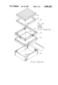
To increase the feeling of comfort derived from lying on a bed, a liquid-filled sack has been placed on a bedstead to serve as a cushion. Referring to FIG. 1, a conventional water bed of this type includes a frame 92 which keeps a sack 94 in place by surrounding the same. A rigid support 93 is also enclosed by the frame 92 below the sack 94. The combined assembly of the frame 92 and the support 93 is placed on a bedstead 91 in a casing 90. The frame 92 consists of two cross rails and two side rails and comprises a unitary piece which occupies a very large space. It is difficult to carry or transport the unitary frame 92 of the prior art. Referring to FIG. 2, because the frame 92 has an upper portion 95 formed of sponge and a lower portion 96 created from a rigid foam material, when the user of such a bed repeatedly and continually lies on the sack 94 for extended periods of time, he or she causes liquid in the sack 94 to push the frame 92 outward, thereby causing said frame 92 to deform or even break.
The main object of this invention is to provide a modular frame surrounding the liquid-filled sack of a water bed.
Another object of this invention is to provide a durable frame surrounding the liquid-filled sack of a water bed.
According to this invention, a frame is adapted to surround a liquid-filled sack and a rigid support. The sack is placed on the upper surface of the support so as to constitute the cushion-like upper portion of a water bed. The frame has four rails which are interconnected to form a rectangular shape. The frame includes at least two, preferably four, detachably interconnected sections. The rails may be made of ethyl vinyl acetate. Alternatively, each of the rails has a tubular foam body and a rigid central rod fitted within said tubular foam body.
Other features and advantages of this invention will become apparent in the following detailed description of the preferred embodiments of this invention, with reference to the accompanying drawings, in which:
FIG. 1 is an exploded view of a conventional water bed with a liquid-filled sack;
FIG. 2 is a sectional view taken along Line II--II of FIG. 1;
FIG. 3 is a perspective view of a frame according to a first embodiment of this invention;
FIG. 4 is an exploded view showing the rail of the frame according to the first embodiment of this invention;
FIG. 5 is a perspective view of a frame according to a second embodiment of this invention;
FIG. 6 is a perspective view showing the coupling unit of the frame according to the second embodiment of this invention;
FIG. 6A is a sectional view illustrating how to detachably interconnect the coupler and the connecting rod of the frame in accordance with the second embodiment of this invention;
FIG. 7 is a perspective view showing the corner element of the frame according to the second embodiment of this invention;
FIG. 8 is a schematic view illustrating how to fold the corner element of FIG. 7;
FIG. 9 is a perspective view showing the rail of the frame according to the second embodiment of this invention;
FIG. 10 is a cross-sectional view showing the rail of the frame according to the second embodiment of this invention;
FIG. 11 is a perspective view showing the coupling unit of a frame according to a third embodiment of this invention;
FIGS. 12 and 13 are schematic views illustrating the assembly of the rail and the coupling unit of a frame according to a fourth embodiment of this invention.
Referring to FIGS. 3 and 4, a frame of this invention includes four rails each of which has two end-to-end interconnected portions 97. As illustrated, each pair of adjacent rail 97 are interconnected securely at their adjacent ends. Two portions 97 of each rail have aligned cylindrical cavities C through which cylindrical rods 89 are passed. The portions 97 of the rails are made of ethyl vinyl acetate. Each portion 97 includes a fixed metal element 98 of an L-shaped cross-section. The metal elements 98 of each pair of aligned portions 97 of each pair of parallel rails are interconnected by two tensed nylon threads 99 so that each pair of adjacent portions 97 cannot separate from each other. When all the threads 99 are removed from the rails, each pair of adjacent portions 97 may be removed from each other. It can be appreciated that it is difficult to deform and break the frame due to the fact that the rails of the frame are made of ethyl vinyl acetate.
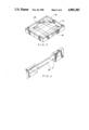
Referring to FIG. 5, another frame of this invention includes four rails 3, four generally L-shaped corner elements 2 and four coupling units 1 which interconnect the rails 3 and the corner elements 2. Each of the coupling units 1 includes two couplers 11 of a U-shaped cross-section and a connecting rod 12 interconnecting said couplers 11. Each of the couplers 11 includes two upright side plates and a bottom plate 112 interconnecting said side plates 111. The side plates 111 of each coupler 11 are perpendicular to the side plates 111 of the adjacent coupler 11. Each of the side plates 111 has a first vertical rib 113 projecting from the inner wall of the inner end portion thereof, and a second vertical rib 114 projecting from the inner wall of the outer end portion thereof.
The connecting rod 12 may be soldered to the bottom plates 112 of the couplers 11.
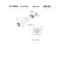
A preferred embodiment is shown in FIG. 6A which reduces the space occupied by the coupling units 1 when the frame is carried.
Referring to FIG. 6A, in each of the coupling units 1, each coupler 11 is connected detachably to a socket 120 which is secured to the end of the connecting rod 12. The socket 120 includes a cavity 121 formed in the end surface thereof, two wedged retaining projections 122 extending from the inner wall defining the cavity 121, and two holes 123 formed through the wall of the socket 120. A tongue unit 116 extends downward from the bottom plate 112 and has a middle strip M and two barb-like resilient jaws 117 each of which has a retaining groove 118 formed in the outer wall of the upper end portion thereof. As illustrated, when the tongue unit 116 is inserted into the cavity 121 of the socket 120, the retaining projections 122 engage with the retaining grooves 118 so that the tongue unit 116 is retained within the socket 120. A tool may be inserted through the holes 123 to push the jaws 117 inward so as to disengage the retaining projections 122 from the retaining grooves 118, after which the tongue unit 116 may be removed from the socket 120.
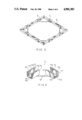
Referring to FIGS. 7 and 8, each of the corner elements 2 has two arms 20 which are connected to each other at the inner sides of their inner end surfaces 201 by a hinge 21. The arms 20 of each corner element 2 have aligned oblique inner end surfaces 201. As shown in FIG. 8, when the inner end surfaces 201 of the arms 20 overlap each other, the arms 20 are perpendicular to each other. Each of the arms 20 has two open-ended vertical slots 211 formed in two sides walls of the outer end portion thereof. The outer end of each arm 20 of corner element 2 is placed on the bottom plate 112 of one coupler 11 in such a manner that the slots 211 of said arm 20 engage with the first ribs 113 of said coupler 11.
Referring to FIG. 9, each of the rails 3 has two vertical slots 31 formed in two side walls of each end portion thereof. Each end portion of the rail 3 is placed on the bottom plate 112 of one coupler 11 in such a manner that the slots 31 of said rails engage with the second ribs 114 of said coupler 11. The rails 3 are preferably made of ethyl vinyl acetate. Alternatively, the rails 3 may be made of a foam material which is somewhat flexible. Because the foam material rail 3 is flexible and resilient, a reinforced metal or wooden rod 34, (see FIG. 10), may be provided through the rail 3.
Referring to FIG. 11, to prevent the side plates 111 from flexing relative to the bottom plate 112 when the user lies on the liquid-filled sack which is inside the frame, a rigid cross rod 115 may bridge the upper ends of the middle portions of the side plates 111 of one coupler 11.
Referring to FIG. 12, the manner in which the coupler interconnects the corner element and the rail may be changed. As illustrated, the coupler A includes an engagement hole 16 formed through one side plate of one end portion thereof, and a vertical rib 17 projecting from the inner walls of the side plates of the other end portion of said coupler A. The ribs 17 are connected to the adjacent arm of rail in the same manner as that of the embodiment of FIG. 5. The rail or arm B which is connected to the left end of the coupler A includes a groove 80 formed in the side wall of the right end portion thereof, and a spring reed 81 secured to the member B at the left end thereof. The reed 81 has a barb-like right end which is aligned with the groove 80. Because the barb-like end 82 is tapered, the right end of the member B can be inserted into the coupler A so as to engage the engagement hole 16 with said barb-like end 82, thereby retaining said member B on said coupler A.
With this invention thus explained, it is apparent that numerous modifications and variations can be made without departing from the scope and spririt of this invention. It is therefore intended that this invention be limited only as indicated in the appended claims.
Claims (14)
1. A frame adapted to surround a liquid-filled sack and a rigid support in a manner such that said sack can be placed on an upper surface of said support so as to form a cushion-like upper portion of a water bed, said frame comprising:
four rails interconnected to form a rectangular shape;
at least two detachably interconnected sections;
four generally L-shaped corner elements each having two arms interconnected at a right angle; and
four coupling units each connecting one of said corner elements detachably to two, of said four, adjacent rails.
2. A frame as claimed in claim 1, wherein said rails are made of ethyl vinyl acetate.
3. A frame as claimed in claim 1, wherein each of said rails has a tubular foam body and a rigid central rod fitted within said tubular foam body.
4. A frame as claimed in claim 1, wherein each pair of adjacent said rails are interconnected securely at adjacent ends thereof, each of said rails including two end-to-end interconnected portions with aligned cylindrical cavities formed in adjacent end surfaces of said portions, and an cylindrical rod inserted into said cavities so that said portions are aligned with each other, each pair of aligned said portions of each pair of parallel said rails being fastened to each other.
5. A frame as claimed in claim 4, wherein each pair of aligned said portions of each pair of parallel said rails are interconnected by a tensed nylon thread so that said portions of each of said rails cannot separate from each other.
6. A frame as claimed in claim 1, wherein said arms of each of said corner elements have aligned oblique inner end surfaces and are hinged to each other at inner ends of their inner sides, whereby, when one of said corner elements is removed from associated said rails and said coupling unit, said arms of said corner element can be rotated to overlap each other.
7. A frame as claimed in claim 1, wherein each of said coupling units includes two interconnected couplers each of which connects one of said arms of corresponding said corner element to corresponding said rails, each of said couplers having an inner end connected to said arm, and an outer end connected to said rail.
8. A frame as claimed in claim 7, wherein each of said couplers has a U-shaped cross-section and includes two upright side plates and a horizontal bottom plate interconnecting lower ends of said side plates, each of said sides plate having two parallel vertical ribs respectively projecting from inner and outer end portions of an inner wall thereof, each of said rails having two first open-ended vertical slots respectively formed in two side walls of each end portion thereof and engaged with said ribs of said outer end portion of corresponding said coupler, each of said arms of said corner elements having two second open-ended vertical slots respectively formed in two side walls thereof and engaged with said ribs of said inner end portion of corresponding said coupler, whereby, each of said arms can couple with adjacent said rail between said side plates of corresponding said coupler.
9. A frame as claimed in claim 7, wherein each of said coupler includes a rigid cross rod interconnecting upper ends of middle portions of said side plates so as to prevent said side plates from flexing relative to said bottom plate when in use.
10. A frame as claimed in claim 7, wherein each of said coupling units includes a connecting rod connected securely to bottom surfaces of said couplers of said coupling unit at two ends thereof.
11. A frame as claimed in claim 10, wherein said couplers and said connecting rod are made of metal, said connecting rod being soldered to said bottom surfaces of said couplers.
12. A frame as claimed in claim 7, wherein each of said coupling units includes a connecting rod connected detachably to bottom surfaces of said couplers at two ends thereof.
13. A frame as claimed in claim 12, wherein each of said connecting rods includes two sockets disposed at two ends thereof, each of said couplers including a tongue unit projecting from a bottom surface thereof to engage with one of said sockets of corresponding said connecting rod, each of said tongue units including two resilient jaws extending therefrom, and two retaining grooves respectively formed in outer walls of said jaws, each of said sockets including two opposed retaining projections extending from an inner wall thereof to engage with said retaining grooves so as to retain said tongue unit within said socket, and two holes formed through a side wall of said socket in alignment with said resilient jaws so that a tool can be passed through said holes to push said resilient jaws, whereby, when said resilient jaws are pushed inward to disengage said retaining projections from said retainging grooves, said tongue unit can be removed from said socket.
14. A frame as claimed in claim 7, further comprising means for retaining one of said corner elements and one of said rails on corresponding said coupler, said coupler of said retaining means having two upright side plates and a horizontal bottom plate interconnecting lower ends of said side plates, one of said side plates of said retaining means including a vertical rib projecting from an inner wall of one end portion thereof, and an engagement hole formed through the other end portion of said side plate, one of said rail and said arm of said retaining means including a spring reed secured to a side wall of an end portion thereof at an inner end of said reed, said reed having a barb-like outer end which engages with said engagement hole so as to retain said reed on said coupler, the other of said rail and said arm of said retaining means having two open-ended vertical slots respectively formed in two side walls of an end portion thereof, said ribs being engaged with said slots respectively, whereby said barb-like outer end may be pushed to disengage from said engagement hole.
Priority Applications (2)
| Application Number | Priority Date | Filing Date | Title |
|---|---|---|---|
| US07/322,202 US4901383A (en) | 1989-03-09 | 1989-03-09 | Modular frame for a water bed |
| GB8907461A GB2229907A (en) | 1989-03-09 | 1989-04-03 | A modular frame for a water bed |
Applications Claiming Priority (1)
| Application Number | Priority Date | Filing Date | Title |
|---|---|---|---|
| US07/322,202 US4901383A (en) | 1989-03-09 | 1989-03-09 | Modular frame for a water bed |
Publications (1)
| Publication Number | Publication Date |
|---|---|
| US4901383A true US4901383A (en) | 1990-02-20 |
Family
ID=23253862
Family Applications (1)
| Application Number | Title | Priority Date | Filing Date |
|---|---|---|---|
| US07/322,202 Expired - Fee Related US4901383A (en) | 1989-03-09 | 1989-03-09 | Modular frame for a water bed |
Country Status (2)
| Country | Link |
|---|---|
| US (1) | US4901383A (en) |
| GB (1) | GB2229907A (en) |
Cited By (23)
| Publication number | Priority date | Publication date | Assignee | Title |
|---|---|---|---|---|
| US4970743A (en) * | 1990-01-29 | 1990-11-20 | Wride Larry N | Mattress and foundation system useable with water mattresses |
| US5291624A (en) * | 1992-06-15 | 1994-03-08 | Strobel Mark J | Frame for waterbed |
| US5564960A (en) * | 1995-05-18 | 1996-10-15 | Underhill, Jr.; Dennis A. | Toy bed and bank apparatus |
| US5564141A (en) * | 1994-11-14 | 1996-10-15 | Anderson; Robert F. | Hydraulic mattress and platform mattress support |
| WO2003059127A1 (en) * | 2002-01-14 | 2003-07-24 | Select Comfort Corporation | Corner piece for a soft-sided mattress |
| US20040034930A1 (en) * | 2002-06-26 | 2004-02-26 | Mu-Hyun Cho | Mattress-integral stone bed |
| US20050193489A1 (en) * | 2004-02-19 | 2005-09-08 | Polumbaum Douglas H. | Support frame for a mattress |
| US20060031995A1 (en) * | 2004-08-16 | 2006-02-16 | Barkhouse Ian C | Collapsible mattress border construction and method |
| US20090000030A1 (en) * | 2007-05-31 | 2009-01-01 | Shawn Hicks | Knock-down foundation for a bed |
| US20090307842A1 (en) * | 2001-11-05 | 2009-12-17 | Lawrence Harrow | Easy to assemble bed base, two-component connector & kit |
| US20110155284A1 (en) * | 2007-05-31 | 2011-06-30 | Shawn Hicks | Knock-down foundation for a bed |
| US8282307B1 (en) * | 2007-04-06 | 2012-10-09 | Audubon Block Company | Furniture joinery |
| US20140027590A1 (en) * | 2011-03-11 | 2014-01-30 | Greg Elston | Adaptable Bracket |
| US20140068869A1 (en) * | 2012-01-17 | 2014-03-13 | Stryker Corporation | Patient/invalid support with pressure reducing system |
| US20150040313A1 (en) * | 2009-03-11 | 2015-02-12 | Aaron Goldsmith | Modular user-assembled adjustable, and high-low adjustable beds |
| US20150250323A1 (en) * | 2013-08-06 | 2015-09-10 | Aaron Goldsmith | Extended-range versatilely-configurable user-assembled adjustable, and high-low adjustable, beds |
| US20160316928A1 (en) * | 2015-01-07 | 2016-11-03 | Baoqiang Sun | Self-assembly and customizable mattress system |
| US9668587B1 (en) * | 2016-09-06 | 2017-06-06 | Apex Health Care Mfg. Inc. | Detachable bed base |
| US9713388B2 (en) | 2009-03-11 | 2017-07-25 | Aaron Goldsmith | Modular user-assembled adjustable, and high-low adjustable beds |
| USD819357S1 (en) * | 2016-11-07 | 2018-06-05 | Pure-Development 1 B.V. | Bed frame |
| US10180155B2 (en) | 2015-10-26 | 2019-01-15 | Mb Industries, Inc. | Furniture joinery |
| US11297953B2 (en) | 2008-07-18 | 2022-04-12 | Sleep Number Corporation | Environmentally-conditioned bed |
| US11678749B2 (en) | 2020-01-03 | 2023-06-20 | Sleep Number Corporation | Pressure-based bed microclimate control |
Families Citing this family (4)
| Publication number | Priority date | Publication date | Assignee | Title |
|---|---|---|---|---|
| US6243894B1 (en) * | 1998-12-11 | 2001-06-12 | Hill-Rom, Inc. | Side bolster system for a mattress |
| EP2556811A1 (en) | 2006-02-08 | 2013-02-13 | Hill-Rom Services, Inc. | End panel for a patient-support apparatus |
| US8341778B2 (en) | 2011-02-07 | 2013-01-01 | Hill-Rom Services, Inc. | Bed gap filler and footboard pad |
| CN106308230A (en) * | 2016-09-28 | 2017-01-11 | 钦州学院 | Portable seat cushion |
Citations (4)
| Publication number | Priority date | Publication date | Assignee | Title |
|---|---|---|---|---|
| US3999236A (en) * | 1976-02-26 | 1976-12-28 | Interchange Lighting Corporation | Waterbed frame |
| US4077074A (en) * | 1976-11-17 | 1978-03-07 | Isaac Fogel | Waterbed frame construction |
| US4334331A (en) * | 1980-04-03 | 1982-06-15 | Santo Philip J | Perimeter support for a waterbed mattress |
| US4788727A (en) * | 1987-07-09 | 1988-12-06 | Halcyon Waterbed Inc. | Collapsible base for beds |
Family Cites Families (4)
| Publication number | Priority date | Publication date | Assignee | Title |
|---|---|---|---|---|
| GB1281595A (en) * | 1968-08-28 | 1972-07-12 | Jobst Institute | A bed and liquid-containing cushion |
| US4073019A (en) * | 1976-08-09 | 1978-02-14 | Peter Fraser | Lightweight waterbed assembly |
| GB2137876A (en) * | 1983-04-12 | 1984-10-17 | Alastair Thomson | Bed frames |
| GB8506631D0 (en) * | 1985-03-14 | 1985-04-17 | Poole A C | Bed frame |
-
1989
- 1989-03-09 US US07/322,202 patent/US4901383A/en not_active Expired - Fee Related
- 1989-04-03 GB GB8907461A patent/GB2229907A/en not_active Withdrawn
Patent Citations (4)
| Publication number | Priority date | Publication date | Assignee | Title |
|---|---|---|---|---|
| US3999236A (en) * | 1976-02-26 | 1976-12-28 | Interchange Lighting Corporation | Waterbed frame |
| US4077074A (en) * | 1976-11-17 | 1978-03-07 | Isaac Fogel | Waterbed frame construction |
| US4334331A (en) * | 1980-04-03 | 1982-06-15 | Santo Philip J | Perimeter support for a waterbed mattress |
| US4788727A (en) * | 1987-07-09 | 1988-12-06 | Halcyon Waterbed Inc. | Collapsible base for beds |
Cited By (42)
| Publication number | Priority date | Publication date | Assignee | Title |
|---|---|---|---|---|
| US4970743A (en) * | 1990-01-29 | 1990-11-20 | Wride Larry N | Mattress and foundation system useable with water mattresses |
| US5291624A (en) * | 1992-06-15 | 1994-03-08 | Strobel Mark J | Frame for waterbed |
| US5564141A (en) * | 1994-11-14 | 1996-10-15 | Anderson; Robert F. | Hydraulic mattress and platform mattress support |
| US5564960A (en) * | 1995-05-18 | 1996-10-15 | Underhill, Jr.; Dennis A. | Toy bed and bank apparatus |
| US20090307842A1 (en) * | 2001-11-05 | 2009-12-17 | Lawrence Harrow | Easy to assemble bed base, two-component connector & kit |
| US8402577B2 (en) * | 2001-11-05 | 2013-03-26 | Lawrence Harrow | Easy to assemble bed base, two-component connector and kit |
| WO2003059127A1 (en) * | 2002-01-14 | 2003-07-24 | Select Comfort Corporation | Corner piece for a soft-sided mattress |
| US6708357B2 (en) | 2002-01-14 | 2004-03-23 | Select Comfort Corporation | Corner piece for a soft-sided mattress |
| US20040034930A1 (en) * | 2002-06-26 | 2004-02-26 | Mu-Hyun Cho | Mattress-integral stone bed |
| US6871366B2 (en) * | 2002-06-26 | 2005-03-29 | Mu-Hyun Cho | Mattress-integral stone bed |
| US20050193489A1 (en) * | 2004-02-19 | 2005-09-08 | Polumbaum Douglas H. | Support frame for a mattress |
| US20060031995A1 (en) * | 2004-08-16 | 2006-02-16 | Barkhouse Ian C | Collapsible mattress border construction and method |
| US8282307B1 (en) * | 2007-04-06 | 2012-10-09 | Audubon Block Company | Furniture joinery |
| US20090000030A1 (en) * | 2007-05-31 | 2009-01-01 | Shawn Hicks | Knock-down foundation for a bed |
| US20110155284A1 (en) * | 2007-05-31 | 2011-06-30 | Shawn Hicks | Knock-down foundation for a bed |
| US8167012B2 (en) * | 2007-05-31 | 2012-05-01 | Pine Ridge Forest Products, Inc. | Knock-down foundation for a bed |
| US11297953B2 (en) | 2008-07-18 | 2022-04-12 | Sleep Number Corporation | Environmentally-conditioned bed |
| US9198520B2 (en) * | 2009-03-11 | 2015-12-01 | Aaron Goldsmith | Modular user-assembled adjustable, and high-low adjustable beds |
| US9844273B2 (en) | 2009-03-11 | 2017-12-19 | Aaron Goldsmith | Modular user-assembled adjustable, and high-low adjustable beds |
| US20150040313A1 (en) * | 2009-03-11 | 2015-02-12 | Aaron Goldsmith | Modular user-assembled adjustable, and high-low adjustable beds |
| US10021989B2 (en) | 2009-03-11 | 2018-07-17 | Aaron Goldsmith | Modular user-assembled adjustable, and high-low adjustable beds |
| US9713388B2 (en) | 2009-03-11 | 2017-07-25 | Aaron Goldsmith | Modular user-assembled adjustable, and high-low adjustable beds |
| US9844274B2 (en) | 2009-03-11 | 2017-12-19 | Aaron Goldsmith | Modular user-assembled adjustable, and high-low adjustable beds |
| US20140027590A1 (en) * | 2011-03-11 | 2014-01-30 | Greg Elston | Adaptable Bracket |
| US20140068869A1 (en) * | 2012-01-17 | 2014-03-13 | Stryker Corporation | Patient/invalid support with pressure reducing system |
| US9782311B2 (en) * | 2012-01-17 | 2017-10-10 | Stryker Corporation | Patient/invalid support with pressure reducing system |
| US10820711B2 (en) * | 2013-08-06 | 2020-11-03 | Aaron Goldsmith | Extended-range versatilely-configurable user-assembled adjustable, and high-low adjustable, beds |
| US20150250323A1 (en) * | 2013-08-06 | 2015-09-10 | Aaron Goldsmith | Extended-range versatilely-configurable user-assembled adjustable, and high-low adjustable, beds |
| US20160316928A1 (en) * | 2015-01-07 | 2016-11-03 | Baoqiang Sun | Self-assembly and customizable mattress system |
| US10180155B2 (en) | 2015-10-26 | 2019-01-15 | Mb Industries, Inc. | Furniture joinery |
| US9668587B1 (en) * | 2016-09-06 | 2017-06-06 | Apex Health Care Mfg. Inc. | Detachable bed base |
| USD819357S1 (en) * | 2016-11-07 | 2018-06-05 | Pure-Development 1 B.V. | Bed frame |
| US11684167B2 (en) | 2020-01-03 | 2023-06-27 | Sleep Number Corporation | Bed air control system |
| US11678749B2 (en) | 2020-01-03 | 2023-06-20 | Sleep Number Corporation | Pressure-based bed microclimate control |
| US11684166B2 (en) | 2020-01-03 | 2023-06-27 | Sleep Number Corporation | Power consumption monitor and control for bed |
| US11684168B2 (en) | 2020-01-03 | 2023-06-27 | Sleep Number Corporation | Bed microclimate control based on sampling |
| US11779128B2 (en) | 2020-01-03 | 2023-10-10 | Sleep Number Corporation | Bed microclimate controller |
| US11889925B2 (en) | 2020-01-03 | 2024-02-06 | Sleep Number Corporation | Bed microclimate control in multiple zones |
| US11896134B2 (en) | 2020-01-03 | 2024-02-13 | Sleep Number Corporation | Bed microclimate control with external heat compensation |
| US11918119B2 (en) | 2020-01-03 | 2024-03-05 | Sleep Number Corporation | Bed microclimate control with preparation cycle |
| US11930934B2 (en) | 2020-01-03 | 2024-03-19 | Sleep Number Corporation | Mattress reinforcement system |
| US11937701B2 (en) | 2020-01-03 | 2024-03-26 | Sleep Number Corporation | Bed microclimate control |
Also Published As
| Publication number | Publication date |
|---|---|
| GB2229907A (en) | 1990-10-10 |
| GB8907461D0 (en) | 1989-05-17 |
Similar Documents
| Publication | Publication Date | Title |
|---|---|---|
| US4901383A (en) | Modular frame for a water bed | |
| US6721971B1 (en) | Upper corner element of a baby bed | |
| US7228575B2 (en) | Playpen assembly | |
| US5353451A (en) | Playpen frame structure | |
| US6058528A (en) | Playpen with detachable cot | |
| EP0931488A2 (en) | Improved Playpen | |
| US5367725A (en) | Playpen structure | |
| US20070138040A1 (en) | Collapsible golf bag set | |
| US20040158947A1 (en) | Dual-function cleaning device | |
| US5699997A (en) | Foldable playyard connection device | |
| US5687888A (en) | Multifunctional foldable hanger | |
| US5664267A (en) | Base of a collapsible baby playing bed | |
| US20030024047A1 (en) | Rail device for engaging with bed | |
| US2231381A (en) | Crib attachment | |
| KR20000029210A (en) | Playyard with rockers | |
| US6065163A (en) | Foldable bed frame assembly | |
| US3590405A (en) | Handle structure for bed springs and the like | |
| JP3995221B2 (en) | Connecting device for support and connecting rod | |
| JP3655331B2 (en) | Infant chair | |
| KR200189587Y1 (en) | Bed frame for supporting matress | |
| CN209950833U (en) | Folding backrest bedstead | |
| KR200284422Y1 (en) | Receipt structure for dress-room | |
| KR100595203B1 (en) | Stand Assembly for Monitor | |
| JPH0237390Y2 (en) | ||
| EP1369057B1 (en) | Combination frame structure for furniture |
Legal Events
| Date | Code | Title | Description |
|---|---|---|---|
| AS | Assignment |
Owner name: YANG, ALEX, TAIWAN Free format text: ASSIGNMENT OF ASSIGNORS INTEREST.;ASSIGNORS:YANG, ALEX;LIAO, BEN-SHIN;REEL/FRAME:005115/0511 Effective date: 19890513 |
|
| REMI | Maintenance fee reminder mailed | ||
| LAPS | Lapse for failure to pay maintenance fees | ||
| FP | Lapsed due to failure to pay maintenance fee |
Effective date: 19930220 |
|
| STCH | Information on status: patent discontinuation |
Free format text: PATENT EXPIRED DUE TO NONPAYMENT OF MAINTENANCE FEES UNDER 37 CFR 1.362 |