US4901449A - Tri-flotation air bar - Google Patents
Tri-flotation air bar Download PDFInfo
- Publication number
- US4901449A US4901449A US07/203,072 US20307288A US4901449A US 4901449 A US4901449 A US 4901449A US 20307288 A US20307288 A US 20307288A US 4901449 A US4901449 A US 4901449A
- Authority
- US
- United States
- Prior art keywords
- bar
- air
- coanda
- air flotation
- chamber
- Prior art date
- Legal status (The legal status is an assumption and is not a legal conclusion. Google has not performed a legal analysis and makes no representation as to the accuracy of the status listed.)
- Expired - Lifetime
Links
Images


Classifications
-
- F—MECHANICAL ENGINEERING; LIGHTING; HEATING; WEAPONS; BLASTING
- F26—DRYING
- F26B—DRYING SOLID MATERIALS OR OBJECTS BY REMOVING LIQUID THEREFROM
- F26B13/00—Machines and apparatus for drying fabrics, fibres, yarns, or other materials in long lengths, with progressive movement
- F26B13/10—Arrangements for feeding, heating or supporting materials; Controlling movement, tension or position of materials
- F26B13/101—Supporting materials without tension, e.g. on or between foraminous belts
- F26B13/104—Supporting materials without tension, e.g. on or between foraminous belts supported by fluid jets only; Fluid blowing arrangements for flotation dryers, e.g. coanda nozzles
-
- B—PERFORMING OPERATIONS; TRANSPORTING
- B65—CONVEYING; PACKING; STORING; HANDLING THIN OR FILAMENTARY MATERIAL
- B65H—HANDLING THIN OR FILAMENTARY MATERIAL, e.g. SHEETS, WEBS, CABLES
- B65H23/00—Registering, tensioning, smoothing or guiding webs
- B65H23/04—Registering, tensioning, smoothing or guiding webs longitudinally
- B65H23/24—Registering, tensioning, smoothing or guiding webs longitudinally by fluid action, e.g. to retard the running web
-
- B—PERFORMING OPERATIONS; TRANSPORTING
- B65—CONVEYING; PACKING; STORING; HANDLING THIN OR FILAMENTARY MATERIAL
- B65H—HANDLING THIN OR FILAMENTARY MATERIAL, e.g. SHEETS, WEBS, CABLES
- B65H2406/00—Means using fluid
- B65H2406/10—Means using fluid made only for exhausting gaseous medium
- B65H2406/11—Means using fluid made only for exhausting gaseous medium producing fluidised bed
- B65H2406/112—Means using fluid made only for exhausting gaseous medium producing fluidised bed for handling material along preferably rectilinear path, e.g. nozzle bed for web
Definitions
- the present invention relates to an air flotation bar for use in positioning, drying or curing of a continuous planar flexible material such as a printed web, news print, film material or sheet plastic.
- the present invention more particularly pertains to an air flotation bar which includes two individual air bars in the upper region of the air flotation bar, each having a Coanda slot about its longitudinal outer edge and a third Coanda slot between the two air bars.
- the outer Coanda slots provide for web flotation and heat transfer, and the third Coanda slot between the outer air bars provides for additional heat transfer air flow and flotation by air impinging upon the web.
- Prior art air flotation bars have been up-scaled in physical size to provide an air bar twice the original size for higher flotation clearance and better web control.
- the detrimental effect of up-sizing is the degradation of the heat transfer coefficient.
- the present invention overcomes the disadvantages of the prior art by providing an air flotation bar where the same flotation capability is maintained, as well as enhanced heat transfer.
- Three small Coanda air slots instead of two larger Coanda air slots provide for an equal Coanda air flow orifice area in addition to a substantially equal distributed air flow.
- the general purpose of the present invention is to provide an air flotation bar for use in the drying of a web in a dryer, and more particularly, provides an air flotation bar which includes parallel air bars aligned longitudinally along the upper regions of an air bar header. Channeled pressurized air passes through Coanda slots located about and along the parallel air bars. A Coanda slot is located at the outer edge of the air bar, and a third Coanda slot is located between the air bars. The outer Coanda slots provide for flotation and drying of the web, and the third inner Coanda slot between the air bars aids in flotation and further enhances the drying process through heat transfer by providing more impingement air flow to the web.
- an air flotation bar with longitudinal parallel mounted air bars mounted about the upper regions of an air bar header. Coanda slots are formed along the outer longitudinal edges of each air bar and a third Coanda slot is formed between the inner longitudinal edges of the air bars.
- a support channel member is placed longitudinally across the greater portion in the upper region of the air flotation bar to support the inner ends of the air bars.
- Individual chambers with perforated elements direct pressurized air from the intermediate regions of the air flotation bar to each of the Coanda slots.
- Another larger chamber with perforations in the intermediate region and beneath each of the individual chambers uniformly channels pressurized air to each of the smaller individual chambers.
- Another chamber in the lower region in turn delivers air to the chamber in the intermediate region.
- One significant aspect and feature of the present invention is an air flotation bar with three air slots.
- Another significant aspect and feature of the present invention is the ability to increase the size of the air flotation bar and maintain the same flotation capability without loss of the heat transfer coefficient.
- a further significant aspect and feature of the present invention is the use of three smaller sized Coanda slots instead Of two normal sized Coanda slots, providing for a more widely distributed uniform drying air flow with enhanced heat transfer.
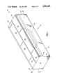
- FIG. 1 illustrates a perspective view of an air flotation bar, the present invention
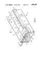
- FIG. 2 illustrates a partial cutaway view of the air bar header with the header end plate removed
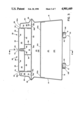
- FIG. 3 illustrates a cross-sectional view of the air flotation bar taken along line 3--3 of FIG. 2;
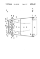
- FIG. 4 illustrates a partial front view and a partial cutaway view taken along line 4--4 of FIG. 3;
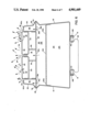
- FIG. 5 illustrates a view of FIG. 3 including the air flow in and about the air flotation bar
- FIG. 6 illustrates an alternative embodiment including air flow in and about an air flotation bar with negative pressure in the interior air bar channel members
- FIG. 7 illustrates an alternative embodiment in cross section of an air bar including air flow in and about the air flotation bar.
- FIG. 1 illustrates a perspective view of an air flotation bar 10 for use in a web dryer.
- Externally visible members in the figure illustrate the air flotation bar 10 including a channel like air bar header 12 with opposing canted sides 14 and 15, and a bottom 16.
- Opposing and parallel vertically aligned air bar header end plates 18 and 20 affix between the sides 14 and 15 with each end plate having an air bar alignment tab 22 and 24, as also illustrated in FIG. 4. Holes, slots or other various openings can be fabricated in the air bar alignment tabs 22 and 24 for securing, mounting or positioning of the air flotation bar 10 in a dryer.
- V channels 26 and 28 are formed in and aligned horizontally in sides 15 and 14, respectively, to accommodate air bar mounting flanges, as later described in detail.
- Air bars 30 and 32 align longitudinally in a precise manner between the upper regions of sides 14 and 15 longitudinally to form aligned Coanda slots 34, 36, and 38 as illustrated.
- Two outer Coanda slots 34 and 38 position as illustrated with an inner third Coanda slot 36 between air bars 30 and 32.
- An oval shaped air inlet 40 positions on the bottom 16 to accept dryer system air flow for the air flotation bar 10.
- FIG. 2 illustrates a partial cutaway view of the air flotation bar 10 with the air bar header end plate 18 removed for purposes of the illustration. All numerals correspond to those elements previously described. Reference to this FIG. and FIG. 3 also facilitates an understanding of the following disclosed subject matter.
- Air bars 30 and 32 are mirror images of each other, and position between the upper regions of sides 14 and 15. Air bar 32 includes an upper air bar channel member 42 and a lower air bar channel member 44 tightly secured and affixed within the upper air bar channel member 42 forming an air bar chamber.
- the upper air bar channel member 42 includes a horizontal planar surface 46, which intersects an inner vertical surface 48 to form a uniform defined radius Coanda curve 50, and also intersects an outer vertical surface 52 to form a uniform defined radius Coanda curve 54.
- the outer vertical surface 52 is bent at a right angle to form a horizontally aligned flange member 56 which in turn is accommodated by the V channel 26.
- the flange member 56 includes a plurality of holes 58a-58n where hole 58a and other like holes in the series are illustrated in the figure.
- a lip 60a of a sidewall 60 extends a finite distance inwardly at a right angle from the upper region of side 15 and on a plane lower than that of the horizontal planar surface 46 of the air bar 32 to form a Coanda slot 38 of a finite distance between the lip 60a and Coanda curve 54.
- An outer chamber 62 is also formed by the flange member 56, the upper portion of side 15, the outer vertical surface 52 and lip 60a.
- Air bar 30 is constructed in a like and similar manner to that of air bar 32, and includes a horizontal planar surface 66, an inner vertical surface 68, a Coanda curve 70, an outer vertical surface 72, a Coanda curve 74, a flange member 76, holes 78a-78n where only hole 78a and the other like holes in the series are illustrated, a lip 80a of sidewall 80 and an outer chamber 82.
- a support channel member 90 positions between the outer vertical surface 52 and outer vertical surface 72, and includes a plurality of orifices 92a-92n where only orifice 92a is illustrated.
- Vertically oriented struts 94 and 96 are positioned perpendicular on the support channel member 90 to support the inner ends of air bars 30 and 32, thus stabilizing the geometrical configuration of the inner Coanda slot 36 and forming outer support chambers 62 and 82.
- a central support chamber 91 is formed by struts 94 and 96, the support channel member 90, and the lower portions of the air bar channel members 44 and 64.
- a diffuser plate 100 including a plurality of holes 102a-102n secured between sides 14 and 15, and below the support channel member 90, provide for even flow of drying air from the oval shaped air inlet 40 of FIGS. 1 and 3.
- the diffuser plate 100, sides 14 and 15, air bar header end plates 18 and 20 of FIG. 1, and the bottom 16 define a first lower air flow chamber 104.
- the portions of the sides 14 and 15 just below the V channels 26 and 28, air bar header end plates 18 and 20, the support channel member 90 and the flange members 56 and 76 define a second upper diffused air flow chamber 106.
- An angled oval member 108 secures to the bottom 16 and adjacent to and about the oval shaped air inlet 40 to form a gasket chamber 111 about the oval shaped air inlet 40 as illustrated in FIG. 3.
- FIG. 3 illustrates a cross-sectional view of the present invention taken along line 3--3 of FIG. 2 where all numerals correspond to those elements previously described.
- FIG. 4 illustrates a partial front view and partial cutaway view taken along line 4--4 of FIG. 3 of the air flotation bar where all numerals correspond to those elements previously described.
- FIG. 5 illustrates a view of FIG. 3 with air flow in and about the air flotation bar 10 where all numerals correspond to those elements previously described.
- Dryer system air flows first through the oval shaped air inlet 40 and out of the Coanda slots 34, 36 and 38 as previously described. Air passing through the Coanda slots 34, 36, and 38, forms a broad air flow area to support a web. Air passing through the Coanda slot 36 projects and moves upwardly to, in effect, widen the distance between the flow of air flowing along towards the web and to provide a wider upper flow area beneath the web.
- the drying air flow has a wider foot print to provide a larger more effective drying area with heat transfer on the web.
- Dryer system air flow passes first through the oval shaped air inlet 40 of FIG. 3, through the first lower air flow chamber 104, through the diffuser plate 100 where the air flow is distributed evenly and diffused through the second upper diffused air flow chamber 106, and simultaneously through a plurality of holes 58a-58n, 78a-78n, and 92a-92n into chambers 62, 82, and 91, respectively.
- the diffuser plate straightens the air flow. Any other like structure which creates a pressure drop would act as a flow straightener.
- the air flow then continues from chambers 62, 82, and 91, and through Coanda slots 38, 34 and 36.
- each slot is about 0.035-0.2" by way of example and for purposes of illustration and not to be construed as limiting of the present invention, and in a range of preferably about 1.3-1.9% open area of the plane.
- the open area of the slots is in a range of 1-5% of the open area of the plane.
- FIG. 6 illustrates an alternative embodiment of the air flotation bar where all numerals correspond to those elements previously described. Negative pressure is applied to the interior chambers 110 and 112 of air bars 30 and 32 to create an area of low pressure in the areas of longitudinal holes 114 and 116, thus affecting air flow from the outer and inner Coanda slots 34 and 38, and 36, respectively, in the manner as illustrated by the air flow arrows.
- FIG. 7 illustrates an alternative embodiment in cross section of an air flotation bar 150 including sides 152 and 154, V channels 156 and 158, a diffuser plate 160 between sides 152 and 154, and a plurality of holes 162a-162n in the diffuser plate 160.
- a perforated support member 164 secures between the V channels 156 and 158. Longitudinal rows of perforations 166a-166d are in the perforated support member 164.
- a bottom 168 is between the sides 152 and 154.
- An oval shaped air inlet 170 locates on the bottom 168, and an angled oval member I71 forms a gasket chamber 175.
- U shaped channel member 176 and 178 secure to the perforated support member 164.
- the top portion of the U shaped channel members 176 and 178 extend above lips 152a and 154a of sides 152 and 154, respectively.
- the U shaped channel members 176 and 178 include a plurality of holes 181a-181n and 183a-183n extending longitudinally along the inner walls 180 and 182 of the U shaped channel members 176 and 178.
- a series of chambers 184, 192, 194 and 188 are formed in the upper regions of the air flotation bar 150 as now described in detail.
- a chamber 184 is formed by the upper portion of the side 152 above the V channel 156, lip 152a, the perforated support member 164, the outer wall 186 of the U shaped channel member 176, and ends 174 and 172.
- Chamber 188 is also formed by the upper portion of the side 154 above the V channel 156, lip 154a, the perforated support member 164, the outer wall 190 of the U shaped channel member 178, and ends 172 and 174.
- Chambers 192 and 194 are formed between U shaped channel members 176 and 178, the perforated support member 164, and ends 172 and 174.
- Coanda curves 196, 198, 200 and 202 are located at the corners of the U shaped channel members 176 and 178.
- Coanda slot 204 is formed by lip 152a and Coanda curve 196.
- Coanda slot 206 is formed by lip 154a and Coanda curve 202.
- Coanda slot 208 is formed between inner walls 180 and 182 and the Coanda curves 198 and 200.
- the lower chamber 212 is the region between sides 152 and 154 and ends 172 and 174 and beneath the diffuser plate 160.
- the upper chamber 214 is the area above the diffuser plate 160 bounded by the diffuser plate 160, sides 152 and 154, ends 172 and 174 and the perforated support member 164.
- Hole 166a is in common with chambers 184 and 192 and hole 166d are in common with chamber 194 and 188.
- Air passing through a plurality of holes 166a and 166d passes into chambers 184 and 188, divides and partially flows into chamber 192 and 194, respectively.
- the air flotation bar can be used for drying of printed webs, coated webs, or any other suitable air flotation applications.
Abstract
Description
Claims (35)
Priority Applications (5)
| Application Number | Priority Date | Filing Date | Title |
|---|---|---|---|
| US07/203,072 US4901449A (en) | 1988-06-07 | 1988-06-07 | Tri-flotation air bar |
| CA000601907A CA1337452C (en) | 1988-06-07 | 1989-06-06 | Tri-floatation air bar |
| DE68922245T DE68922245T2 (en) | 1988-06-07 | 1989-06-07 | Air box with three partial flows. |
| EP89305718A EP0346080B1 (en) | 1988-06-07 | 1989-06-07 | Tri-flotation air bar |
| JP1145047A JPH0722992B2 (en) | 1988-06-07 | 1989-06-07 | Air flotation bar |
Applications Claiming Priority (1)
| Application Number | Priority Date | Filing Date | Title |
|---|---|---|---|
| US07/203,072 US4901449A (en) | 1988-06-07 | 1988-06-07 | Tri-flotation air bar |
Publications (1)
| Publication Number | Publication Date |
|---|---|
| US4901449A true US4901449A (en) | 1990-02-20 |
Family
ID=22752373
Family Applications (1)
| Application Number | Title | Priority Date | Filing Date |
|---|---|---|---|
| US07/203,072 Expired - Lifetime US4901449A (en) | 1988-06-07 | 1988-06-07 | Tri-flotation air bar |
Country Status (5)
| Country | Link |
|---|---|
| US (1) | US4901449A (en) |
| EP (1) | EP0346080B1 (en) |
| JP (1) | JPH0722992B2 (en) |
| CA (1) | CA1337452C (en) |
| DE (1) | DE68922245T2 (en) |
Cited By (17)
| Publication number | Priority date | Publication date | Assignee | Title |
|---|---|---|---|---|
| US5064979A (en) * | 1990-08-07 | 1991-11-12 | W. R. Grace & Co.-Conn. | Microwave air float bar for drying a traveling web |
| US5105562A (en) * | 1990-12-26 | 1992-04-21 | Advance Systems, Inc. | Web dryer apparatus having ventilating and impingement air bar assemblies |
| US5150955A (en) * | 1990-12-28 | 1992-09-29 | Eastman Kodak Company | Drying apparatus |
| US5181329A (en) * | 1990-12-28 | 1993-01-26 | Eastman Kodak Company | Drying apparatus |
| US5293699A (en) * | 1991-08-21 | 1994-03-15 | Hoechst Aktiengesellschaft | Process and apparatus for guiding a coated material strip |
| US5590480A (en) * | 1994-12-06 | 1997-01-07 | W. R. Grace & Co.-Conn. | combination air bar and hole bar flotation dryer |
| US20050223593A1 (en) * | 2004-04-13 | 2005-10-13 | Rocheleau Michael O | Step air foil |
| US20060278360A1 (en) * | 2005-06-06 | 2006-12-14 | Solberg Bruce J | Vectored air web handling apparatus |
| US20070125876A1 (en) * | 2005-07-28 | 2007-06-07 | Ralf Bolling | Nozzle system for the treatment of web-shaped material |
| US20080276488A1 (en) * | 2007-05-07 | 2008-11-13 | Paul Seidl | Step air foil web stabilizer |
| US20100074707A1 (en) * | 2008-09-24 | 2010-03-25 | Hiroki Ikuta | Milling spindle of machine tool |
| US7694433B2 (en) | 2005-06-08 | 2010-04-13 | The Procter & Gamble Company | Web handling apparatus and process for providing steam to a web material |
| US20110131829A1 (en) * | 2009-06-05 | 2011-06-09 | Megtec Systems, Inc. | Infrared Float Bar |
| US8615899B2 (en) | 2008-08-27 | 2013-12-31 | Megtec Systems, Inc. | Paired air bar/hole bar arrangement in web dryer |
| DE102016205979A1 (en) | 2015-04-10 | 2016-10-13 | Megtec Systems, Inc. | Nozzles remote cover system |
| US20170350053A1 (en) * | 2014-12-17 | 2017-12-07 | Andritz Perfojet Sas | Water extraction facility |
| US11421374B2 (en) * | 2019-02-12 | 2022-08-23 | Samsung Electronics Co., Ltd. | Dryer |
Families Citing this family (6)
| Publication number | Priority date | Publication date | Assignee | Title |
|---|---|---|---|---|
| CH679931A5 (en) * | 1990-04-18 | 1992-05-15 | Brandwijk Systems Programming | |
| US6293196B1 (en) * | 1993-10-06 | 2001-09-25 | Howard W. DeMoore | High velocity, hot air dryer and extractor |
| DE19607397A1 (en) * | 1996-02-28 | 1997-09-04 | Heidelberger Druckmasch Ag | Device and method for guiding sheet material in a printing press, in particular in a sheet-fed offset printing press |
| ATE274030T1 (en) * | 1996-06-05 | 2004-09-15 | Atofina | FLEXIBLE THERMOPLASTIC RESINS WITH IMPROVED TENSILE STRENGTH |
| FR2790072B1 (en) * | 1999-02-18 | 2001-05-25 | Solaronics Process | COMBINED BLOW AND SUCTION DEVICE WITH INTEGRATED ENERGY EXCHANGE FOR A DRYING DEVICE |
| US8083896B2 (en) * | 2008-09-26 | 2011-12-27 | Honeywell Asca Inc. | Pressure equalizing baffle and coanda air clamp |
Citations (17)
| Publication number | Priority date | Publication date | Assignee | Title |
|---|---|---|---|---|
| US2492974A (en) * | 1946-04-30 | 1950-01-03 | Dungler Julien | Nozzle member used for the drying of textile and other materials |
| US3198499A (en) * | 1961-08-11 | 1965-08-03 | Kaiser Aluminium Chem Corp | Method and apparatus for supporting and heat treating |
| CA768851A (en) * | 1967-10-10 | Kalle Aktiengesellschaft | Treatment of material in web form | |
| US3672066A (en) * | 1970-10-30 | 1972-06-27 | Bechtel Int Corp | Microwave drying apparatus |
| US3827639A (en) * | 1972-01-04 | 1974-08-06 | J Relue | Drying chamber apparatus |
| US3873013A (en) * | 1973-10-04 | 1975-03-25 | Tec Systems | High velocity web floating air bar having center exhaust means |
| US3982327A (en) * | 1975-05-01 | 1976-09-28 | Midland-Ross Corporation | Air-dispensing web-floating apparatus |
| US4137644A (en) * | 1975-12-09 | 1979-02-06 | Aktiebolaget Svenska Flaktfabriken | Treating airborne web material |
| US4197973A (en) * | 1978-10-12 | 1980-04-15 | W. R. Grace & Co. | High velocity web floating air bar having air flow straightening means for air discharge slot means |
| US4197971A (en) * | 1978-10-12 | 1980-04-15 | W. R. Grace & Co. | High velocity web floating air bar having an internal passage for transverse air discharge slot means |
| US4201323A (en) * | 1978-10-12 | 1980-05-06 | W. R. Grace & Co. | High velocity web floating air bar having a recessed Coanda plate |
| US4265384A (en) * | 1980-01-21 | 1981-05-05 | W. R. Grace & Co. | Air bar having asymmetrical inlet |
| US4274210A (en) * | 1978-09-11 | 1981-06-23 | Valmet Oy | Gas nozzle for use in treating material webs |
| US4292745A (en) * | 1978-08-29 | 1981-10-06 | Caratsch Hans Peter | Air foil nozzle dryer |
| US4425719A (en) * | 1982-03-15 | 1984-01-17 | W. R. Grace & Co. | Compact air bar assembly for contactless web support |
| US4472888A (en) * | 1982-06-04 | 1984-09-25 | Cary Metal Products, Inc. | Coanda effect nozzle for handling continuous webs |
| US4768695A (en) * | 1987-06-11 | 1988-09-06 | Advance Systems, Inc. | Air bar for paper web handling apparatus and having an air distributing chamber and perforated plate therefor |
Family Cites Families (5)
| Publication number | Priority date | Publication date | Assignee | Title |
|---|---|---|---|---|
| US3549070A (en) * | 1969-02-27 | 1970-12-22 | Tec Systems | Floatation of sheet materials |
| EP0003414B1 (en) * | 1978-01-27 | 1981-11-04 | Spooner Edmeston Engineering Limited | Float treatment apparatus |
| GB2058313A (en) * | 1979-08-24 | 1981-04-08 | Caratsch Hans Peter | Air foil nozzle dryer |
| GB2126974B (en) * | 1982-09-07 | 1985-09-11 | Grace W R & Co | Device for supporting a web on a bed of air |
| GB2146303B (en) * | 1983-08-20 | 1987-01-14 | Spooner Ind Ltd | Device for supporting web on a bed of air |
-
1988
- 1988-06-07 US US07/203,072 patent/US4901449A/en not_active Expired - Lifetime
-
1989
- 1989-06-06 CA CA000601907A patent/CA1337452C/en not_active Expired - Fee Related
- 1989-06-07 JP JP1145047A patent/JPH0722992B2/en not_active Expired - Fee Related
- 1989-06-07 EP EP89305718A patent/EP0346080B1/en not_active Expired - Lifetime
- 1989-06-07 DE DE68922245T patent/DE68922245T2/en not_active Expired - Fee Related
Patent Citations (17)
| Publication number | Priority date | Publication date | Assignee | Title |
|---|---|---|---|---|
| CA768851A (en) * | 1967-10-10 | Kalle Aktiengesellschaft | Treatment of material in web form | |
| US2492974A (en) * | 1946-04-30 | 1950-01-03 | Dungler Julien | Nozzle member used for the drying of textile and other materials |
| US3198499A (en) * | 1961-08-11 | 1965-08-03 | Kaiser Aluminium Chem Corp | Method and apparatus for supporting and heat treating |
| US3672066A (en) * | 1970-10-30 | 1972-06-27 | Bechtel Int Corp | Microwave drying apparatus |
| US3827639A (en) * | 1972-01-04 | 1974-08-06 | J Relue | Drying chamber apparatus |
| US3873013A (en) * | 1973-10-04 | 1975-03-25 | Tec Systems | High velocity web floating air bar having center exhaust means |
| US3982327A (en) * | 1975-05-01 | 1976-09-28 | Midland-Ross Corporation | Air-dispensing web-floating apparatus |
| US4137644A (en) * | 1975-12-09 | 1979-02-06 | Aktiebolaget Svenska Flaktfabriken | Treating airborne web material |
| US4292745A (en) * | 1978-08-29 | 1981-10-06 | Caratsch Hans Peter | Air foil nozzle dryer |
| US4274210A (en) * | 1978-09-11 | 1981-06-23 | Valmet Oy | Gas nozzle for use in treating material webs |
| US4201323A (en) * | 1978-10-12 | 1980-05-06 | W. R. Grace & Co. | High velocity web floating air bar having a recessed Coanda plate |
| US4197971A (en) * | 1978-10-12 | 1980-04-15 | W. R. Grace & Co. | High velocity web floating air bar having an internal passage for transverse air discharge slot means |
| US4197973A (en) * | 1978-10-12 | 1980-04-15 | W. R. Grace & Co. | High velocity web floating air bar having air flow straightening means for air discharge slot means |
| US4265384A (en) * | 1980-01-21 | 1981-05-05 | W. R. Grace & Co. | Air bar having asymmetrical inlet |
| US4425719A (en) * | 1982-03-15 | 1984-01-17 | W. R. Grace & Co. | Compact air bar assembly for contactless web support |
| US4472888A (en) * | 1982-06-04 | 1984-09-25 | Cary Metal Products, Inc. | Coanda effect nozzle for handling continuous webs |
| US4768695A (en) * | 1987-06-11 | 1988-09-06 | Advance Systems, Inc. | Air bar for paper web handling apparatus and having an air distributing chamber and perforated plate therefor |
Cited By (27)
| Publication number | Priority date | Publication date | Assignee | Title |
|---|---|---|---|---|
| US5064979A (en) * | 1990-08-07 | 1991-11-12 | W. R. Grace & Co.-Conn. | Microwave air float bar for drying a traveling web |
| US5105562A (en) * | 1990-12-26 | 1992-04-21 | Advance Systems, Inc. | Web dryer apparatus having ventilating and impingement air bar assemblies |
| US5150955A (en) * | 1990-12-28 | 1992-09-29 | Eastman Kodak Company | Drying apparatus |
| US5181329A (en) * | 1990-12-28 | 1993-01-26 | Eastman Kodak Company | Drying apparatus |
| US5293699A (en) * | 1991-08-21 | 1994-03-15 | Hoechst Aktiengesellschaft | Process and apparatus for guiding a coated material strip |
| US5590480A (en) * | 1994-12-06 | 1997-01-07 | W. R. Grace & Co.-Conn. | combination air bar and hole bar flotation dryer |
| US7530179B2 (en) * | 2004-04-13 | 2009-05-12 | Megtec Systems, Inc. | Step air foil |
| US20050223593A1 (en) * | 2004-04-13 | 2005-10-13 | Rocheleau Michael O | Step air foil |
| WO2005103592A1 (en) * | 2004-04-13 | 2005-11-03 | Megtec Systems, Inc. | Step air foil |
| US20060278360A1 (en) * | 2005-06-06 | 2006-12-14 | Solberg Bruce J | Vectored air web handling apparatus |
| US7311234B2 (en) | 2005-06-06 | 2007-12-25 | The Procter & Gamble Company | Vectored air web handling apparatus |
| US7694433B2 (en) | 2005-06-08 | 2010-04-13 | The Procter & Gamble Company | Web handling apparatus and process for providing steam to a web material |
| US20070125876A1 (en) * | 2005-07-28 | 2007-06-07 | Ralf Bolling | Nozzle system for the treatment of web-shaped material |
| US8061055B2 (en) | 2007-05-07 | 2011-11-22 | Megtec Systems, Inc. | Step air foil web stabilizer |
| US20080276488A1 (en) * | 2007-05-07 | 2008-11-13 | Paul Seidl | Step air foil web stabilizer |
| US8615899B2 (en) | 2008-08-27 | 2013-12-31 | Megtec Systems, Inc. | Paired air bar/hole bar arrangement in web dryer |
| US20100074707A1 (en) * | 2008-09-24 | 2010-03-25 | Hiroki Ikuta | Milling spindle of machine tool |
| US20110131829A1 (en) * | 2009-06-05 | 2011-06-09 | Megtec Systems, Inc. | Infrared Float Bar |
| US9228779B2 (en) | 2009-06-05 | 2016-01-05 | Megtec Systems, Inc. | Infrared float bar |
| US9746235B2 (en) | 2009-06-05 | 2017-08-29 | Megtec Systems, Inc. | Infrared float bar |
| US10139159B2 (en) | 2009-06-05 | 2018-11-27 | Babcock & Wilcox Megtec, Llc | Infrared float bar |
| US10371443B2 (en) | 2009-06-05 | 2019-08-06 | Durr Megtec, Llc | Infrared float bar |
| US20170350053A1 (en) * | 2014-12-17 | 2017-12-07 | Andritz Perfojet Sas | Water extraction facility |
| US10487430B2 (en) * | 2014-12-17 | 2019-11-26 | Andritz Perfojet Sas | Water extraction facility |
| DE102016205979A1 (en) | 2015-04-10 | 2016-10-13 | Megtec Systems, Inc. | Nozzles remote cover system |
| US10598433B2 (en) | 2015-04-10 | 2020-03-24 | Durr Systems, Inc. | Remote nozzle deckle system |
| US11421374B2 (en) * | 2019-02-12 | 2022-08-23 | Samsung Electronics Co., Ltd. | Dryer |
Also Published As
| Publication number | Publication date |
|---|---|
| JPH0722992B2 (en) | 1995-03-15 |
| DE68922245D1 (en) | 1995-05-24 |
| EP0346080A1 (en) | 1989-12-13 |
| CA1337452C (en) | 1995-10-31 |
| DE68922245T2 (en) | 1995-11-09 |
| JPH0225334A (en) | 1990-01-26 |
| EP0346080B1 (en) | 1995-04-19 |
Similar Documents
| Publication | Publication Date | Title |
|---|---|---|
| US4901449A (en) | Tri-flotation air bar | |
| MY109767A (en) | Moulded baffle heat exchanger | |
| US4785986A (en) | Paper web handling apparatus having improved air bar with dimensional optimization | |
| FI73820B (en) | ANORDNING FOER VAERMEBEHANDLING AV FLATA, BANFORMIGA MATERIALBANOR. | |
| US3873013A (en) | High velocity web floating air bar having center exhaust means | |
| US5092059A (en) | Infrared air float bar | |
| EP0096532A2 (en) | Improved coanda effect nozzle for handling continuous webs | |
| DK0460323T3 (en) | Biological sterilization test pack | |
| GB2025020A (en) | Air dryer nozzle | |
| US3800438A (en) | Apparatus for treatment of materials, particularly the heat treatment of webs | |
| CA2094795C (en) | Trailing sheet assembly for an air turn | |
| US3525164A (en) | Apparatus for gaseous treatment of moving webs | |
| US3599341A (en) | Method and apparatus for drying a web | |
| US3739490A (en) | Orifice pattern for jet dryers | |
| US4341024A (en) | Tube dryer assembly | |
| GB2205932A (en) | Paper drying air bar | |
| GB2126974A (en) | Device for supporting a web on a bed of air | |
| GB2070461A (en) | Apparatus for blowing a gaseous treatment medium onto a length of material | |
| GB2142216A (en) | Apparatus for storing and ventilating cheeses | |
| CA1105699A (en) | Arrangement in drying plant for preferably air-borne web | |
| JP3732229B2 (en) | Blow box used in plant for drying raw web | |
| US5125170A (en) | Flotation dryer nozzle | |
| US5035066A (en) | Ultraviolet air floatation bar | |
| EP0346081A1 (en) | Air float bar | |
| US5024004A (en) | Radio frequency air float bar |
Legal Events
| Date | Code | Title | Description |
|---|---|---|---|
| AS | Assignment |
Owner name: W. R. GRACE & CO., 55 HAYDEN AVENUE, LEXINGTON, MA Free format text: ASSIGNMENT OF ASSIGNORS INTEREST.;ASSIGNOR:WIMBERGER, RICHARD J.;REEL/FRAME:004894/0200 Effective date: 19880602 Owner name: W. R. GRACE & CO., MASSACHUSETTS Free format text: ASSIGNMENT OF ASSIGNORS INTEREST;ASSIGNOR:WIMBERGER, RICHARD J.;REEL/FRAME:004894/0200 Effective date: 19880602 |
|
| AS | Assignment |
Owner name: W. R. GRACE & CO. -CONN., A CORP. OF CT, NEW YORK Free format text: ASSIGNMENT OF ASSIGNORS INTEREST.;ASSIGNORS:WIMBERGER, RICHARD J.;MORAN, KENNETH J.;ROCHELEAU, MICHAEL O.;REEL/FRAME:005221/0032 Effective date: 19890525 Owner name: W. R. GRACE & CO.-CONN., NEW YORK Free format text: TO CORRECT THE NAME OF THE ASSIGNEE IN AN ASSIGNMENT PREVIOUSLY RECORDED AT REEL 4894 FRAME 200 ON JUNE 7, 1988, ASSIGNOR HEREBY ASSIGNS HIS ENTIRE INTEREST IN SAID PATENT TO SAID ASSIGNEE;ASSIGNOR:WIMBERGER, RICHARD J.;REEL/FRAME:005237/0078 Effective date: 19890525 |
|
| STCF | Information on status: patent grant |
Free format text: PATENTED CASE |
|
| FPAY | Fee payment |
Year of fee payment: 4 |
|
| FPAY | Fee payment |
Year of fee payment: 8 |
|
| AS | Assignment |
Owner name: THERMAL EMISSION CONTROL SYSTEMS, INC., WISCONSIN Free format text: ASSIGNMENT OF ASSIGNORS INTEREST;ASSIGNOR:W.R. GRACE & CO.-CONN.;REEL/FRAME:008820/0146 Effective date: 19970829 Owner name: MEGTEC SYSTEMS, INC., WISCONSIN Free format text: CHANGE OF NAME;ASSIGNOR:THERMAL EMISSION CONTROL SYSTEMS, INC.;REEL/FRAME:008820/0239 Effective date: 19970909 |
|
| FEPP | Fee payment procedure |
Free format text: PAYOR NUMBER ASSIGNED (ORIGINAL EVENT CODE: ASPN); ENTITY STATUS OF PATENT OWNER: LARGE ENTITY |
|
| FPAY | Fee payment |
Year of fee payment: 12 |
|
| AS | Assignment |
Owner name: LEHMAN COMMERCIAL PAPER, INC., NEW YORK Free format text: GUARANTEE AND COLLATERAL AGREEMENT;ASSIGNOR:MEGTEC SYSTEMS, INC.;REEL/FRAME:020525/0827 Effective date: 20071203 |
|
| AS | Assignment |
Owner name: LEHMAN COMMERCIAL PAPER, INC., NEW YORK Free format text: CORRECTIVE ASSIGNMENT TO CORRECT THE PATENT NOS. 4901419, 5709542 AND 6795883 PREVIOUSLY RECORDED ON REEL 020525 FRAME 0827. ASSIGNOR(S) HEREBY CONFIRMS THE GUARANTEE AND COLLATERAL AGREEMENT.;ASSIGNOR:MEGTEC SYSTEMS, INC.;REEL/FRAME:020571/0001 Effective date: 20071203 |
|
| AS | Assignment |
Owner name: SEQUA GMBH & CO., WISCONSIN Free format text: RELEASED BY SECURED PARTY;ASSIGNOR:LEHMAN COMMERCIAL PAPER, INC.;REEL/FRAME:021630/0602 Effective date: 20080924 Owner name: MTS ASIA, INC., WISCONSIN Free format text: RELEASED BY SECURED PARTY;ASSIGNOR:LEHMAN COMMERCIAL PAPER, INC.;REEL/FRAME:021630/0602 Effective date: 20080924 Owner name: MEGTEC SYSTEMS AB, WISCONSIN Free format text: RELEASED BY SECURED PARTY;ASSIGNOR:LEHMAN COMMERCIAL PAPER, INC.;REEL/FRAME:021630/0602 Effective date: 20080924 Owner name: MEGTEC SYSTEMS, INC., WISCONSIN Free format text: RELEASED BY SECURED PARTY;ASSIGNOR:LEHMAN COMMERCIAL PAPER, INC.;REEL/FRAME:021630/0602 Effective date: 20080924 Owner name: MEGTEC SYSTEMS AUSTRALIA, INC., WISCONSIN Free format text: RELEASED BY SECURED PARTY;ASSIGNOR:LEHMAN COMMERCIAL PAPER, INC.;REEL/FRAME:021630/0602 Effective date: 20080924 Owner name: MEGTEC SYSTEMS KG, WISCONSIN Free format text: RELEASED BY SECURED PARTY;ASSIGNOR:LEHMAN COMMERCIAL PAPER, INC.;REEL/FRAME:021630/0602 Effective date: 20080924 Owner name: MEGTEC SYSTEMS, S.A.S., WISCONSIN Free format text: RELEASED BY SECURED PARTY;ASSIGNOR:LEHMAN COMMERCIAL PAPER, INC.;REEL/FRAME:021630/0602 Effective date: 20080924 Owner name: MEGTEC SYSTEMS AMAL AB, WISCONSIN Free format text: RELEASED BY SECURED PARTY;ASSIGNOR:LEHMAN COMMERCIAL PAPER, INC.;REEL/FRAME:021630/0602 Effective date: 20080924 |
|
| AS | Assignment |
Owner name: MEGTEC SYSTEMS, INC., WISCONSIN Free format text: TERMINATION OF SECURITY INTEREST IN PATENTS AT REEL/FRAME NOS. 20525/0827 AND 20571/0001;ASSIGNOR:LEHMAN COMMERCIAL PAPER, INC.;REEL/FRAME:021617/0548 Effective date: 20080924 |
|
| AS | Assignment |
Owner name: BANK OF AMERICA, N.A., AS ADMINISTRATIVE AGENT, NO Free format text: SECURITY AGREEMENT;ASSIGNOR:MEGTEC SYSTEMS, INC.;REEL/FRAME:021719/0141 Effective date: 20080924 |
|
| AS | Assignment |
Owner name: MEGTEC SYSTEMS, INC., WISCONSIN Free format text: TERMINATION AND RELEASE OF SECURITY INTEREST IN PATENT AND TRADEMARK RIGHTS;ASSIGNOR:BANK OF AMERICA, N.A., AS ADMINISTRATIVE AGENT;REEL/FRAME:027430/0112 Effective date: 20111216 |