US4901461A - House identification fixture - Google Patents
House identification fixture Download PDFInfo
- Publication number
- US4901461A US4901461A US07/142,513 US14251388A US4901461A US 4901461 A US4901461 A US 4901461A US 14251388 A US14251388 A US 14251388A US 4901461 A US4901461 A US 4901461A
- Authority
- US
- United States
- Prior art keywords
- display unit
- power pack
- light
- illuminating
- house
- Prior art date
- Legal status (The legal status is an assumption and is not a legal conclusion. Google has not performed a legal analysis and makes no representation as to the accuracy of the status listed.)
- Expired - Fee Related
Links
Images
Classifications
-
- G—PHYSICS
- G09—EDUCATION; CRYPTOGRAPHY; DISPLAY; ADVERTISING; SEALS
- G09F—DISPLAYING; ADVERTISING; SIGNS; LABELS OR NAME-PLATES; SEALS
- G09F13/00—Illuminated signs; Luminous advertising
- G09F13/04—Signs, boards or panels, illuminated from behind the insignia
-
- G—PHYSICS
- G09—EDUCATION; CRYPTOGRAPHY; DISPLAY; ADVERTISING; SEALS
- G09F—DISPLAYING; ADVERTISING; SIGNS; LABELS OR NAME-PLATES; SEALS
- G09F13/00—Illuminated signs; Luminous advertising
- G09F13/04—Signs, boards or panels, illuminated from behind the insignia
- G09F13/0418—Constructional details
- G09F13/045—Signs, boards or panels specially adapted for doors
-
- Y—GENERAL TAGGING OF NEW TECHNOLOGICAL DEVELOPMENTS; GENERAL TAGGING OF CROSS-SECTIONAL TECHNOLOGIES SPANNING OVER SEVERAL SECTIONS OF THE IPC; TECHNICAL SUBJECTS COVERED BY FORMER USPC CROSS-REFERENCE ART COLLECTIONS [XRACs] AND DIGESTS
- Y10—TECHNICAL SUBJECTS COVERED BY FORMER USPC
- Y10S—TECHNICAL SUBJECTS COVERED BY FORMER USPC CROSS-REFERENCE ART COLLECTIONS [XRACs] AND DIGESTS
- Y10S40/00—Card, picture, or sign exhibiting
- Y10S40/902—Circuit control, e.g. flashing light
Definitions
- This invention relates to illumination devices, and more particularly to devices for illuminating a house identifier, number, or other information or messages, and to facilitate observation of them from the street.
- House numbers and the like are generally attached on, above, or in the vicinity of the front door of a house. Very often, however, house numbers are difficult to see from a distance or from a passing vehicle. The number may be hidden, missing, or broken. Moreover, at night, even a prominent house identification number, when not illuminated, is difficult or impossible to see. In addition, emergency service persons such as ambulance drivers or policemen often lose precious minutes in identifying the proper home during an emergency.
- the invention addresses the problem of house identification by providing a novel, multi-mode of control illuminated house numbering fixture.
- the identification fixture is visible from a distance both day and night, fulfilling the above-noted need to identify one's home. It enables local emergency organizations to find the home and provide the needed help without delay.
- An efficient and economical device has a capacity for multi-modal operation including manual control, automatic control, override, blinking white, and blinking red modes.
- the present invention provides an ease of installation and bulb replacement, a capacity for external actuation (e.g. smoke alarm), and bulb and battery back-up and testing systems.
- the present device include the capacity for communicating messages to a viewer.
- the house identification device disclosed herein overcomes a longstanding problem providing a versatile and efficient identification system.
- the modular design of the invention provides for a high level of installation flexibility which enables a substantial modification of the product to fit user needs, without requiring reflectors.
- the modular construction lends itself to computerized control and use with alternative power sources. For example, in an emergency, such as during a power failure, the inventive device may be plugged into an auto battery.
- the invention can be post-mounted or secured directly to a building. No reflectors are needed to amplify the light sources, even if some bulbs fail.
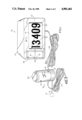
- FIG. 1 illustrates a perspective view of the present invention including the transformer and the display apparatus.
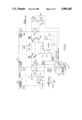
- FIG. 2 is a schematic diagram of a circuit for controlling the lighting of the display apparatus.
- FIG. 1 provides a perspective view of the present invention. Two embodiments of the present invention are contemplated, a device having automatic features and a device without those features.
- the automatic embodiment conforms to FIG. 1, while the manual device is substantially identical, but does not have certain of the control features
- the automatic device as compared to the manual device is further discussed below.
- Display unit 10 includes a housing 12, a window 14, identification numbers 16, and message window 18.
- Housing 12 is preferably approximately 7 inches high, 11.5 inches wide and 3 inches deep.
- Numbers 16 are mounted on a white translucent light panel 20 which is preferably attached to housing 12 by "Velcro" brand hook and loop fastener strips 22 and 24, for example.
- the "Velcro" strips hold the translucent light panel 20 on housing 12 while providing for ease of removal and replacement of bulbs.
- a preferred embodiment of this invention is capable of displaying any suitable indicia, such as six numbers and a hyphen or a letter, or no numbers, just a name, or any other suitable symbols.
- An optional message window 26 may provide an outdoor message, if desired, for an arriving emergency service person, e.g. to warn a policeman that a burglar has a gun. This message may be encoded, if desired, as illustrated by code symbols.
- the entire housing is made of a white translucent ABS plastic to give the light emanating from it and the entire unit an aura.
- a housing constructed of white translucent ABS plastic will extend the illumination beyond the housing walls to about a distance of 2 feet on all sides, producing an illuminated area of approximately 16 square feet around the housing.
- This same housing in combination with low voltage, permits high illumination without excessive heat build up, the use of light reflectors, or high voltage bulbs. This will increase the probability that the unit and its displayed house number or other information is quickly and distantly sighted.
- Electrical cord 28 extends from display unit 10 to combined control module and power pack 30.
- Cord 28 is generally run from the outdoor unit 10 into the house for enabling a convenient remote control of the display unit.
- Cord 28 attaches to transformer and power pack section 32 of control module and power pack 30.
- the power pack may include multiple indicator light 34 to signal the homeowner when the display unit is switched on and in operation.
- a fuse 36 may also be provided.
- a cover 38 may be easily removed to facilitate installation and maintenance of the electrical connection and circuitry.
- Section 41 includes a control module which is shown in FIG. 2
- a multiposition control switch 40 controls the display unit and includes settings for an off/on position, manual operation, automatic operation, blinking red, and blinking white displays.
- the automatic operation position the display unit automatically turns itself on and off, as at dusk and dawn, for example.
- the manual switch position bypasses and overrides the automatic controller so that the user can operate the display device at will.
- the control switch 40 is in the blink white position the light panel 20 is caused to blink with normal white light, enabling an identification of the home. White light blinking would most often be used if a friend, repairman, delivery man, or the like is expected.
- the blink red position light panel 20 is caused to blink with a red light. It is contemplated that the blink red switch will be used to identify the home to an ambulance operator, policeman or the like. An optional audible alarm may also be installed to function when this position is selected.
- the display unit may also be controlled by a remote sensor 77, such as a smoke alarm, for example, via a cord 43.
- a remote sensor 77 such as a smoke alarm, for example, via a cord 43.
- Other remote sensors may be a burglar alarm or a cold temperature sensor signal, which are operable even if the display unit is in an off position.
- Power pack 30 has a cord 42, with a plug 44, extending from transformer portion 32 to a 110 volt AC wall socket.
- a battery back up system may also be provided in conjunction with control module/power pack 30.
- a non-flutter circuit is provided to assure operational quality of the display unit. Duplicate bulbs are included in each circuit to ensure that if one bulb fails the others will still provide enough illumination to make the house number readable. When control switch 40 is in the blink red or blink white positions, indicator light 34 also blinks unless both of the duplicate bulbs are burned out, in which case indicator light 34 may remain unlit.
- the display unit 10 is generally located on the exterior of a house. It may be quickly attached to an outside wall of a dwelling by using two or four screws which penetrate the back of the light panel cavity. Access to these holes is accomplished by gently bending inwardly the translucent light panel 20 with the eraser end of a pencil and pulling outward. The light panel cover should pop out with a minimum of effort.
- the cord 28 from the power pack to housing 12 is preferably the same kind of wire that is used as a telephone extension cord. Display unit 10 may also be placed in the interior window of a house if desired.
- FIG. 2 shows the circuit which controls the lighting of the display and which is preferably housed within the control module/power pack 30 (FIG. 1).
- the principal elements of FIG. 2 are a lamp field 60, a light sensing photo resistor 62, a timer 64, and a number of transistors.
- the timer 64 may be any suitable device.
- One embodiment used a standard CMOS integrated circuit timer 555 manufactured by the Sprague Electric Company of New Hampshire. This timer 64 may be adapted to switch the lamp bulbs 60 either off and on or between bright and dim levels of illumination.
- the advantage of a bright-dim operation is that the filaments have a lifetime which is longer than it would be if the lamps are switched on and off.
- the disadvantage of bright-dim operation is that it may be less attention getting than on/off operation.
- the switch 40 may be manually moved to any one of five different steps or positions A-E. On switch step or position A, the circuit is switched off. However, an option is provided by which a remote sensor may control the emergency lighting of the lamps even while the switch is in any position, including off.
- a wire is normally connected across terminals 70, 72 and another wire is connected across terminals 74, 76. If it is desirable, any suitable remote sensor 77 (such as a smoke detector, for example) may be connected across terminals 78, 80, in which case the wire is removed at 74, 76.
- This remote sensor should have normally closed contacts, in simulation of the wire connected via wire 43 across terminals 74, 76, which contacts are opened when the sensed condition occurs.
- the remote sensor may override the "off" switch step or position A and turn on the light. If the wire is left in place at terminals 70, 72, there is no effect if the remote sensor opens its contacts while switch 40 is on step A.
- ground 82 is applied over a wire directly to the filament of the clear bulbs 66 to give a steady white light. This same ground is applied to a cathode of a yellow LED 34a to give a visual signal at 34 in FIG. 1.
- the anode of LED 34a is connected through a bias resistor 84, to battery V+.
- switch 40 applies ground 82 to the emitter and through transistor 86, LED 34a, and bias resistor 84 to battery V+.
- the timer 64 cyclically applies an "on" bias through a coupling resistor 88 to the base of transistor 86. Depending upon the timer, this bias voltage switches the transistor 86 either on and off to blink the lights or between high and low to give a bright-dim lamp operation.
- the lamp current is over the path from ground 82, through switch 40 on step C, transistor 86, and clear lamps 66 to V+ battery.
- the LED 34a blinks as transistor 86 switches on/off (or high/low).
- step D switch 40 applies ground 82 to the emitter of a transistor 90 which operates exactly the same as transistor 86 operates under the influence of timer 64 and via coupling resistor 65. This time the red lamps 68 are lit over the path from ground 82, through switch 40 on step D, transistor 90, and the filaments of red lamps 68 to battery V+. The red LED 34b flashes as the timer 64 switches transistor 90 on/off (high/low).
- Transistor 94 is controlled by the remote sensor 77.
- the emitter of transistor 94 is biased to ground via diode 95, the collector to battery V+ via LED 34b and resistor 84.
- Normally ground 82 is always applied to diode 96 either through a wire connected across terminals 74, 76 or through normally closed contacts in sensor 77. This ground 82 always clamps the base of transistor 94 in an off condition. If the remote sensor 77 reacts to an emergency condition (smoke is detected, for example), the contacts across terminals 78, 80 are opened. The clamping ground 82 is removed from the cathode of diode 96.
- the timer 64 switches on/off (high/low) in response to bias applied to transistor 94 via resistor 98.
- the red lamps 68 light over the path from ground at diode 95 through transistor 94 and, lamps 68 to battery V+.
- the LED 34b also lights through resistor 84 to battery V+.
- step E the display is automatically lit when the ambient light drops below a threshold value, as at dusk, for example.
- ground 82 is applied over switch 40 on step E, to the emitters of transistors 100, 102.
- the collector of driver transistor 100 is supplied from battery V+ via load resistor 104.
- the collector of transistor 102 is supplied from battery V+ via the load of clear light bulbs 66, and via resistor 84 and LED 34a.
- the collector of driver 100 is connected to the base of transistor 102.
- the potential on the base of transistor 100 is controlled from photoresistor 62.
- photoresistor 62 When photoresistor 62 is in the presence of light, the voltage applied from battery V+ through the photoresistor 62 and coupling resistor 108 clamps transistor 100 in an off condition and transistor 100 remains off.
- the resistance of photoresistor 62 increases as photoactivity in the resistor decreases.
- the bias voltage applied through resistors 106, 108 to the base of the transistor 100 changes to switch it on.
- the solid state circuit (FIG. 2) is unique to this field of home products.
- Most low voltage circuits in homes (such as doorbells and furnace controls, for example) use 16 V AC circuits.
- the 110 V or 16 V AC circuits are pulsed by the crude interrupters used in this field, they produce significant radio frequency levels which would likely be heard on home radios.
- the use of DC enables the circuit of FIG. 2 to operate from noise-free, easily rechargeable battery backup power supplies.
- These DC circuits enable an easy inclusion of the inventive system into a message center's microcomputer.
- the "blink rate" is easily changed by changing values in a resistor-capacitor circuit.
Abstract
Description
Claims (12)
Priority Applications (1)
| Application Number | Priority Date | Filing Date | Title |
|---|---|---|---|
| US07/142,513 US4901461A (en) | 1985-09-25 | 1988-01-11 | House identification fixture |
Applications Claiming Priority (2)
| Application Number | Priority Date | Filing Date | Title |
|---|---|---|---|
| US77980985A | 1985-09-25 | 1985-09-25 | |
| US07/142,513 US4901461A (en) | 1985-09-25 | 1988-01-11 | House identification fixture |
Related Parent Applications (1)
| Application Number | Title | Priority Date | Filing Date |
|---|---|---|---|
| US77980985A Continuation-In-Part | 1985-09-25 | 1985-09-25 |
Publications (1)
| Publication Number | Publication Date |
|---|---|
| US4901461A true US4901461A (en) | 1990-02-20 |
Family
ID=26840162
Family Applications (1)
| Application Number | Title | Priority Date | Filing Date |
|---|---|---|---|
| US07/142,513 Expired - Fee Related US4901461A (en) | 1985-09-25 | 1988-01-11 | House identification fixture |
Country Status (1)
| Country | Link |
|---|---|
| US (1) | US4901461A (en) |
Cited By (48)
| Publication number | Priority date | Publication date | Assignee | Title |
|---|---|---|---|---|
| US5036443A (en) * | 1990-05-02 | 1991-07-30 | Wayne Humble | Proximity light |
| WO1992013474A1 (en) * | 1991-02-08 | 1992-08-20 | Mcmanigal Paul G | Artificial window apparatus |
| US5172347A (en) * | 1988-12-15 | 1992-12-15 | Nihonkenkozoshinkenkyukai Co., Ltd. | Time displaying apparatus |
| US5251392A (en) * | 1991-02-08 | 1993-10-12 | Vemco Corporation | Artificial window |
| US5270698A (en) * | 1990-12-03 | 1993-12-14 | Hoyle Patrick D | Emergency signaling device |
| US5349241A (en) * | 1992-10-13 | 1994-09-20 | Cpx Industries, Inc. | Multiple point controlled flashing locator system |
| US5367808A (en) * | 1993-03-25 | 1994-11-29 | Decora Industry, Inc. | Low power-consumption sign-turner |
| US5406129A (en) * | 1992-10-13 | 1995-04-11 | Cpx Industries, Inc. | Flashing locator switch control with built-in lamp operation test |
| US5408773A (en) * | 1994-03-08 | 1995-04-25 | Hwang; Steven | House number plate and lamp assembly |
| US5408771A (en) * | 1993-09-27 | 1995-04-25 | Manrubia; Bob | Lighted box frame with 3-dimensional matting |
| GB2293678A (en) * | 1994-09-27 | 1996-04-03 | Hill Kenneth William George | Illuminated house signs |
| US5521578A (en) * | 1991-01-31 | 1996-05-28 | Delvalle; Ivan | Display and control device for homes, apartments, and other buildings |
| US5566483A (en) * | 1992-11-25 | 1996-10-22 | Ogren; Andrew R. | Illuminated sign |
| US5573328A (en) * | 1995-03-30 | 1996-11-12 | Hwang; Steven | House number light box |
| US5627513A (en) * | 1995-04-25 | 1997-05-06 | Weed; Leonard E. | Portable visual emergency signal device |
| US5634286A (en) * | 1995-11-06 | 1997-06-03 | Johnson; Robert D. | Display sign |
| USD382910S (en) * | 1996-02-26 | 1997-08-26 | Greenfield Peter M | Internally illuminated yard address sign |
| GB2317491A (en) * | 1996-09-13 | 1998-03-25 | Marie Denise Mellor | Display apparatus for a dwelling |
| GB2317984A (en) * | 1996-10-03 | 1998-04-08 | Mark John Sanders | House sign lighting and alerting system |
| US6017131A (en) * | 1998-10-15 | 2000-01-25 | Goins; Marilyn D. | Illuminated mail box post |
| US6050012A (en) * | 1997-07-07 | 2000-04-18 | Greenfield; Peter M. | Panel-joining bracket |
| US6060838A (en) * | 1995-11-21 | 2000-05-09 | Creative Concepts And Consulting Corporation | Illumination device |
| US6098326A (en) * | 1998-12-03 | 2000-08-08 | Century 2000, Ltd. | Locator sign |
| AU725685B3 (en) * | 2000-02-17 | 2000-10-19 | Colin Attwood | Illuminated house number display device |
| US6401373B1 (en) | 2000-06-21 | 2002-06-11 | Clifford E. Sexton | Illuminated address display |
| US6507287B1 (en) | 2000-03-21 | 2003-01-14 | James Earl Barnett | Emergency responder alerting marker and method |
| US6568109B2 (en) | 1999-02-10 | 2003-05-27 | Eddie Sanders | Changeable address display |
| US20030132851A1 (en) * | 2002-01-16 | 2003-07-17 | Adc Dsl Systems, Inc. | Circuit board fault warning system |
| US6745507B2 (en) | 2002-05-23 | 2004-06-08 | Glenmore A. Golding | Address illumination assembly |
| US20040179365A1 (en) * | 2003-03-12 | 2004-09-16 | Kim Chang Soo | Color coded home visitor greeting lamp system |
| US20040177539A1 (en) * | 2003-03-12 | 2004-09-16 | Kim Chang Soo | Universal sign lamp system using color coded symbols |
| US20040201565A1 (en) * | 2003-04-09 | 2004-10-14 | Cunningham J. Vernon | Address and/or alarm indicator sign |
| US20040216343A1 (en) * | 2002-05-23 | 2004-11-04 | Golding Glenmore A. | Address illumination assembly |
| US20050024855A1 (en) * | 2003-05-01 | 2005-02-03 | Ruiz Philip Padilla | Illumina |
| US20050243556A1 (en) * | 2004-04-30 | 2005-11-03 | Manuel Lynch | Lighting system and method |
| GB2418519A (en) * | 2004-09-22 | 2006-03-29 | Address A Lite Ltd | Illuminated sign with flashing mode, preferably in the form of a house number which flashes to indicate emergency. |
| US20060071762A1 (en) * | 2004-10-06 | 2006-04-06 | Lori Lombardo | Status indicating doorbell |
| US20070217186A1 (en) * | 2006-03-15 | 2007-09-20 | Wen-Ching Liao | Light box |
| US7299577B2 (en) * | 2002-10-29 | 2007-11-27 | David Bisson | Illuminated identification system |
| US20080155871A1 (en) * | 2007-01-03 | 2008-07-03 | Parker Wesley G | Home light |
| US7649472B1 (en) * | 2003-10-14 | 2010-01-19 | David Joseph August Paterno | Integrated lighting and detector units |
| US20100134283A1 (en) * | 2007-03-30 | 2010-06-03 | Chadwell Thomas J | Method and apparatus for delivering visual information |
| US7824061B1 (en) | 2007-04-13 | 2010-11-02 | Riedfort Robert A | Rechargeable battery powered cordless lamps |
| US20110050171A1 (en) * | 2009-09-02 | 2011-03-03 | Modu Ltd. | Battery charger with sensor-activated light source |
| US20140159868A1 (en) * | 2011-09-06 | 2014-06-12 | Eddie Sanders | Address display and emergency alert device |
| US9934659B2 (en) | 2016-07-01 | 2018-04-03 | Echostar Technologies International Corporation | Outdoor messaging display for home automation/security systems |
| US10555632B1 (en) * | 2018-08-28 | 2020-02-11 | Elvis Sinanovic | House number illumination device |
| US11615698B1 (en) | 2021-12-28 | 2023-03-28 | Danny Davis | Emergency responder alert assembly |
Citations (29)
| Publication number | Priority date | Publication date | Assignee | Title |
|---|---|---|---|---|
| US1871650A (en) * | 1930-12-30 | 1932-08-16 | Charles B Bartley | Signaling mechanism |
| US2631394A (en) * | 1951-02-20 | 1953-03-17 | Sopocko Witold | Illuminated sign |
| US2818668A (en) * | 1956-08-06 | 1958-01-07 | Rea M Bruner | Advertising signal |
| US3015900A (en) * | 1958-11-07 | 1962-01-09 | Richard F Frink | Internally illuminated sign |
| US3041600A (en) * | 1957-01-31 | 1962-06-26 | Gumpertz | Character projection apparatus |
| US3103657A (en) * | 1958-08-22 | 1963-09-10 | Douglas Aircraft Co Inc | Temperature indicator |
| US3104484A (en) * | 1961-03-22 | 1963-09-24 | Charles F Wood | Track score board |
| US3149841A (en) * | 1958-10-13 | 1964-09-22 | Julius F Hullman | Game illustrating unit |
| US3348415A (en) * | 1964-12-01 | 1967-10-24 | Turon Inc | Temperature measuring device |
| US3389389A (en) * | 1965-01-11 | 1968-06-18 | Neonix Inc | Moving message sign |
| US3414999A (en) * | 1967-05-04 | 1968-12-10 | Mason Leonard | Illuminated sign |
| US3611603A (en) * | 1969-06-02 | 1971-10-12 | Herbert Gesner | Illuminated display device |
| US3651512A (en) * | 1970-05-05 | 1972-03-21 | Fairchild Industries | Visual display communication apparatus for enabling a handicapped or infirm individual to communicate information |
| US3666936A (en) * | 1970-06-30 | 1972-05-30 | Ranson W Webster Jr | Shadow box |
| US3680238A (en) * | 1970-08-20 | 1972-08-01 | John L Arnold | Sign display apparatus |
| US3761913A (en) * | 1971-09-23 | 1973-09-25 | J Williams | Tavern and lounge closing system |
| US3789211A (en) * | 1972-07-14 | 1974-01-29 | Marvin Glass & Associates | Decorative lighting system |
| US3805049A (en) * | 1972-05-22 | 1974-04-16 | B Frank | Color pattern generator |
| US3898884A (en) * | 1973-08-06 | 1975-08-12 | Hopkins Manufacturing Company | Indoor/outdoor thermometer |
| US3916404A (en) * | 1971-04-05 | 1975-10-28 | Thomas Industries Inc | Detecting, alerting and directing system |
| US3946613A (en) * | 1974-03-07 | 1976-03-30 | Lmc Data, Inc. | Electronic thermometer and probe |
| US4068428A (en) * | 1976-10-22 | 1978-01-17 | Peterson Iii O James | Insulation window |
| US4079555A (en) * | 1977-01-31 | 1978-03-21 | The Raymond Lee Organization, Inc. | Automatic color guard flagpole |
| US4264979A (en) * | 1979-01-02 | 1981-04-28 | Karol Gutowski | Display device for CB radio |
| US4333092A (en) * | 1980-07-14 | 1982-06-01 | Field Max N | Communication aid means and method |
| US4455096A (en) * | 1981-11-10 | 1984-06-19 | Brandstedt Controls Corporation | Temperature and operating mode digital display having direct and mirror image viewing capability |
| US4466208A (en) * | 1982-07-30 | 1984-08-21 | Logan Jr Emanuel L | Emergency exit sign utilizing an electro-luminescent (EL) lamp and a brightness monitor |
| US4587597A (en) * | 1984-11-19 | 1986-05-06 | Meyers Charles J | Emergency exit light or the like |
| US4611265A (en) * | 1984-08-20 | 1986-09-09 | Davis Dennis G | Lighted address display with emergency signal system |
-
1988
- 1988-01-11 US US07/142,513 patent/US4901461A/en not_active Expired - Fee Related
Patent Citations (29)
| Publication number | Priority date | Publication date | Assignee | Title |
|---|---|---|---|---|
| US1871650A (en) * | 1930-12-30 | 1932-08-16 | Charles B Bartley | Signaling mechanism |
| US2631394A (en) * | 1951-02-20 | 1953-03-17 | Sopocko Witold | Illuminated sign |
| US2818668A (en) * | 1956-08-06 | 1958-01-07 | Rea M Bruner | Advertising signal |
| US3041600A (en) * | 1957-01-31 | 1962-06-26 | Gumpertz | Character projection apparatus |
| US3103657A (en) * | 1958-08-22 | 1963-09-10 | Douglas Aircraft Co Inc | Temperature indicator |
| US3149841A (en) * | 1958-10-13 | 1964-09-22 | Julius F Hullman | Game illustrating unit |
| US3015900A (en) * | 1958-11-07 | 1962-01-09 | Richard F Frink | Internally illuminated sign |
| US3104484A (en) * | 1961-03-22 | 1963-09-24 | Charles F Wood | Track score board |
| US3348415A (en) * | 1964-12-01 | 1967-10-24 | Turon Inc | Temperature measuring device |
| US3389389A (en) * | 1965-01-11 | 1968-06-18 | Neonix Inc | Moving message sign |
| US3414999A (en) * | 1967-05-04 | 1968-12-10 | Mason Leonard | Illuminated sign |
| US3611603A (en) * | 1969-06-02 | 1971-10-12 | Herbert Gesner | Illuminated display device |
| US3651512A (en) * | 1970-05-05 | 1972-03-21 | Fairchild Industries | Visual display communication apparatus for enabling a handicapped or infirm individual to communicate information |
| US3666936A (en) * | 1970-06-30 | 1972-05-30 | Ranson W Webster Jr | Shadow box |
| US3680238A (en) * | 1970-08-20 | 1972-08-01 | John L Arnold | Sign display apparatus |
| US3916404A (en) * | 1971-04-05 | 1975-10-28 | Thomas Industries Inc | Detecting, alerting and directing system |
| US3761913A (en) * | 1971-09-23 | 1973-09-25 | J Williams | Tavern and lounge closing system |
| US3805049A (en) * | 1972-05-22 | 1974-04-16 | B Frank | Color pattern generator |
| US3789211A (en) * | 1972-07-14 | 1974-01-29 | Marvin Glass & Associates | Decorative lighting system |
| US3898884A (en) * | 1973-08-06 | 1975-08-12 | Hopkins Manufacturing Company | Indoor/outdoor thermometer |
| US3946613A (en) * | 1974-03-07 | 1976-03-30 | Lmc Data, Inc. | Electronic thermometer and probe |
| US4068428A (en) * | 1976-10-22 | 1978-01-17 | Peterson Iii O James | Insulation window |
| US4079555A (en) * | 1977-01-31 | 1978-03-21 | The Raymond Lee Organization, Inc. | Automatic color guard flagpole |
| US4264979A (en) * | 1979-01-02 | 1981-04-28 | Karol Gutowski | Display device for CB radio |
| US4333092A (en) * | 1980-07-14 | 1982-06-01 | Field Max N | Communication aid means and method |
| US4455096A (en) * | 1981-11-10 | 1984-06-19 | Brandstedt Controls Corporation | Temperature and operating mode digital display having direct and mirror image viewing capability |
| US4466208A (en) * | 1982-07-30 | 1984-08-21 | Logan Jr Emanuel L | Emergency exit sign utilizing an electro-luminescent (EL) lamp and a brightness monitor |
| US4611265A (en) * | 1984-08-20 | 1986-09-09 | Davis Dennis G | Lighted address display with emergency signal system |
| US4587597A (en) * | 1984-11-19 | 1986-05-06 | Meyers Charles J | Emergency exit light or the like |
Cited By (60)
| Publication number | Priority date | Publication date | Assignee | Title |
|---|---|---|---|---|
| US5172347A (en) * | 1988-12-15 | 1992-12-15 | Nihonkenkozoshinkenkyukai Co., Ltd. | Time displaying apparatus |
| US5036443A (en) * | 1990-05-02 | 1991-07-30 | Wayne Humble | Proximity light |
| US5270698A (en) * | 1990-12-03 | 1993-12-14 | Hoyle Patrick D | Emergency signaling device |
| US5521578A (en) * | 1991-01-31 | 1996-05-28 | Delvalle; Ivan | Display and control device for homes, apartments, and other buildings |
| WO1992013474A1 (en) * | 1991-02-08 | 1992-08-20 | Mcmanigal Paul G | Artificial window apparatus |
| US5251392A (en) * | 1991-02-08 | 1993-10-12 | Vemco Corporation | Artificial window |
| US5349241A (en) * | 1992-10-13 | 1994-09-20 | Cpx Industries, Inc. | Multiple point controlled flashing locator system |
| US5406129A (en) * | 1992-10-13 | 1995-04-11 | Cpx Industries, Inc. | Flashing locator switch control with built-in lamp operation test |
| US5566483A (en) * | 1992-11-25 | 1996-10-22 | Ogren; Andrew R. | Illuminated sign |
| US5367808A (en) * | 1993-03-25 | 1994-11-29 | Decora Industry, Inc. | Low power-consumption sign-turner |
| US5408771A (en) * | 1993-09-27 | 1995-04-25 | Manrubia; Bob | Lighted box frame with 3-dimensional matting |
| US5408773A (en) * | 1994-03-08 | 1995-04-25 | Hwang; Steven | House number plate and lamp assembly |
| GB2293678A (en) * | 1994-09-27 | 1996-04-03 | Hill Kenneth William George | Illuminated house signs |
| US5573328A (en) * | 1995-03-30 | 1996-11-12 | Hwang; Steven | House number light box |
| US5627513A (en) * | 1995-04-25 | 1997-05-06 | Weed; Leonard E. | Portable visual emergency signal device |
| US5831522A (en) * | 1995-04-25 | 1998-11-03 | Weed; Leonard E. | Portable visual emergency signal device |
| US5634286A (en) * | 1995-11-06 | 1997-06-03 | Johnson; Robert D. | Display sign |
| US6060838A (en) * | 1995-11-21 | 2000-05-09 | Creative Concepts And Consulting Corporation | Illumination device |
| USD382910S (en) * | 1996-02-26 | 1997-08-26 | Greenfield Peter M | Internally illuminated yard address sign |
| GB2317491A (en) * | 1996-09-13 | 1998-03-25 | Marie Denise Mellor | Display apparatus for a dwelling |
| GB2317491B (en) * | 1996-09-13 | 2001-01-31 | Marie Denise Mellor | Improved display apparatus for use on the outside of a dwelling |
| GB2317984B (en) * | 1996-10-03 | 2000-08-09 | Mark John Sanders | Security warning sign lighting system |
| GB2317984A (en) * | 1996-10-03 | 1998-04-08 | Mark John Sanders | House sign lighting and alerting system |
| US6050012A (en) * | 1997-07-07 | 2000-04-18 | Greenfield; Peter M. | Panel-joining bracket |
| US6017131A (en) * | 1998-10-15 | 2000-01-25 | Goins; Marilyn D. | Illuminated mail box post |
| US6098326A (en) * | 1998-12-03 | 2000-08-08 | Century 2000, Ltd. | Locator sign |
| US6568109B2 (en) | 1999-02-10 | 2003-05-27 | Eddie Sanders | Changeable address display |
| AU725685B3 (en) * | 2000-02-17 | 2000-10-19 | Colin Attwood | Illuminated house number display device |
| US6507287B1 (en) | 2000-03-21 | 2003-01-14 | James Earl Barnett | Emergency responder alerting marker and method |
| US6401373B1 (en) | 2000-06-21 | 2002-06-11 | Clifford E. Sexton | Illuminated address display |
| US20030132851A1 (en) * | 2002-01-16 | 2003-07-17 | Adc Dsl Systems, Inc. | Circuit board fault warning system |
| US6828915B2 (en) * | 2002-01-16 | 2004-12-07 | Adc Dsl Systems, Inc. | Circuit board fault warning system |
| US20040216343A1 (en) * | 2002-05-23 | 2004-11-04 | Golding Glenmore A. | Address illumination assembly |
| US6745507B2 (en) | 2002-05-23 | 2004-06-08 | Glenmore A. Golding | Address illumination assembly |
| US7299577B2 (en) * | 2002-10-29 | 2007-11-27 | David Bisson | Illuminated identification system |
| US20040179365A1 (en) * | 2003-03-12 | 2004-09-16 | Kim Chang Soo | Color coded home visitor greeting lamp system |
| US20040177539A1 (en) * | 2003-03-12 | 2004-09-16 | Kim Chang Soo | Universal sign lamp system using color coded symbols |
| US7259670B2 (en) | 2003-04-09 | 2007-08-21 | Cube Investments Limited | Sign transmitter unit |
| US20040201565A1 (en) * | 2003-04-09 | 2004-10-14 | Cunningham J. Vernon | Address and/or alarm indicator sign |
| US7012544B2 (en) | 2003-04-09 | 2006-03-14 | Cube Investments Limited | Address and/or alarm indicator sign |
| US20060097889A1 (en) * | 2003-04-09 | 2006-05-11 | Cube Investments Limited | Sign transmitter unit |
| US20050024855A1 (en) * | 2003-05-01 | 2005-02-03 | Ruiz Philip Padilla | Illumina |
| US7649472B1 (en) * | 2003-10-14 | 2010-01-19 | David Joseph August Paterno | Integrated lighting and detector units |
| US20050243556A1 (en) * | 2004-04-30 | 2005-11-03 | Manuel Lynch | Lighting system and method |
| GB2418519A (en) * | 2004-09-22 | 2006-03-29 | Address A Lite Ltd | Illuminated sign with flashing mode, preferably in the form of a house number which flashes to indicate emergency. |
| US20060071762A1 (en) * | 2004-10-06 | 2006-04-06 | Lori Lombardo | Status indicating doorbell |
| US7336158B2 (en) * | 2004-10-06 | 2008-02-26 | Lori Lombardo | Status indicating doorbell |
| US20070217186A1 (en) * | 2006-03-15 | 2007-09-20 | Wen-Ching Liao | Light box |
| US20080155871A1 (en) * | 2007-01-03 | 2008-07-03 | Parker Wesley G | Home light |
| US8388187B2 (en) * | 2007-03-30 | 2013-03-05 | Thomas J. Chadwell | Method and apparatus for delivering visual information |
| US20100134283A1 (en) * | 2007-03-30 | 2010-06-03 | Chadwell Thomas J | Method and apparatus for delivering visual information |
| US8506115B2 (en) * | 2007-03-30 | 2013-08-13 | Thomas J. Chadwell | Method and apparatus for delivering visual information |
| US7824061B1 (en) | 2007-04-13 | 2010-11-02 | Riedfort Robert A | Rechargeable battery powered cordless lamps |
| US8378631B2 (en) * | 2009-09-02 | 2013-02-19 | Google Inc. | Battery charger with sensor-activated light source |
| US20110050171A1 (en) * | 2009-09-02 | 2011-03-03 | Modu Ltd. | Battery charger with sensor-activated light source |
| US8866440B2 (en) | 2009-09-02 | 2014-10-21 | Google Inc. | Battery charger with sensor-activated light source |
| US20140159868A1 (en) * | 2011-09-06 | 2014-06-12 | Eddie Sanders | Address display and emergency alert device |
| US9934659B2 (en) | 2016-07-01 | 2018-04-03 | Echostar Technologies International Corporation | Outdoor messaging display for home automation/security systems |
| US10555632B1 (en) * | 2018-08-28 | 2020-02-11 | Elvis Sinanovic | House number illumination device |
| US11615698B1 (en) | 2021-12-28 | 2023-03-28 | Danny Davis | Emergency responder alert assembly |
Similar Documents
| Publication | Publication Date | Title |
|---|---|---|
| US4901461A (en) | House identification fixture | |
| US4929936A (en) | LED illuminated sign | |
| US7649472B1 (en) | Integrated lighting and detector units | |
| US5371489A (en) | Motion sensing and light flashing apparatus | |
| US5446440A (en) | Emergency sign and control circuit | |
| US4611265A (en) | Lighted address display with emergency signal system | |
| US7597455B2 (en) | LED light bulb system | |
| US5897194A (en) | Sign with remote power source tester | |
| US4587753A (en) | House signaling device | |
| US4855723A (en) | Audio-visual alarm system with address display | |
| US6741176B2 (en) | Flood light lamp removal misorientation alarm | |
| US4003040A (en) | Flashing address-indicating door sign | |
| US6000811A (en) | Hanging emergency light assembly | |
| US20110187543A1 (en) | Home safety 911 system | |
| US5477205A (en) | Combination outside light and audible/visual alarm | |
| WO1993022755A1 (en) | Surveillance and alarm device for room spaces | |
| AU2014253665A1 (en) | Power outlet socket sensor switch | |
| WO2009029181A1 (en) | Wall switch for lighting load management system for lighting systems having multiple power circuits | |
| WO1998049492A1 (en) | Switch cover plate providing automatic emergency lighting | |
| US11168491B2 (en) | Emergency door lock illumination apparatus | |
| US4694281A (en) | Visual alarm apparatus | |
| US20040083634A1 (en) | Illuminated identification system | |
| CN215068544U (en) | Fire alarm capable of detecting ambient light and automatically adjusting light brightness | |
| JP2006113752A (en) | Lighting fixture | |
| US5406129A (en) | Flashing locator switch control with built-in lamp operation test |
Legal Events
| Date | Code | Title | Description |
|---|---|---|---|
| AS | Assignment |
Owner name: LIGHT-HOUSE PRODUCTS, INC., (FORMERLY KNOWN AS PAT Free format text: ASSIGNMENT OF ASSIGNORS INTEREST.;ASSIGNORS:EDWARDS, RAYMOND A.;EDWARDS, KEVIN S.;REEL/FRAME:004823/0315 Effective date: 19880106 Owner name: LIGHT-HOUSE PRODUCTS, INC., (FORMERLY KNOWN AS PAT Free format text: ASSIGNMENT OF ASSIGNORS INTEREST;ASSIGNORS:EDWARDS, RAYMOND A.;EDWARDS, KEVIN S.;REEL/FRAME:004823/0315 Effective date: 19880106 |
|
| FEPP | Fee payment procedure |
Free format text: PAYOR NUMBER ASSIGNED (ORIGINAL EVENT CODE: ASPN); ENTITY STATUS OF PATENT OWNER: SMALL ENTITY |
|
| FPAY | Fee payment |
Year of fee payment: 4 |
|
| REMI | Maintenance fee reminder mailed | ||
| FPAY | Fee payment |
Year of fee payment: 8 |
|
| SULP | Surcharge for late payment | ||
| REMI | Maintenance fee reminder mailed | ||
| LAPS | Lapse for failure to pay maintenance fees | ||
| STCH | Information on status: patent discontinuation |
Free format text: PATENT EXPIRED DUE TO NONPAYMENT OF MAINTENANCE FEES UNDER 37 CFR 1.362 |
|
| FP | Lapsed due to failure to pay maintenance fee |
Effective date: 20020220 |