US4901485A - Acoustical panel - Google Patents
Acoustical panel Download PDFInfo
- Publication number
- US4901485A US4901485A US07/334,039 US33403989A US4901485A US 4901485 A US4901485 A US 4901485A US 33403989 A US33403989 A US 33403989A US 4901485 A US4901485 A US 4901485A
- Authority
- US
- United States
- Prior art keywords
- frame
- channel
- acoustical
- edges
- flanges
- Prior art date
- Legal status (The legal status is an assumption and is not a legal conclusion. Google has not performed a legal analysis and makes no representation as to the accuracy of the status listed.)
- Expired - Lifetime
Links
Images
Classifications
-
- E—FIXED CONSTRUCTIONS
- E04—BUILDING
- E04B—GENERAL BUILDING CONSTRUCTIONS; WALLS, e.g. PARTITIONS; ROOFS; FLOORS; CEILINGS; INSULATION OR OTHER PROTECTION OF BUILDINGS
- E04B9/00—Ceilings; Construction of ceilings, e.g. false ceilings; Ceiling construction with regard to insulation
- E04B9/04—Ceilings; Construction of ceilings, e.g. false ceilings; Ceiling construction with regard to insulation comprising slabs, panels, sheets or the like
- E04B9/0428—Ceilings; Construction of ceilings, e.g. false ceilings; Ceiling construction with regard to insulation comprising slabs, panels, sheets or the like having a closed frame around the periphery
-
- E—FIXED CONSTRUCTIONS
- E04—BUILDING
- E04C—STRUCTURAL ELEMENTS; BUILDING MATERIALS
- E04C2/00—Building elements of relatively thin form for the construction of parts of buildings, e.g. sheet materials, slabs, or panels
- E04C2/30—Building elements of relatively thin form for the construction of parts of buildings, e.g. sheet materials, slabs, or panels characterised by the shape or structure
- E04C2/38—Building elements of relatively thin form for the construction of parts of buildings, e.g. sheet materials, slabs, or panels characterised by the shape or structure with attached ribs, flanges, or the like, e.g. framed panels
- E04C2/384—Building elements of relatively thin form for the construction of parts of buildings, e.g. sheet materials, slabs, or panels characterised by the shape or structure with attached ribs, flanges, or the like, e.g. framed panels with a metal frame
-
- E—FIXED CONSTRUCTIONS
- E04—BUILDING
- E04B—GENERAL BUILDING CONSTRUCTIONS; WALLS, e.g. PARTITIONS; ROOFS; FLOORS; CEILINGS; INSULATION OR OTHER PROTECTION OF BUILDINGS
- E04B9/00—Ceilings; Construction of ceilings, e.g. false ceilings; Ceiling construction with regard to insulation
- E04B9/04—Ceilings; Construction of ceilings, e.g. false ceilings; Ceiling construction with regard to insulation comprising slabs, panels, sheets or the like
- E04B2009/0492—Ceilings; Construction of ceilings, e.g. false ceilings; Ceiling construction with regard to insulation comprising slabs, panels, sheets or the like with fabrics tensioned on frames
-
- Y—GENERAL TAGGING OF NEW TECHNOLOGICAL DEVELOPMENTS; GENERAL TAGGING OF CROSS-SECTIONAL TECHNOLOGIES SPANNING OVER SEVERAL SECTIONS OF THE IPC; TECHNICAL SUBJECTS COVERED BY FORMER USPC CROSS-REFERENCE ART COLLECTIONS [XRACs] AND DIGESTS
- Y10—TECHNICAL SUBJECTS COVERED BY FORMER USPC
- Y10T—TECHNICAL SUBJECTS COVERED BY FORMER US CLASSIFICATION
- Y10T29/00—Metal working
- Y10T29/49—Method of mechanical manufacture
- Y10T29/49826—Assembling or joining
- Y10T29/49892—Joining plate edge perpendicularly to frame
Definitions
- This invention relates of a novel acoustical panel having a rigid, high density backer board affixed within a thin gauge metal frame, with means on the frame holding the edges of a fabric facing which covers a low density sound absorbing mat between the fabric and the board.
- U.S. Pat. No. 3,748,799 discloses a partition unit consisting of three elements, a rigid low density acoustical panel having a layer of suitable fabric on each of its two faces, and a plastic or metal frame enclosing the edges of the low density panel and its fabric facings.
- U.S. Pat. No. 4,194,329 discloses a sound absorbing panel consisting of a sound absorbing material completely enclosed within a heat shrunk plastic material, supported by a frame extending about the outer edge of the enclosed sound absorbing material.
- a rigid, perforated facing can be placed on one or both faces of the enclosed sound absorbing material for support or protection, or a solid hard board backing can be placed on one face, all of these elements having their edges within the frame.
- the solid hard board could be placed between two units of enclosed sound absorbing material.
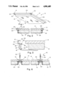
- FIG. 1 is an isometric view of an acoustical panel made in accordance with the present invention.
- FIG. 2 is an end sectional view of the panel of FIG. 1 taken on line 2--2 thereof.
- FIG. 3 is an enlarged view of the edge portion of the elements of FIG. 2 prior to their being assembled together, to illustrate the manner of their being assembled.
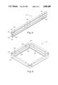
- FIG. 4 is an isometric view of the elongate formed sheet metal frame element prior to final bending, showing shear lines and bend lines.
- FIG. 5 is an isometric view of the formed sheet metal frame element of FIG. 4 after bending but prior to being combined with the backer board, the sound absorbing mat and the fabric.
- FIG. 6 is a sectional view of a ceiling consisting of a plurality of acoustical panels mounted on a suspended ceiling grid system.
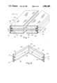
- FIG. 7 is an isometric sectional end view of a modified form of the acoustical panel of the invention, with the backer board centered between two fabric enclosed sound absorbing mats.
- FIG. 8 is an isometric sectional view of a corner portion of the frame of the panel of FIG. 7.
- Panel 10 consists of a light gauge sheet metal frame 12, a gypsum backer board 14, a low density fiber glass mat 16 and a porous fabric facing 18.
- the gypsum backer board 14 will be seen to have exposed portions 20 at each corner of the panel 10.
- the gypsum backer board 14 has the four side edges 22 each inserted into an inwardly opening channel 24 in each of the four sides 25 of frame 12.
- the frame 12 will be seen to have locking barbs 26 in channels 24 which prevent the frame 12 from coming off of the edges 22 of the gypsum backer board 14.
- the gypsum backer board 14 is a paper covered, gypsum-core board of about 3/8 inch to 5/8 inch thickness.
- the metal frame is shown in FIG. 4 and 5 to be originally an elongate roll-formed sheet metal element 27 having, along the top, the channel 24, an outwardly opening fabric retainer rebend 28 formed immediately below channel 24, and a downwardly extending flange 30 below the rebend 28, inward of the outer bottom 29 of channel 24.
- An upwardly turned hem 32 is formed along the bottom of flange 30.
- Element 27 is shown to have shear lines 34 at three spaced parallel positions whereat the channel portion 24 is totally severed, and indented bend lines 36 extending from the shear lines 34 across the rebend 28, the flange 30 and the hem 32.
- Assembly of the panel will be seen to consist of the steps of folding the element 27 into the four-sided frame 12, along bend lines 36.
- the gypsum backer board edges 22 Prior to completion of this bending step, the gypsum backer board edges 22 are pushed into the channels 24.
- Fiber glass mat 16 is then placed within the confines of the four flanges 30, and the fabric facing 18 is affixed over the surface of the mat 16 and around the outside of flanges 30.
- the four edges 38 of fabric facing 18 are inserted into the four rebends 28 of the four sides 25 of frame 12, and the four rebends 28 are crimped to a tightly rebent rebend 28, by pushing flanges 30 upward against the bottom side 40 of board 14.
- the fabric facing 18 is caused to be stretched tightly across the face of the mat 16, as the edges 38 are being locked into the rebend 28.
- the fabric facing 18 conceals the mat 16 and the flanges 30 of the four sides 25.
- the frame 12 is made of a light gauge sheet metal, preferably about 0.012 inch, galvanized steel, which is roll-formed to the cross-sectional shape described above for metal element 27.
- the light gauge metal is adequate for producing a structurally rigid, stable acoustical panel due to the combination of the frame 12 with a rigid gypsum backer board 14, with the gypsum backer board edges 22 completely filling the channels 24 of the four sides 25 of frame 12, and being locked into the channels by barbs 26.
- frame 12 could also be made of a low cost plastic extrusion, such as of rigid polyvinyl chloride, with shear lines 34 cut into the channel 24 and bend lines 36 formed in rebend 28, flange 30 and hem 32. A temporary heating of the polyvinyl chloride rebends 28 is necessary during attachment of the fabric edges 38 within the rebends 28.
- the four sides 25 are of equal length, forming a square panel 10 of about one to four feet on each side. It is contemplated that rectangular panels of, for example, two feet by four feet, can also be formed in accordance with the invention.
- the gypsum backer board 14 can be replaced by any other equivalent rigid board, such as a fiber cement board, or a wood fiber board.
- the fiber glass mat 16 can be replaced by any other equivalent low density sound absorbing material.
- T-runners 44 have an inverted-T cross section with a vertical web 46 and at the bottom thereof a pair of oppositely directed horizontal flanges 48.
- the channels 24 of frames 12 rest on top of the flanges 48.
- T-runners 44 are suspended from a building ceiling or ceiling framework (not shown) by wires 50 affixed to webs 46.
- the portion of panels 10 which is covered by fabric facing 18 is all that is visible of panel 10, from below, presenting an appearance of a downwardly protruding, box-like, spaced-apart plurality of ceiling panels.
- the channels 24 and the rigid board 14 therein, will be seen to have a greater area than the area of the confines of the flanges 30, forming a shoulder 52 which rests on the flanges 48.
- FIG. 7 A modification of the invention is shown in FIG. 7, wherein a two-sided acoustical panel 60 consists of a light gauge sheet metal frame 62, a gypsum center board 64, two low density fiber glass mats 66, 66 and two porous fabric facings 68, 68.
- the gypsum center board 64 has four side edges 70 each inserted into an inwardly opening channel 72 in each of the four sides 74 of frame 62.
- the frame 62 will be seen to have locking barbs 76 in channels 72 which prevent the frame 62 from coming off the edges 70 of the gypsum center board 64.
- the metal frame 62 is an elongate roll-formed sheet metal element having a central inwardly opening channel 72 with an outwardly opening fabric retainer rebend 78 formed along each side of channel 72. Extending upwardly and downwardly from respectively the upper and the lower rebends 78 are flanges 80. A reverse hem 82 is formed along the outer edge of each flange 80.
- Panel 60 is assembled in substantially the same way as panel 10, with the gypsum board edges 70 inserted and affixed into channels 72.
- the two fiber glass mats 66, 66 are placed within the confines of the two opposed flanges 80, 80 and the two fabric facings 68, 68 are affixed over the surfaces of the mats 66, 66 and around the outside of flanges 80, 80.
- the four edges 88 of each fabric facing 68, 68 are inserted into the respective rebends 78, 78 of the four sides 74 of frame 62, and the eight rebends 78 of the four sides 74 are crimped to a tightly rebent rebend 78, by pushing the opposed flanges 80, 80 together.
- the two-sided panel 60 is constructed to provide a vertically disposed area separator with sound absorption provided relative to sound produced on both sides of the panel 60.
- the gypsum backer board 14 of panel 10 and the gypsum center board 64 of panel 60 are both able to provide their respective panels with good sound transmission loss characteristics.
Abstract
Description
Claims (16)
Priority Applications (2)
| Application Number | Priority Date | Filing Date | Title |
|---|---|---|---|
| US07/334,039 US4901485A (en) | 1989-04-06 | 1989-04-06 | Acoustical panel |
| CA000600739A CA1308668C (en) | 1989-04-06 | 1989-05-25 | Acoustical panel |
Applications Claiming Priority (1)
| Application Number | Priority Date | Filing Date | Title |
|---|---|---|---|
| US07/334,039 US4901485A (en) | 1989-04-06 | 1989-04-06 | Acoustical panel |
Publications (1)
| Publication Number | Publication Date |
|---|---|
| US4901485A true US4901485A (en) | 1990-02-20 |
Family
ID=23305314
Family Applications (1)
| Application Number | Title | Priority Date | Filing Date |
|---|---|---|---|
| US07/334,039 Expired - Lifetime US4901485A (en) | 1989-04-06 | 1989-04-06 | Acoustical panel |
Country Status (2)
| Country | Link |
|---|---|
| US (1) | US4901485A (en) |
| CA (1) | CA1308668C (en) |
Cited By (44)
| Publication number | Priority date | Publication date | Assignee | Title |
|---|---|---|---|---|
| US5226720A (en) * | 1992-01-08 | 1993-07-13 | Ecolite Manufacturing Company, Inc. | Louver adapter for "T" rail mounted light fixtures |
| FR2727711A1 (en) * | 1994-12-05 | 1996-06-07 | Newmat Sa | Suspended ceiling slab structure with facing sheet |
| FR2751682A1 (en) * | 1996-07-26 | 1998-01-30 | Fernand Scherrer | WALL FABRIC TILE |
| US5974754A (en) * | 1994-08-29 | 1999-11-02 | Armstrong World Industries, Inc. | Ceiling board corner embossing |
| US6244378B1 (en) * | 1998-12-11 | 2001-06-12 | Owens Corning Fiberglas Technology, Inc. | Dual sonic character acoustic panel and systems for use thereof |
| WO2001094715A1 (en) * | 2000-06-07 | 2001-12-13 | Eduardo Huarte Erro | Improved array for covering and ornamenting ceilings |
| EP1167648A2 (en) * | 2000-06-20 | 2002-01-02 | Sadi S.P.A. | Suspension system for false ceiling panels |
| US6387172B1 (en) | 2000-04-25 | 2002-05-14 | United States Gypsum Company | Gypsum compositions and related methods |
| EP1260645A2 (en) * | 2001-05-15 | 2002-11-27 | M. Goffard Louis | Ceilng slab |
| US20040172907A1 (en) * | 2003-03-03 | 2004-09-09 | Eric Krantz-Lilienthal | Suspension system and structure for securing border ceiling panels |
| US6789645B1 (en) | 1999-06-09 | 2004-09-14 | The Dow Chemical Company | Sound-insulating sandwich element |
| US20050055935A1 (en) * | 2003-08-19 | 2005-03-17 | Layfield Derek J. | Interior wall and partition construction |
| FR2875520A1 (en) * | 2004-09-20 | 2006-03-24 | Structures Fixations Panneaux | Modular panel for surface covering e.g. ceiling, has frame including profile that has longitudinal parts with U-shaped and L-shaped transversal sections, where side of one section is contiguous to upper part of side of another section |
| US20060179765A1 (en) * | 2005-01-31 | 2006-08-17 | Howard Meghan L | Adaptable ceiling tile system |
| US20070079562A1 (en) * | 2003-12-30 | 2007-04-12 | Buck Frederick A | Ceiling tile assembly |
| WO2007051927A1 (en) * | 2005-11-03 | 2007-05-10 | Newmat Sa | Profile for a frame to be pocketed |
| US20070125010A1 (en) * | 2004-10-21 | 2007-06-07 | Panagiotis Papakonstantinou | Sound absorbing panel |
| US20080066394A1 (en) * | 2004-01-28 | 2008-03-20 | Art Andersen A/S | Panels and Systems of Such Panels for Instance for Suspended Ceilings |
| US20080086962A1 (en) * | 2006-10-16 | 2008-04-17 | Jahn Peter G | Concealed ceiling panel system |
| US20080148665A1 (en) * | 2006-12-21 | 2008-06-26 | Yonash Richard F | Ceiling tiles made of rigid pvc |
| US20080196337A1 (en) * | 2007-02-15 | 2008-08-21 | Surowiecki Matt F | Slotted track with double-ply sidewalls |
| NL1034759C2 (en) * | 2007-11-26 | 2009-05-27 | Benjamin Martinus Schoonewagen | Suspended ceiling system for use in e.g. office, has carrier rails with support legs and under surfaces, and film-shaped image carriers adapted to be affixed on under surfaces of carrier rails |
| US7546707B1 (en) | 2006-08-29 | 2009-06-16 | California Portable Dance Floor Company, Inc. | Portable floor |
| US20090188195A1 (en) * | 2007-03-07 | 2009-07-30 | Mcgee Wayne | Panelized Ceiling System |
| US20100077695A1 (en) * | 2006-09-08 | 2010-04-01 | Airbus France | Panel assembly and manufacturing method |
| US7798287B1 (en) * | 2005-01-20 | 2010-09-21 | Serious Materials, Inc. | Acoustical ceiling panels |
| US20120137611A1 (en) * | 2009-02-11 | 2012-06-07 | Sportsfield Specialties | Outdoor wall padding apparatus and method for forming the same |
| USD674123S1 (en) | 2011-10-25 | 2013-01-08 | Empire West, Inc. | Ceiling tile |
| US20130239493A1 (en) * | 2012-03-14 | 2013-09-19 | Next Industries, LLC | Suspended ceiling panel system for residential and commercial buildings |
| FR2998603A1 (en) * | 2012-11-27 | 2014-05-30 | Decibel France | Device i.e. panel, for use at e.g. ceiling to absorb acoustic waves in e.g. conference hall, has textile coating supported by peripheral modular frame that includes groove maintaining removable central core i.e. perforated sheet |
| US20150096832A1 (en) * | 2013-10-09 | 2015-04-09 | Stillpoints LLC | Acoustic Panel |
| US20150267416A1 (en) * | 2011-10-11 | 2015-09-24 | Pierre Breese | Device for Re-Cladding a Removeable False-Wall Panel |
| US9238933B1 (en) * | 2013-05-09 | 2016-01-19 | Daniel Avissato | Framing elements |
| US20160168851A1 (en) * | 2014-09-29 | 2016-06-16 | Armstrong World Industries, Inc. | Ceiling system |
| US9534383B1 (en) * | 2015-10-22 | 2017-01-03 | Usg Interiors, Llc | Ceiling panel system |
| USD788943S1 (en) | 2016-03-08 | 2017-06-06 | Daniel A. Avissato | Framing element |
| US9745748B2 (en) * | 2015-11-09 | 2017-08-29 | Awi Licensing Llc | Ceiling system |
| US9850657B2 (en) * | 2016-02-25 | 2017-12-26 | Steelcase Inc. | Acoustic panel for partition wall assembly |
| US10196826B1 (en) | 2018-04-16 | 2019-02-05 | EverBlock Systems, LLC | Elevated flooring system |
| US20190078325A1 (en) * | 2017-09-13 | 2019-03-14 | Semco Llc | Layered fire-retardant panel |
| JP2020071412A (en) * | 2018-11-01 | 2020-05-07 | 株式会社内田洋行 | Sound absorbing panel |
| USD895161S1 (en) | 2019-04-12 | 2020-09-01 | Signature Systems Group Llc | Modular flooring tile |
| US11459753B2 (en) * | 2020-08-31 | 2022-10-04 | Porta-Fab Corporation | Modular ceiling system |
| US11821205B2 (en) | 2020-08-31 | 2023-11-21 | Porta-Fab Corporation | Modular ceiling system |
Citations (8)
| Publication number | Priority date | Publication date | Assignee | Title |
|---|---|---|---|---|
| US2192653A (en) * | 1937-11-13 | 1940-03-05 | Schenk Eduard | Acoustic construction |
| US3706171A (en) * | 1971-04-02 | 1972-12-19 | Harry I Shayman | Decorative acoustical ceiling panel |
| US3712846A (en) * | 1971-06-23 | 1973-01-23 | Carpenter L & Co | Acoustical panel |
| US4194329A (en) * | 1976-01-20 | 1980-03-25 | Wendt Alan C | Sound absorbing panels |
| US4283891A (en) * | 1979-07-05 | 1981-08-18 | Moeller Wolfgang W | Ceiling tile system |
| US4291783A (en) * | 1978-12-26 | 1981-09-29 | Owens-Corning Fiberglas Corporation | Acoustical panel for suspended ceilings |
| US4423573A (en) * | 1978-11-08 | 1984-01-03 | American Seating Company | Wall panel with removable acoustical insert |
| US4428454A (en) * | 1981-09-24 | 1984-01-31 | Capaul Raymond W | Acoustical panel construction |
-
1989
- 1989-04-06 US US07/334,039 patent/US4901485A/en not_active Expired - Lifetime
- 1989-05-25 CA CA000600739A patent/CA1308668C/en not_active Expired - Lifetime
Patent Citations (8)
| Publication number | Priority date | Publication date | Assignee | Title |
|---|---|---|---|---|
| US2192653A (en) * | 1937-11-13 | 1940-03-05 | Schenk Eduard | Acoustic construction |
| US3706171A (en) * | 1971-04-02 | 1972-12-19 | Harry I Shayman | Decorative acoustical ceiling panel |
| US3712846A (en) * | 1971-06-23 | 1973-01-23 | Carpenter L & Co | Acoustical panel |
| US4194329A (en) * | 1976-01-20 | 1980-03-25 | Wendt Alan C | Sound absorbing panels |
| US4423573A (en) * | 1978-11-08 | 1984-01-03 | American Seating Company | Wall panel with removable acoustical insert |
| US4291783A (en) * | 1978-12-26 | 1981-09-29 | Owens-Corning Fiberglas Corporation | Acoustical panel for suspended ceilings |
| US4283891A (en) * | 1979-07-05 | 1981-08-18 | Moeller Wolfgang W | Ceiling tile system |
| US4428454A (en) * | 1981-09-24 | 1984-01-31 | Capaul Raymond W | Acoustical panel construction |
Cited By (69)
| Publication number | Priority date | Publication date | Assignee | Title |
|---|---|---|---|---|
| US5226720A (en) * | 1992-01-08 | 1993-07-13 | Ecolite Manufacturing Company, Inc. | Louver adapter for "T" rail mounted light fixtures |
| US5974754A (en) * | 1994-08-29 | 1999-11-02 | Armstrong World Industries, Inc. | Ceiling board corner embossing |
| FR2727711A1 (en) * | 1994-12-05 | 1996-06-07 | Newmat Sa | Suspended ceiling slab structure with facing sheet |
| FR2751682A1 (en) * | 1996-07-26 | 1998-01-30 | Fernand Scherrer | WALL FABRIC TILE |
| WO1998004791A1 (en) * | 1996-07-26 | 1998-02-05 | Scherrer, Jean-Marc | Stretched-fabric wall slab |
| US6244378B1 (en) * | 1998-12-11 | 2001-06-12 | Owens Corning Fiberglas Technology, Inc. | Dual sonic character acoustic panel and systems for use thereof |
| US6789645B1 (en) | 1999-06-09 | 2004-09-14 | The Dow Chemical Company | Sound-insulating sandwich element |
| US6387172B1 (en) | 2000-04-25 | 2002-05-14 | United States Gypsum Company | Gypsum compositions and related methods |
| US6481171B2 (en) | 2000-04-25 | 2002-11-19 | United States Gypsum Company | Gypsum compositions and related methods |
| WO2001094715A1 (en) * | 2000-06-07 | 2001-12-13 | Eduardo Huarte Erro | Improved array for covering and ornamenting ceilings |
| EP1167648A3 (en) * | 2000-06-20 | 2002-05-15 | Sadi S.P.A. | Suspension system for false ceiling panels |
| US6513295B2 (en) | 2000-06-20 | 2003-02-04 | Sadi S.P.A. | Suspension system for false ceiling panels |
| EP1167648A2 (en) * | 2000-06-20 | 2002-01-02 | Sadi S.P.A. | Suspension system for false ceiling panels |
| EP1260645A2 (en) * | 2001-05-15 | 2002-11-27 | M. Goffard Louis | Ceilng slab |
| EP1260645A3 (en) * | 2001-05-15 | 2003-08-06 | M. Goffard Louis | Ceilng slab |
| US7143562B2 (en) * | 2003-03-03 | 2006-12-05 | Awi Licensing Company | Suspension system and structure for securing border ceiling panels |
| US20040172907A1 (en) * | 2003-03-03 | 2004-09-09 | Eric Krantz-Lilienthal | Suspension system and structure for securing border ceiling panels |
| US20050055935A1 (en) * | 2003-08-19 | 2005-03-17 | Layfield Derek J. | Interior wall and partition construction |
| US7032356B2 (en) | 2003-08-19 | 2006-04-25 | Layfield Derek J | Interior wall and partition construction |
| US20070079562A1 (en) * | 2003-12-30 | 2007-04-12 | Buck Frederick A | Ceiling tile assembly |
| US7954293B2 (en) * | 2004-01-28 | 2011-06-07 | Soft Cells A/S | Panels and systems of such panels for instance for suspended ceilings |
| US20080066394A1 (en) * | 2004-01-28 | 2008-03-20 | Art Andersen A/S | Panels and Systems of Such Panels for Instance for Suspended Ceilings |
| FR2875520A1 (en) * | 2004-09-20 | 2006-03-24 | Structures Fixations Panneaux | Modular panel for surface covering e.g. ceiling, has frame including profile that has longitudinal parts with U-shaped and L-shaped transversal sections, where side of one section is contiguous to upper part of side of another section |
| US20070125010A1 (en) * | 2004-10-21 | 2007-06-07 | Panagiotis Papakonstantinou | Sound absorbing panel |
| US7412801B2 (en) | 2004-10-21 | 2008-08-19 | Panagiotis Papakonstantinou | Sound absorbing panel |
| US7798287B1 (en) * | 2005-01-20 | 2010-09-21 | Serious Materials, Inc. | Acoustical ceiling panels |
| US20060179765A1 (en) * | 2005-01-31 | 2006-08-17 | Howard Meghan L | Adaptable ceiling tile system |
| WO2007051927A1 (en) * | 2005-11-03 | 2007-05-10 | Newmat Sa | Profile for a frame to be pocketed |
| US20070157535A1 (en) * | 2005-11-03 | 2007-07-12 | Etienne Cousin | Fabric support frame section |
| CN101316974B (en) * | 2005-11-03 | 2012-12-05 | 纽曼特股份公司 | Frame for insertion |
| US7685786B2 (en) * | 2005-11-03 | 2010-03-30 | Etienne Cousin | Fabric support frame section |
| US7546707B1 (en) | 2006-08-29 | 2009-06-16 | California Portable Dance Floor Company, Inc. | Portable floor |
| US20100077695A1 (en) * | 2006-09-08 | 2010-04-01 | Airbus France | Panel assembly and manufacturing method |
| US8544176B2 (en) * | 2006-09-08 | 2013-10-01 | Airbus Operations Sas | Method of forming a panel assembly of a ventral fairing of an aircraft |
| US7841149B2 (en) * | 2006-10-16 | 2010-11-30 | Chicago Metallic Corporation | Concealed ceiling panel system |
| US20110067337A1 (en) * | 2006-10-16 | 2011-03-24 | Jahn Peter G | Concealed Ceiling Panel System |
| US20080086962A1 (en) * | 2006-10-16 | 2008-04-17 | Jahn Peter G | Concealed ceiling panel system |
| US20080148665A1 (en) * | 2006-12-21 | 2008-06-26 | Yonash Richard F | Ceiling tiles made of rigid pvc |
| US7735295B2 (en) * | 2007-02-15 | 2010-06-15 | Surowiecki Matt F | Slotted track with double-ply sidewalls |
| US20080196337A1 (en) * | 2007-02-15 | 2008-08-21 | Surowiecki Matt F | Slotted track with double-ply sidewalls |
| US20090188195A1 (en) * | 2007-03-07 | 2009-07-30 | Mcgee Wayne | Panelized Ceiling System |
| NL1034759C2 (en) * | 2007-11-26 | 2009-05-27 | Benjamin Martinus Schoonewagen | Suspended ceiling system for use in e.g. office, has carrier rails with support legs and under surfaces, and film-shaped image carriers adapted to be affixed on under surfaces of carrier rails |
| US8424249B2 (en) * | 2009-02-11 | 2013-04-23 | Sportsfield Specialties, Inc. | Outdoor wall padding apparatus and method for forming the same |
| US20120137611A1 (en) * | 2009-02-11 | 2012-06-07 | Sportsfield Specialties | Outdoor wall padding apparatus and method for forming the same |
| US20150267416A1 (en) * | 2011-10-11 | 2015-09-24 | Pierre Breese | Device for Re-Cladding a Removeable False-Wall Panel |
| US10273696B2 (en) * | 2011-10-11 | 2019-04-30 | Jean-Marc Scherrer | Device for re-cladding a removeable false-wall panel |
| USD684707S1 (en) | 2011-10-25 | 2013-06-18 | Empire West, Inc. | Ceiling tile |
| USD674123S1 (en) | 2011-10-25 | 2013-01-08 | Empire West, Inc. | Ceiling tile |
| US20130239493A1 (en) * | 2012-03-14 | 2013-09-19 | Next Industries, LLC | Suspended ceiling panel system for residential and commercial buildings |
| FR2998603A1 (en) * | 2012-11-27 | 2014-05-30 | Decibel France | Device i.e. panel, for use at e.g. ceiling to absorb acoustic waves in e.g. conference hall, has textile coating supported by peripheral modular frame that includes groove maintaining removable central core i.e. perforated sheet |
| US9238933B1 (en) * | 2013-05-09 | 2016-01-19 | Daniel Avissato | Framing elements |
| US9702143B2 (en) * | 2013-10-09 | 2017-07-11 | Stillpoints LLC | Acoustic panel |
| US20150096832A1 (en) * | 2013-10-09 | 2015-04-09 | Stillpoints LLC | Acoustic Panel |
| US10151105B2 (en) * | 2013-10-09 | 2018-12-11 | Stillpoints LLC | Acoustic panel |
| US20170306617A1 (en) * | 2013-10-09 | 2017-10-26 | Stillpoints LLC | Acoustic Panel |
| US20160168851A1 (en) * | 2014-09-29 | 2016-06-16 | Armstrong World Industries, Inc. | Ceiling system |
| US9637919B2 (en) * | 2014-09-29 | 2017-05-02 | Awi Licensing Llc | Ceiling system |
| US9534383B1 (en) * | 2015-10-22 | 2017-01-03 | Usg Interiors, Llc | Ceiling panel system |
| US9745748B2 (en) * | 2015-11-09 | 2017-08-29 | Awi Licensing Llc | Ceiling system |
| US9850657B2 (en) * | 2016-02-25 | 2017-12-26 | Steelcase Inc. | Acoustic panel for partition wall assembly |
| USD788943S1 (en) | 2016-03-08 | 2017-06-06 | Daniel A. Avissato | Framing element |
| US20190078325A1 (en) * | 2017-09-13 | 2019-03-14 | Semco Llc | Layered fire-retardant panel |
| US10837170B2 (en) | 2017-09-13 | 2020-11-17 | Semco Llc | Fire-retardant panel with frame |
| US11339567B2 (en) | 2017-09-13 | 2022-05-24 | Semco Llc | Fire-retardant panel with frame |
| US10196826B1 (en) | 2018-04-16 | 2019-02-05 | EverBlock Systems, LLC | Elevated flooring system |
| JP2020071412A (en) * | 2018-11-01 | 2020-05-07 | 株式会社内田洋行 | Sound absorbing panel |
| USD895161S1 (en) | 2019-04-12 | 2020-09-01 | Signature Systems Group Llc | Modular flooring tile |
| US11459753B2 (en) * | 2020-08-31 | 2022-10-04 | Porta-Fab Corporation | Modular ceiling system |
| US11821205B2 (en) | 2020-08-31 | 2023-11-21 | Porta-Fab Corporation | Modular ceiling system |
Also Published As
| Publication number | Publication date |
|---|---|
| CA1308668C (en) | 1992-10-13 |
Similar Documents
| Publication | Publication Date | Title |
|---|---|---|
| US4901485A (en) | Acoustical panel | |
| US5715638A (en) | Fabric wall panel system | |
| US4719730A (en) | Acoustical tack board | |
| US3748799A (en) | Sound-absorbent panel | |
| US3153304A (en) | Acoustical suspended ceiling | |
| US5724780A (en) | Metal building roof structure | |
| US3579937A (en) | Foam plastic panel without truss members | |
| EP1904695B1 (en) | Suspension systems | |
| US4433514A (en) | Ceiling system for small buildings | |
| US4016689A (en) | Sound absorbing panel system and method for connecting panels | |
| US4611444A (en) | Sanitary acoustical ceiling | |
| US4479339A (en) | Cover member for and method of installing insulation boards | |
| US6513295B2 (en) | Suspension system for false ceiling panels | |
| EP0149641A1 (en) | System for supporting and retaining insulation | |
| US3994104A (en) | Supported roof structure | |
| US2704865A (en) | Acoustical treatment | |
| CA1308227C (en) | Sag resistant ceiling panel | |
| EP2362031B1 (en) | Section for use in a system wall system; wall using such a section and tape system to be used on such a section | |
| GB2239464A (en) | Panel/portable room | |
| US6003272A (en) | Insulated eave strut member | |
| US2147667A (en) | Prefabricated building | |
| JP2517194B2 (en) | Assembly method for boundary wall of unit building | |
| US3504462A (en) | Lay-in type suspended ceiling and panel therefor | |
| JP2002004540A (en) | Method for fixing thermal insulating material to interior finishing substrate panel and interior finishing substrate material | |
| JPH0972013A (en) | Heat insulating material for wooden building |
Legal Events
| Date | Code | Title | Description |
|---|---|---|---|
| AS | Assignment |
Owner name: NATIONAL GYPSUM COMPANY, A DE CORP., TEXAS Free format text: ASSIGNMENT OF ASSIGNORS INTEREST.;ASSIGNORS:MENCHETTI, ROBERT J.;HEUER, ANDREW E.;REEL/FRAME:005071/0211 Effective date: 19890403 |
|
| STCF | Information on status: patent grant |
Free format text: PATENTED CASE |
|
| AS | Assignment |
Owner name: GENERAL ELECTRIC CAPITAL CORPORATION, A CORP. OF N Free format text: SECURITY INTEREST;ASSIGNOR:NATIONAL GYPSUM COMPANY;REEL/FRAME:005548/0167 Effective date: 19901029 |
|
| FPAY | Fee payment |
Year of fee payment: 4 |
|
| AS | Assignment |
Owner name: NATIONAL GYPSUM COMPANY, NORTH CAROLINA Free format text: PARTY RELEASING LIENS;;ASSIGNOR:GENERAL ELECTRIC CAPITAL CORPORATION, A NEW YORK CORPORATION;REEL/FRAME:006768/0726 Effective date: 19930709 Owner name: NATIONAL GYPSUM COMPANY, NORTH CAROLINA Free format text: ASSIGNMENT OF ASSIGNORS INTEREST;ASSIGNOR:NATIONAL GYPSUM COMPANY, A DELAWARE CORPORATION, NOW NAMED ABESTOS CLAIMS MANAGEMENT CORPORATION;REEL/FRAME:006768/0694 Effective date: 19930701 Owner name: GENERAL ELECTRIC CAPITAL CORPORATION, CALIFORNIA Free format text: LICENSE;ASSIGNOR:NATIONAL GYPSUM COMPANY A CORP. OF DELAWARE;REEL/FRAME:006723/0785 Effective date: 19930630 |
|
| AS | Assignment |
Owner name: NATIONAL GYPSUM COMPANY Free format text: ASSIGNMENT AND RELEASE, SATISFACTION AND DISCHARGE OF MORTGAGE OF PATENTS AND PATENT LICENSES;ASSIGNOR:GENERAL ELECTRIC CAPITAL CORPORATION;REEL/FRAME:007153/0387 Effective date: 19940912 |
|
| AS | Assignment |
Owner name: NATIONSBANK, N.A. (CAROLINAS), NORTH CAROLINA Free format text: SECURITY AGREEMENT;ASSIGNOR:NATIONAL GYPSUM COMPANY, A DE CORP.;REEL/FRAME:007661/0624 Effective date: 19950920 |
|
| FEPP | Fee payment procedure |
Free format text: PAYOR NUMBER ASSIGNED (ORIGINAL EVENT CODE: ASPN); ENTITY STATUS OF PATENT OWNER: LARGE ENTITY |
|
| FPAY | Fee payment |
Year of fee payment: 8 |
|
| AS | Assignment |
Owner name: NATIONAL GYPSUM PROPERTIES LLC, NORTH CAROLINA Free format text: ASSIGNMENT OF ASSIGNORS INTEREST;ASSIGNOR:NATIONAL GYPSUM COMPANY, A DELAWARE CORPORATION;REEL/FRAME:010539/0326 Effective date: 19991230 |
|
| AS | Assignment |
Owner name: NATIONAL GYPSUM PROPERTIES, LLC, A CORPORATION OF Free format text: RELEASE OF SECURITY INTEREST;ASSIGNOR:BANK OF AMERICA, N.A., AS ADMINISTRATIVE AGENT, FORMERLY NATIONSBANK, N.A. (CAROLINAS), A NATIONAL BANK;REEL/FRAME:010676/0273 Effective date: 19991109 |
|
| AS | Assignment |
Owner name: BANK OF AMERICA, N.A., NORTH CAROLINA Free format text: SECURITY AGREEMENT;ASSIGNOR:NATIONAL GYPSUM PROPERTIES, LLC;REEL/FRAME:011770/0536 Effective date: 20010423 |
|
| FPAY | Fee payment |
Year of fee payment: 12 |
|
| AS | Assignment |
Owner name: NATIONAL GYPSUM PROPERTIES, LLC, NORTH CAROLINA Free format text: RELEASE BY SECURED PARTY;ASSIGNOR:BANK OF AMERICA, N.A.;REEL/FRAME:018260/0145 Effective date: 20060905 Owner name: NEW NGC, INC., D/B/A NATIONAL GYPSUM COMPANY, NORT Free format text: RELEASE BY SECURED PARTY;ASSIGNOR:BANK OF AMERICA, N.A.;REEL/FRAME:018260/0145 Effective date: 20060905 |
|
| AS | Assignment |
Owner name: BANK OF AMERICA, N.A., NORTH CAROLINA Free format text: SECURITY AGREEMENT;ASSIGNOR:NATIONAL GYPSUM PROPERTIES, LLC;REEL/FRAME:020741/0807 Effective date: 20080324 |