US4901490A - Raised flooring panel and raised flooring assemblies - Google Patents
Raised flooring panel and raised flooring assemblies Download PDFInfo
- Publication number
- US4901490A US4901490A US06/682,608 US68260884A US4901490A US 4901490 A US4901490 A US 4901490A US 68260884 A US68260884 A US 68260884A US 4901490 A US4901490 A US 4901490A
- Authority
- US
- United States
- Prior art keywords
- flooring
- panel
- raised
- unitary
- supported
- Prior art date
- Legal status (The legal status is an assumption and is not a legal conclusion. Google has not performed a legal analysis and makes no representation as to the accuracy of the status listed.)
- Expired - Fee Related
Links
Images
Classifications
-
- E—FIXED CONSTRUCTIONS
- E04—BUILDING
- E04F—FINISHING WORK ON BUILDINGS, e.g. STAIRS, FLOORS
- E04F15/00—Flooring
- E04F15/02—Flooring or floor layers composed of a number of similar elements
- E04F15/024—Sectional false floors, e.g. computer floors
- E04F15/02447—Supporting structures
- E04F15/02452—Details of junctions between the supporting structures and the panels or a panel-supporting framework
-
- E—FIXED CONSTRUCTIONS
- E04—BUILDING
- E04F—FINISHING WORK ON BUILDINGS, e.g. STAIRS, FLOORS
- E04F15/00—Flooring
- E04F15/02—Flooring or floor layers composed of a number of similar elements
- E04F15/024—Sectional false floors, e.g. computer floors
- E04F15/02405—Floor panels
-
- E—FIXED CONSTRUCTIONS
- E04—BUILDING
- E04F—FINISHING WORK ON BUILDINGS, e.g. STAIRS, FLOORS
- E04F15/00—Flooring
- E04F15/02—Flooring or floor layers composed of a number of similar elements
- E04F15/024—Sectional false floors, e.g. computer floors
- E04F15/02447—Supporting structures
- E04F15/02458—Framework supporting the panels
Definitions
- the present invention relates in general to raised flooring panels and raised flooring assemblies, and more particularly to a raised flooring panel and a raised flooring assembly with improved structural characteristics.
- Raised flooring has heretofore been employed in the construction of buildings.
- Liskey, Inc. has sold raised flooring panels with radial rib design and raised flooring assemblies with stringers forming a grid.
- Innocrete Systems, Inc. has sold access flooring or elevated flooring panels and elevated flooring assemblies.
- the panels were made of a silicate compound.
- an elevated floor comprised of stringers and floor panels.
- the floor covering above the floor panel is composed of rubber or plastic tile.
- the floor panel is fabricated or extruded aluminum.
- the floor panel has a rubber or plastic tile thereabove as a floor covering and is composed of the extruded aluminum sections.
- a floor panel from at least two veneer boards with an intermediate layer of a rubber-like elastic material, such as butadiene acrylonitrile rubber, polyisobutylene rubber, ethylene-propylene rubber, or may be formed of a rubber composition formed of rubber-like elastic material blended with polyvinyl chloride, polybutene or inorganic filler.
- a rubber-like elastic material such as butadiene acrylonitrile rubber, polyisobutylene rubber, ethylene-propylene rubber, or may be formed of a rubber composition formed of rubber-like elastic material blended with polyvinyl chloride, polybutene or inorganic filler.
- An object of the present invention is to provide an improved raised flooring panel which is electrically insulating.
- Another object of the present invention is to provide an improved raised flooring panel which is relatively light.
- Another object of the present invention is to provide an improved raised flooring panel which is relatively inexpensive to manufacture and install.
- Another object of the present invention is to provide an improved raised flooring panel which is more easily adapted to the shape of mating structures during its installation.
- Another object of the present invention is to provide an improved raised flooring panel which is relatively simple to manufacture.
- the present invention is a unitary, injection-molded raised flooring panel adapted to be received onto a grid of flooring panel support stringers.
- the unitary, injection-molded raised flooring panel includes a continuous flooring wall, the upper surface of which is the flooring surface of panels. Formed integrally with and depending beneath the continuous flooring wall of the flooring panels are a plurality of mutually intersecting reinforcing ribs. In its preferred embodiment, the intersecting reinforcing ribs at the center of the flooring panels seat on a panel support pedestal.
- the flooring panel is formed from a thermoplastic, or a thermosetting plastic, or a synthetic, polymeric resin material which is fabricated into the panel in a single manufacturing operation.
- the unitary, injection-molded raised flooring panel of the present invention requires no additional covering on its flooring surface, such as flooring tiles or carpeting.
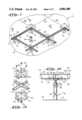
- FIG. 1 is a diagrammatic perspective view illustrating a fragmentary raised flooring assembly embodying the present invention with a flooring panel removed to illustrate a grid of flooring panel support stringers supported upon grid support pedestals, and a panel support pedestal.
- FIG. 2 is a fragmentary, diagrammatic elevational view of flooring panel support stringers assembled onto a grid support pedestal of a unitary, injection-molded raised flooring panel taken along line 2--2 of FIG. 1 with the support stringer shown partially in section.
- FIG. 3 is an exploded, diagrammatic perspective view depicting an assembly of the flooring panel support stringers onto a grid support pedestal embodied in the raised flooring assembly of the present invention.
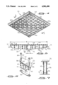
- FIG. 4 is a diagrammatic perspective view of a unitary, injection-molded raised flooring panel embodying the present invention showing its mutually intersecting reinforcing ribs which depend downward from its flooring wall.
- FIG. 5 is a diagrammatic, vertical sectional view of the unitary, injection-molded raised flooring panel taken along line 5--5 of FIG. 4.
- FIG. 6 is a diagrammatic, exploded vertical sectional view illustrating a flooring panel stringer clamp arranged for securing each of its terminal ends to one of a pair of unitary, injectionmolded raised flooring panels.
- FIG. 7 is a diagrammatic elevation view, partially in section, of a panel support pedestal employed in the present invention.
- the raised flooring assembly 10 includes a grid 12 assembled from a plurality of metallic, inverted, T-shaped flooring panel support stringers 14.
- the panel support stringers 14 are supported on a plurality of grid support pedestals 16 which rest on a subfloor 18.
- Supported by the grid 12 are a plurality of square-shaped unitary, injection-molded raised flooring panels 20.
- Located above the center of each unitary, injection-molded raised flooring panel 20 and also resting on the subfloor 18 is a panel support pedestal 26 which supports the center of the unitary, injection-molded raised flooring panel 20.
- each grid support pedestal 16 includes a metallic, hollow pedestal tube 32 secured to a metallic base plate 34 which rests on the subfloor 18. Received into each hollow pedestal tube 32 is a metallic, threaded pedestal jack 36 onto which a pair of leveling nuts 38 are secured and about which a locking cap 40 is disposed.
- the leveling nuts 38 of each grid support pedestal 16 are adjusted to establish the height of the grid 12 above the subfloor 18 and then the leveling nuts 38 are tightened together.
- the locking cap 40 of each grid support pedestal 16 is lowered over the leveling nuts 38.
- the locking cap 40 prevents spontaneous loosening of the leveling nuts 38 and consequently keeps the height of each of the grid support pedestals 16 in the adjusted position.
- a square-shaped, metallic pedestal head 42 upon which the flooring panel support stringers 14 are supported.
- U-shaped troughs 44 formed into the uppermost surface of the square-shaped pedestal head 42 of each grid support pedestal 16 are four U-shaped troughs 44 in which the inverted, T-shaped flooring panel support stringers 14 are received.
- the troughs 44 extend radially outward from the center of the pedestal head 42 thus forming an X-shape centered about the middle of the pedestal head 42.
- each triangularly-shaped stringer clamping plate 46 having an aperture 48 formed therethrough is placed onto the terminal ends of each pair of immediately adjacent flooring panel support stringers 14.
- a screw fastener 52 is then passed through the aperture 48 and secured into one of four mating threaded apertures 54 formed into the pedestal head 42.
- the pedestal head 42 of each grid support pedestal 16 has the terminals ends of four inverted, T-shaped flooring panel support stringers 14 respectively received into the four U-shaped troughs 44 formed into its upper surface.
- each threaded aperture 54 of the pedestal head 42 has secured thereinto the screw fastener 52 which passes through the aperture 48 respectively formed through each of the four stringer clamping plates 46 places onto the terminal ends of each pair of immediately adjacent flooring panel support stringers 14.
- the unitary, injection-molded raised flooring panel 20 includes a base 62a and a plurality of mutually intersecting reinforcing ribs 62 formed integrally with and depending from a continuous flooring wall 64.
- the base 62a extends along the perimeter of the panel 20.
- the reinforcing ribs 62 project away from an upper flooring surface 68 of the flooring wall 64 (FIG. 5) to form a lower surface for the reinforcing ribs 62.
- the reinforcing ribs 62 depend from the lower surface of the flooring surface 68.
- the center of the unitary, injection-molded raised flooring panel 20 is supported by a square-shaped panel support head 72 of the panel support pedestal 26 shown in FIGS. 5 and 7.
- the square-shaped unitary, injection-molded raised flooring panels 20 are made of thermoplastic material, such as acrylonitrile butadiene polystyrene, polyvinyl chloride, polystyrene, polycarbonate, phenolic resins or ureas, or a synthetic, polymeric resin material.
- thermoplastic material such as acrylonitrile butadiene polystyrene, polyvinyl chloride, polystyrene, polycarbonate, phenolic resins or ureas, or a synthetic, polymeric resin material.
- the flooring wall 64 of the panel 20 has a nominal width "W” of 24 inches and nominal thickness "T f " of 0.380 inches, and the mutually intersecting reinforcing ribs 62 have a nominal center-to-center separation "S” between 2.500 and 2.750 inches, a nominal thickness "T r " at the flooring wall 64 of 0.31 inches, a nominal height "H i " about the panel support aperture 66 of 2.5 inches, and a nominal height "H o " of 1.7 inches at the outer edge of the unitary, injection-molded raised flooring panel 20 immediately adjacent to the flooring panel support stringer 14.
- the unitary, injection-molded raised flooring panel 20 of the present invention requires no additional covering material on its upper flooring surface 68, such as flooring tiles or carpeting, normally heretofore used with raised flooring panels.
- the unitary, injection-molded raised flooring panel 20 of the present invention may be completely fabricated in a single injection molding operation.
- the raised flooring assembly 10 of the present invention employing the unitary, injection-molded raised flooring panel 20 is relatively simple and inexpensive to manufacture and install.
- a flooring panel stringer clamp 82 which passes beneath the flooring panel support stringer 14 to secure a pair of unitary, injection-molded raised flooring panels 20 thereto.
- the flooring panel stringer clamp 82 prevents inadvertently displacing the pair of unitary, injection-molded raised flooring panels 20 from the flooring panel support stringer 14 due to the light weight of the unitary, injection-molded raised flooring panels 20.
- the flooring panel stringer clamp 82 is secured beneath the flooring panel support stringer 14 by respectively fastening each of its terminal ends to one of the pair of unitary, injection-molded raised flooring panels by a threaded fastener 84 passing through an aperture 86 formed through each unitary, injection-molded raised flooring panel 20.
- the panel 20 can be integrally formed from separate sections and joined or bonded together using a suitable adhesive, such as polyvinyl chloride or acrylonitrile butadiene styrene or by ultrasonic sound.
- a suitable adhesive such as polyvinyl chloride or acrylonitrile butadiene styrene or by ultrasonic sound.
- the flooring wall 64 is made of one type of plastic material, such as acrylonitrile butadiene styrene, and the reinforcing ribs 62 are made of another type of plastic material, such as polyvinyl chloride.
- the plastic material above-described for the flooring wall 64 tends to last longer and has chemical resistant characteristics.
- the plastic material above-described for the base 62a and ribs 62 tends to be stronger.
- An advantage to the use of the above-described plastic material for the injection molding of the panels 20 is that the resulting panel 20 may be configured to conform to various patterns or to conform to various shapes. Such panels can be cut or drilled without affecting the structural strength and integrity of the panels.
- the panel support pedestal 26 (FIG. 7) comprises the panel support head 72 with a depending cylindrical collar 90. Seated on the subfloor 18 is a base 91 of the pedestal 26, which is formed with an upstanding collar 92. A tube 93 is received by the collars 90 and 92. At the center of the panel 20, the bottom surface of the reinforcing ribs 62 seat on and are fixed to the support head 72 by a suitable adhesive. A central raised section of the support head 72 is reduced in dimensions and enters the central opening between the reinforcing ribs 62.
- the panel support pedestal 26 is made, in the exemplary embodiment, from polyvinyl chloride.
- a suitable adhesive is applied to the exterior wall ends of the tube 93 and to the interior walls of the collars 90 and 92 before the panel 20 is fixed to the grid 12. As the panel 20 is urged downwardly into place, the tube 93 self adjusts within the collars 90 and 92 to seek out its proper height. When the adhesive sets, the support pedestal 26 becomes rigid.
Abstract
Disclosed is a unitary, injection-molded raised flooring panel adapted for use in a raised flooring assembly. The raised flooring assembly includes a grid of flooring panel support stringers onto which the flooring panel is supported. The unitary, injection-molded raised flooring panel includes a continuous flooring wall the upper surface of which is the flooring surface of a panel and a plurality of depending, mutually intersecting reinforcing ribs formed integrally with the flooring wall of the panel. In the preferred embodiment, the flooring panel is made of a thermoplastic material, a thermosetting plastic material or a synthetic polymeric resin material. Thus, the disclosed flooring panel may be completely fabricated in a single manufacturing operation.
Description
The present invention relates in general to raised flooring panels and raised flooring assemblies, and more particularly to a raised flooring panel and a raised flooring assembly with improved structural characteristics.
Raised flooring has heretofore been employed in the construction of buildings. Liskey, Inc. has sold raised flooring panels with radial rib design and raised flooring assemblies with stringers forming a grid. Innocrete Systems, Inc. has sold access flooring or elevated flooring panels and elevated flooring assemblies. The panels were made of a silicate compound. In the patent to Liskey, Jr., U.S. Pat. No. 3,180,460, issued on Apr. 27, 1965, for Floor Panel For Elevated Flooring, there is disclosed an elevated floor comprised of stringers and floor panels. The floor covering above the floor panel is composed of rubber or plastic tile. The floor panel is fabricated or extruded aluminum. Thus, the floor panel has a rubber or plastic tile thereabove as a floor covering and is composed of the extruded aluminum sections.
The patent to Chevaux, U.S. Pat. No. 3,946,529, issued on Mar. 30, 1976, for Floor For Sports And Particularly For Roller Skating, discloses a floor for roller skating. A deck plate is formed and molded or injected molded plastic tiles are installed on the top of the deck plate. While the patent to Donovan, U.S. Pat. No. 3,279,134, issued on Oct. 18, 1966, for Elevated Floor Construction, discloses panels made of vinyl, asphalt, cork and the like. Reinforcing members project from the bottom of the panels. In the patent to Bettinger, U.S. Pat. No. 3,811,237, issued on May 21, 1974, for Raised Floor Panel And Assembly, the panel comprises a core made of high density particle board, such as compressed wood particles.
In the patent to Tharp, U.S. Pat. No. 4,085,557, issued on Apr. 25, 1978, for Raised Access Floor Systems, there is disclosed a floor panel made of a relatively thick chip board material disposed in a pan. A polyvinyl chloride impact molding is fitted between the chip board material and the inner wall of the pan. The polyvinyl chloride molding frames a sheet of galvanized steel on which a carpet is fitted. The patent to Mori et al., U.S. Pat. No. 4,258,516, issued on Mar. 31, 1981, for Apparatus For Supporting Floor Plates Above Substrate, discloses forming a floor panel from at least two veneer boards with an intermediate layer of a rubber-like elastic material, such as butadiene acrylonitrile rubber, polyisobutylene rubber, ethylene-propylene rubber, or may be formed of a rubber composition formed of rubber-like elastic material blended with polyvinyl chloride, polybutene or inorganic filler.
The patent to Tanzilli, U.S. Pat. No. 4,011,703, issued on Mar. 15, 1977, for Building Elements For Making Insulating Panels And Panels Assembled Therefrom, discloses upper and lower tile plates in a staggered relation. The plates are integrally molded in a material, such as synthetic resin or impact resistant polyvinyl chloride. The patent to Norsworthy, U.S. Pat. No. 3,318,057, issued on May 9, 1967, for Pedestal Floor Construction, discloses using flooring panels formed from sheet wood, such as plywood or a preformed, reinforced metal pan.
An object of the present invention is to provide an improved raised flooring panel which is electrically insulating.
Another object of the present invention is to provide an improved raised flooring panel which is relatively light.
Another object of the present invention is to provide an improved raised flooring panel which is relatively inexpensive to manufacture and install.
Another object of the present invention is to provide an improved raised flooring panel which is more easily adapted to the shape of mating structures during its installation.
Another object of the present invention is to provide an improved raised flooring panel which is relatively simple to manufacture.
Briefly, the present invention is a unitary, injection-molded raised flooring panel adapted to be received onto a grid of flooring panel support stringers. The unitary, injection-molded raised flooring panel includes a continuous flooring wall, the upper surface of which is the flooring surface of panels. Formed integrally with and depending beneath the continuous flooring wall of the flooring panels are a plurality of mutually intersecting reinforcing ribs. In its preferred embodiment, the intersecting reinforcing ribs at the center of the flooring panels seat on a panel support pedestal. In the preferred embodiment, the flooring panel is formed from a thermoplastic, or a thermosetting plastic, or a synthetic, polymeric resin material which is fabricated into the panel in a single manufacturing operation. The unitary, injection-molded raised flooring panel of the present invention requires no additional covering on its flooring surface, such as flooring tiles or carpeting.
FIG. 1 is a diagrammatic perspective view illustrating a fragmentary raised flooring assembly embodying the present invention with a flooring panel removed to illustrate a grid of flooring panel support stringers supported upon grid support pedestals, and a panel support pedestal.
FIG. 2 is a fragmentary, diagrammatic elevational view of flooring panel support stringers assembled onto a grid support pedestal of a unitary, injection-molded raised flooring panel taken along line 2--2 of FIG. 1 with the support stringer shown partially in section.
FIG. 3 is an exploded, diagrammatic perspective view depicting an assembly of the flooring panel support stringers onto a grid support pedestal embodied in the raised flooring assembly of the present invention.
FIG. 4 is a diagrammatic perspective view of a unitary, injection-molded raised flooring panel embodying the present invention showing its mutually intersecting reinforcing ribs which depend downward from its flooring wall.
FIG. 5 is a diagrammatic, vertical sectional view of the unitary, injection-molded raised flooring panel taken along line 5--5 of FIG. 4.
FIG. 6 is a diagrammatic, exploded vertical sectional view illustrating a flooring panel stringer clamp arranged for securing each of its terminal ends to one of a pair of unitary, injectionmolded raised flooring panels.
FIG. 7 is a diagrammatic elevation view, partially in section, of a panel support pedestal employed in the present invention.
Illustrated in FIG. 1 is a raised flooring assembly 10 embodying the present invention. The raised flooring assembly 10 includes a grid 12 assembled from a plurality of metallic, inverted, T-shaped flooring panel support stringers 14. The panel support stringers 14 are supported on a plurality of grid support pedestals 16 which rest on a subfloor 18. Supported by the grid 12 are a plurality of square-shaped unitary, injection-molded raised flooring panels 20. Located above the center of each unitary, injection-molded raised flooring panel 20 and also resting on the subfloor 18 is a panel support pedestal 26 which supports the center of the unitary, injection-molded raised flooring panel 20.
Referring now to FIG. 2, each grid support pedestal 16 includes a metallic, hollow pedestal tube 32 secured to a metallic base plate 34 which rests on the subfloor 18. Received into each hollow pedestal tube 32 is a metallic, threaded pedestal jack 36 onto which a pair of leveling nuts 38 are secured and about which a locking cap 40 is disposed. When the raised flooring assembly 10 is being installed, the leveling nuts 38 of each grid support pedestal 16 are adjusted to establish the height of the grid 12 above the subfloor 18 and then the leveling nuts 38 are tightened together. After the leveling nuts 38 have been tightened together, the locking cap 40 of each grid support pedestal 16 is lowered over the leveling nuts 38. Thus, the locking cap 40 prevents spontaneous loosening of the leveling nuts 38 and consequently keeps the height of each of the grid support pedestals 16 in the adjusted position.
Secured to the uppermost end of the pedestal jack 36 is a square-shaped, metallic pedestal head 42 upon which the flooring panel support stringers 14 are supported. Referring now to FIG. 3, formed into the uppermost surface of the square-shaped pedestal head 42 of each grid support pedestal 16 are four U-shaped troughs 44 in which the inverted, T-shaped flooring panel support stringers 14 are received. The troughs 44 extend radially outward from the center of the pedestal head 42 thus forming an X-shape centered about the middle of the pedestal head 42.
In assembling the grid 12, after the terminal ends of each flooring panel support stringer 14 have been received into one of the troughs 44, a triangularly-shaped stringer clamping plate 46 having an aperture 48 formed therethrough is placed onto the terminal ends of each pair of immediately adjacent flooring panel support stringers 14. A screw fastener 52 is then passed through the aperture 48 and secured into one of four mating threaded apertures 54 formed into the pedestal head 42. Thus, when fully assembled, the pedestal head 42 of each grid support pedestal 16 has the terminals ends of four inverted, T-shaped flooring panel support stringers 14 respectively received into the four U-shaped troughs 44 formed into its upper surface. Further, each threaded aperture 54 of the pedestal head 42 has secured thereinto the screw fastener 52 which passes through the aperture 48 respectively formed through each of the four stringer clamping plates 46 places onto the terminal ends of each pair of immediately adjacent flooring panel support stringers 14.
Referring now to FIG. 4, depicted there is the unitary, injection-molded raised flooring panel 20 constructed in accordance with the present invention. The unitary, injection-molded raised flooring panel 20 includes a base 62a and a plurality of mutually intersecting reinforcing ribs 62 formed integrally with and depending from a continuous flooring wall 64. The base 62a extends along the perimeter of the panel 20. The reinforcing ribs 62 project away from an upper flooring surface 68 of the flooring wall 64 (FIG. 5) to form a lower surface for the reinforcing ribs 62. The reinforcing ribs 62 depend from the lower surface of the flooring surface 68. The center of the unitary, injection-molded raised flooring panel 20 is supported by a square-shaped panel support head 72 of the panel support pedestal 26 shown in FIGS. 5 and 7.
In the preferred embodiment, the square-shaped unitary, injection-molded raised flooring panels 20 are made of thermoplastic material, such as acrylonitrile butadiene polystyrene, polyvinyl chloride, polystyrene, polycarbonate, phenolic resins or ureas, or a synthetic, polymeric resin material. The flooring wall 64 of the panel 20 has a nominal width "W" of 24 inches and nominal thickness "Tf " of 0.380 inches, and the mutually intersecting reinforcing ribs 62 have a nominal center-to-center separation "S" between 2.500 and 2.750 inches, a nominal thickness "Tr " at the flooring wall 64 of 0.31 inches, a nominal height "Hi " about the panel support aperture 66 of 2.5 inches, and a nominal height "Ho " of 1.7 inches at the outer edge of the unitary, injection-molded raised flooring panel 20 immediately adjacent to the flooring panel support stringer 14.
Using the above-delineated material to fabricate the unitary, injection-molded raised flooring panel 20 produces a panel 20 which is electrically insulating, relatively light, and easily cut. Further, the spacing and arrangement of the mutually intersecting reinforcing ribs 62 described above and depicted in FIGS. 4 and 5 provides a unitary, injection-molded raised flooring panel 20 which is easily adapted during installation of the raised flooring assembly 10 to the shape of mating structures, such as walls of a building, without deleteriously affecting the overall weight bearing characteristics of the unitary, injection-molded raised flooring panel 20. The unitary, injection-molded raised flooring panel 20 of the present invention requires no additional covering material on its upper flooring surface 68, such as flooring tiles or carpeting, normally heretofore used with raised flooring panels. The unitary, injection-molded raised flooring panel 20 of the present invention may be completely fabricated in a single injection molding operation. The raised flooring assembly 10 of the present invention employing the unitary, injection-molded raised flooring panel 20 is relatively simple and inexpensive to manufacture and install.
Referring now to FIG. 6, depicted there is a flooring panel stringer clamp 82 which passes beneath the flooring panel support stringer 14 to secure a pair of unitary, injection-molded raised flooring panels 20 thereto. Thus, the flooring panel stringer clamp 82 prevents inadvertently displacing the pair of unitary, injection-molded raised flooring panels 20 from the flooring panel support stringer 14 due to the light weight of the unitary, injection-molded raised flooring panels 20. The flooring panel stringer clamp 82 is secured beneath the flooring panel support stringer 14 by respectively fastening each of its terminal ends to one of the pair of unitary, injection-molded raised flooring panels by a threaded fastener 84 passing through an aperture 86 formed through each unitary, injection-molded raised flooring panel 20.
While reference herein is made to a unitary panel 20, it is to be understood that the panel 20 can be integrally formed from separate sections and joined or bonded together using a suitable adhesive, such as polyvinyl chloride or acrylonitrile butadiene styrene or by ultrasonic sound. The advantage in integrating the panel 20 into an unitary structure in this manner is to reduce shrink marks on the upper surface of the panel 20. Shrink makrs have been known to occur in products which are formed by an injection molding and have various thicknesses.
It is within the contemplation of the present invention to construct the panel 20 so that the flooring wall 64 is made of one type of plastic material, such as acrylonitrile butadiene styrene, and the reinforcing ribs 62 are made of another type of plastic material, such as polyvinyl chloride. The plastic material above-described for the flooring wall 64 tends to last longer and has chemical resistant characteristics. The plastic material above-described for the base 62a and ribs 62 tends to be stronger.
An advantage to the use of the above-described plastic material for the injection molding of the panels 20 is that the resulting panel 20 may be configured to conform to various patterns or to conform to various shapes. Such panels can be cut or drilled without affecting the structural strength and integrity of the panels.
The panel support pedestal 26 (FIG. 7) comprises the panel support head 72 with a depending cylindrical collar 90. Seated on the subfloor 18 is a base 91 of the pedestal 26, which is formed with an upstanding collar 92. A tube 93 is received by the collars 90 and 92. At the center of the panel 20, the bottom surface of the reinforcing ribs 62 seat on and are fixed to the support head 72 by a suitable adhesive. A central raised section of the support head 72 is reduced in dimensions and enters the central opening between the reinforcing ribs 62. The panel support pedestal 26 is made, in the exemplary embodiment, from polyvinyl chloride. A suitable adhesive is applied to the exterior wall ends of the tube 93 and to the interior walls of the collars 90 and 92 before the panel 20 is fixed to the grid 12. As the panel 20 is urged downwardly into place, the tube 93 self adjusts within the collars 90 and 92 to seek out its proper height. When the adhesive sets, the support pedestal 26 becomes rigid.
Claims (4)
1. A raised flooring assembly comprising:
A. a plurality of grid support pedestals supported by a subfloor;
B. a grid including a plurality of flooring panel support stringers supported by and secured to said grid support pedestals;
C. a plurality of panel support pedestals supported by the subfloor; and
D. a plurality of unitary, injection-molded raised flooring panels supported on the flooring panel support stringers of said grid, each of said unitary, injection-molded raised flooring panel including
(a) a continuous flooring wall having an upper flooring surface,
(b) a plurality of mutually intersecting reinforcing ribs formed integrally with and depending downward from the surface of said flooring wall opposite to the upper flooring surface thereof, said reinforcing ribs being spaced from said subfloor, and
(c) a plurality of mutual intersecting reinforcing central ribs at the central section of said flooring panels seating on said panel support pedestals respectively for support, said central ribs being formed integrally with and depending downward from the surface of said flooring wall opposite to the upper flooring surface thereof.
2. A raised flooring assembly as claimed in claim 1 wherein each said unitary, injection-molded raised flooring panel includes an aperture formed into its associated mutually intersecting reinforcing central ribs in the vicinity of the center of said associated unitary, injection-molded raised flooring panel, each of said panel support pedestals being formed with a raised, reduced dimension section received by said apertures respectively.
3. A panel support pedestal for a raised flooring assembly comprising:
(a) a base adapted to be supported on a subfloor;
(b) plastic telescoping tubes supported by said base and adapted for adjusting the height of said pedestal, said telescoping tubes being adhesively secured in an adjustd height for said pedestal; and
(c) a head supported by said telescoping tubes to seat and support thereon a floor panel.
4. A panel support pedestal as claimed in claim 3 wherein said head comprises a raised, reduced dimension section and adapted for entering an opening in the floor panel supported by said head.
Priority Applications (1)
| Application Number | Priority Date | Filing Date | Title |
|---|---|---|---|
| US06/682,608 US4901490A (en) | 1984-12-17 | 1984-12-17 | Raised flooring panel and raised flooring assemblies |
Applications Claiming Priority (1)
| Application Number | Priority Date | Filing Date | Title |
|---|---|---|---|
| US06/682,608 US4901490A (en) | 1984-12-17 | 1984-12-17 | Raised flooring panel and raised flooring assemblies |
Publications (1)
| Publication Number | Publication Date |
|---|---|
| US4901490A true US4901490A (en) | 1990-02-20 |
Family
ID=24740400
Family Applications (1)
| Application Number | Title | Priority Date | Filing Date |
|---|---|---|---|
| US06/682,608 Expired - Fee Related US4901490A (en) | 1984-12-17 | 1984-12-17 | Raised flooring panel and raised flooring assemblies |
Country Status (1)
| Country | Link |
|---|---|
| US (1) | US4901490A (en) |
Cited By (87)
| Publication number | Priority date | Publication date | Assignee | Title |
|---|---|---|---|---|
| US5031368A (en) * | 1987-04-29 | 1991-07-16 | Matthews Anthony W | Tiles for false floors |
| US5048255A (en) * | 1990-02-12 | 1991-09-17 | Gonzales Arthur S | Molded thermoplastic roofing tile |
| EP0485297A1 (en) * | 1990-11-09 | 1992-05-13 | Jean-Pierre Joseph Morana | Stud for the realization of accessible terraces |
| GB2286611A (en) * | 1994-02-17 | 1995-08-23 | David Gunton Leisure Limited | Plinth for supporting flooring battens |
| EP0770743A1 (en) * | 1995-10-24 | 1997-05-02 | SICOWA Verfahrenstechnik für Baustoffe GmbH & Co. KG | A support assembly for a sectional false floor |
| US5640821A (en) * | 1995-10-05 | 1997-06-24 | Koch; Charles P. | Plastic connector plug for modular floor |
| US5848501A (en) * | 1992-07-31 | 1998-12-15 | Wenger Corporation | Modular portable system |
| WO1999005372A1 (en) * | 1997-07-28 | 1999-02-04 | Interface, Inc. | Perforated raised flooring panel |
| US5901515A (en) * | 1998-04-24 | 1999-05-11 | Chen; Yao-Chung | Raised floor having multiple layers |
| US5927042A (en) * | 1997-07-24 | 1999-07-27 | Last; Harry J. | Composite beam enclosure structure |
| US5983582A (en) * | 1997-03-05 | 1999-11-16 | At&T Corp. | Seismic resistant equipment platforms |
| WO2000066850A1 (en) * | 1999-04-29 | 2000-11-09 | Interface, Inc. | Molded raised panel flooring |
| US6256952B1 (en) | 1998-07-27 | 2001-07-10 | Interface, Inc. | Perforated raised flooring panel |
| US6330770B1 (en) * | 1998-12-17 | 2001-12-18 | Hitachi Kizai, Inc. | Free access floor |
| US6520471B2 (en) * | 2001-03-01 | 2003-02-18 | Appian Construction, Inc. | Pedestal support for an elevated paver deck assembly |
| US6519902B1 (en) * | 2001-10-05 | 2003-02-18 | Maxcess Technologies, Inc. | Heavy-duty floor panel for a raised access floor system |
| US6581339B2 (en) | 2001-02-13 | 2003-06-24 | Wenger Corporation | Erectable platform |
| US6607627B2 (en) | 2001-03-05 | 2003-08-19 | Premark Rwp Holdings, Inc. | Compound injection molded high pressure laminate flooring |
| US6631686B2 (en) | 2001-03-19 | 2003-10-14 | Premark Rwp Holdings Inc. | Insert injection molded laminate work surface |
| US6637161B1 (en) | 2000-11-28 | 2003-10-28 | Steelcase Development Corporation | Floor system |
| US20040003551A1 (en) * | 2001-03-21 | 2004-01-08 | Pettit Frederick M. | Deck structure |
| US6729075B2 (en) | 2000-10-19 | 2004-05-04 | Wenger Corporation | Audience seating system |
| US6748707B1 (en) | 2001-07-24 | 2004-06-15 | Steelcase Development Corporation | Utility interface system |
| US20040211137A1 (en) * | 2003-02-07 | 2004-10-28 | Thiede Martin E. | Modular floor |
| US20050005547A1 (en) * | 2003-07-11 | 2005-01-13 | Bruce Mead | Top levelled pedestal |
| US20050016098A1 (en) * | 2003-07-22 | 2005-01-27 | Hahn Lindsey R. | Attic deck system |
| US20050028463A1 (en) * | 2001-10-29 | 2005-02-10 | Georgi Pantev | Raised flooring system |
| US20050066597A1 (en) * | 2003-09-26 | 2005-03-31 | Yao-Chung Chen | Structure of seamless raised acces floor |
| US6880303B2 (en) | 2001-08-03 | 2005-04-19 | Steve Mead | Raised access floor panel |
| EP1528181A1 (en) * | 2003-10-28 | 2005-05-04 | Annie Verne | False floor |
| US20050102924A1 (en) * | 2003-11-13 | 2005-05-19 | Halfen Gmbh & Co. Kg | Support Shoe for Concrete Pylons |
| US20050120650A1 (en) * | 2002-02-05 | 2005-06-09 | Akira Teramura | Double floor structure |
| US20050172567A1 (en) * | 2003-12-24 | 2005-08-11 | Bruce Mead | Adjustable thickness air flow panel |
| US20050284082A1 (en) * | 2004-06-28 | 2005-12-29 | Smith Brent A | Deck system |
| US20060137265A1 (en) * | 2004-12-09 | 2006-06-29 | Schulner Thomas F | Cover, a board assembly and a method for protecting a board |
| KR100740821B1 (en) * | 1999-12-16 | 2007-07-19 | 인벤티오 아게 | Elevator hoistway |
| US20070175132A1 (en) * | 2006-01-17 | 2007-08-02 | Daw Technologies, Inc. | Raised access floor |
| WO2007148107A1 (en) * | 2006-06-22 | 2007-12-27 | Plasticore Limited | Apparatus and method for use in ground works |
| US20080078135A1 (en) * | 2006-10-03 | 2008-04-03 | Mcintosh Jonathan | Grout member for modular flooring assemblies |
| US7360343B1 (en) | 2002-05-07 | 2008-04-22 | Daw Technologies, Inc. | Raised access floor |
| US20080098685A1 (en) * | 2006-10-25 | 2008-05-01 | Polk Dale E | Molded panel and panel assembly |
| US20080274685A1 (en) * | 2007-05-04 | 2008-11-06 | Opstock, Inc. | Air grate for raised floors |
| US20080286053A1 (en) * | 2003-04-08 | 2008-11-20 | Baugh Benton F | Arctic platform |
| US20090183455A1 (en) * | 2008-01-21 | 2009-07-23 | Lrm Industries, Llc | Load bearing assembly |
| DE102008012215A1 (en) * | 2008-03-03 | 2009-09-10 | SCHäFER WERKE GMBH | Double floor system in data centers and server rooms, especially as pressure floor with ventilation supply |
| US20090266010A1 (en) * | 2008-04-29 | 2009-10-29 | Lomske Steven G | Modular panel |
| US20090266019A1 (en) * | 2005-10-04 | 2009-10-29 | Mcintosh Jonathan | Modular flooring assemblies |
| US20090320393A1 (en) * | 2008-06-17 | 2009-12-31 | Gary Meyer | Precast prestress raised access floor construction |
| US20100000163A1 (en) * | 2008-07-01 | 2010-01-07 | Hong-I Tsai | Raised floor structure |
| US20100005757A1 (en) * | 2005-01-10 | 2010-01-14 | Collison Alan B | Snap together floor structure |
| US20100005739A1 (en) * | 2008-07-14 | 2010-01-14 | Frank Pendergast Incorporated | Non-magentic access floor system for use in electronic imaging rooms |
| US7779587B1 (en) * | 2003-10-10 | 2010-08-24 | Gary Meyer | Raised floor access panel |
| US20100281790A1 (en) * | 2009-05-07 | 2010-11-11 | Philip Burgess | Adjustable Leveling Pedestal |
| US20100307090A1 (en) * | 2007-10-23 | 2010-12-09 | Mehdi Hatamian | Modular building system |
| US20100313509A1 (en) * | 2009-06-10 | 2010-12-16 | Mcintosh Jonathan | Medallion insert for modular flooring assemblies |
| US20110138703A1 (en) * | 2006-11-02 | 2011-06-16 | John Repasky | Pedestal For Ballast Block Decking |
| US20120080269A1 (en) * | 2010-10-04 | 2012-04-05 | Ardisam, Inc. | Load-bearing platform |
| US20120168592A1 (en) * | 2011-01-04 | 2012-07-05 | Applan Way Sales Inc. | Perimeter Pedestals |
| US20130186015A1 (en) * | 2010-09-27 | 2013-07-25 | Gary Meyer | Articulating corner raised access floor panel |
| WO2013127451A1 (en) * | 2012-02-29 | 2013-09-06 | Günther Tröster e.K. | Carrying panel and floor structure |
| US8776452B1 (en) | 2012-04-05 | 2014-07-15 | Opstock, Inc. | Universal quick corner for raised floor system |
| US8782989B2 (en) | 2009-06-11 | 2014-07-22 | Comc, Llc | Narrow lined modular flooring assemblies |
| US8794383B2 (en) | 2012-01-09 | 2014-08-05 | Rivers Edge Tree Stands, Inc. | Ladder stand |
| USD724067S1 (en) * | 2012-02-08 | 2015-03-10 | Incipio Technologies, Inc. | Case |
| US9004423B2 (en) * | 2013-03-15 | 2015-04-14 | Charles Aldrich | Fence post platform attachment device |
| WO2015054750A1 (en) * | 2013-10-18 | 2015-04-23 | Elmich Pte Ltd | Fasteners for pedestal supported tiles or decking |
| US20150128515A1 (en) * | 2013-11-12 | 2015-05-14 | Gary Meyer | Airgrate floor panel sub-plenum retrofit airfoil |
| US20160298339A1 (en) * | 2015-04-10 | 2016-10-13 | Buzon Pedestal International | Anchoring member |
| JP2016204932A (en) * | 2015-04-20 | 2016-12-08 | ヤマハ株式会社 | Frame structure and room unit |
| US9995365B1 (en) * | 2017-03-28 | 2018-06-12 | SK Commercial Construction, Inc. | Method and system for improved semiconductor processing equipment vibration isolation and reduction |
| US10060501B1 (en) * | 2017-03-28 | 2018-08-28 | SK Commercial Construction, Inc. | Method for improved semiconductor processing equipment tool pedestal/pad vibration isolation and reduction |
| CN108487577A (en) * | 2018-03-14 | 2018-09-04 | 湖州梵檀木业有限公司 | A kind of Multi-contact floor stand |
| US10113610B2 (en) * | 2017-03-28 | 2018-10-30 | SK Commercial Construction, Inc. | Method for improved semiconductor processing equipment tool pedestal / pad vibration isolation and reduction |
| WO2018172011A3 (en) * | 2017-03-23 | 2019-01-17 | Secura Services Ag | Rail element and industrial floor system |
| USRE47329E1 (en) * | 2010-03-24 | 2019-04-02 | Carpetlok, Llc | Anchor and alignment device for floor covering tiles |
| US10267035B2 (en) * | 2014-11-18 | 2019-04-23 | Hans Schreck | Modular system |
| CN109763402A (en) * | 2019-03-07 | 2019-05-17 | 北京华体体育场馆施工有限责任公司 | A kind of easy-to-dismount rink |
| US10480611B2 (en) * | 2017-03-28 | 2019-11-19 | SK Commercial Construction, Inc. | Method for improved semiconductor processing equipment tool pedestal / pad vibration isolation and reduction |
| USD895163S1 (en) | 2019-01-15 | 2020-09-01 | Hanover Prest-Paving Company | Paver grid support |
| USD898233S1 (en) | 2019-01-15 | 2020-10-06 | Hanover Prest-Paving Company | Paver pedestal |
| USD898234S1 (en) | 2019-03-05 | 2020-10-06 | Hanover Prest-Paving Company | Paver pedestal |
| US10844613B2 (en) | 2019-03-19 | 2020-11-24 | Hanover Prest-Paving Company | Paver supporting apparatus |
| US20210293450A1 (en) * | 2020-01-15 | 2021-09-23 | Vecamco S.R.L. | Support device for equipment, in particular air-conditioning installation units |
| US11168447B2 (en) | 2019-03-19 | 2021-11-09 | Hanover Prest-Paving Company | Paver supporting apparatus |
| EP3964671A1 (en) | 2020-09-03 | 2022-03-09 | Wearwell, LLC | A modular platform system and method of assembly |
| US20220257008A1 (en) * | 2021-02-12 | 2022-08-18 | Frank Wei | Configurable Storage and Display Frame |
| US11448358B2 (en) * | 2018-07-31 | 2022-09-20 | Stand Technologies Pty Ltd | Heavy-duty jack stand |
Citations (15)
| Publication number | Priority date | Publication date | Assignee | Title |
|---|---|---|---|---|
| US3180460A (en) * | 1960-09-16 | 1965-04-27 | Liskey Aluminum | Floor panel for elevated flooring |
| US3279134A (en) * | 1963-05-28 | 1966-10-18 | Electronic Flooring Systems In | Elevated floor construction |
| US3316680A (en) * | 1964-02-11 | 1967-05-02 | Jerome R Chrastek | Floor structure |
| US3318057A (en) * | 1964-03-24 | 1967-05-09 | Robertson Co H H | Pedestal floor construction |
| US3324614A (en) * | 1965-02-19 | 1967-06-13 | Interlake Steel Corp | Elevated flooring system |
| US3681882A (en) * | 1970-03-30 | 1972-08-08 | United Fabricating Co Inc | Raised floor panel and assembly |
| US3696578A (en) * | 1970-03-06 | 1972-10-10 | Liskey Aluminum | Floor panel for an elevated floor assembly |
| US3789557A (en) * | 1970-06-08 | 1974-02-05 | R Harvey | Raised flooring |
| US3811237A (en) * | 1970-03-30 | 1974-05-21 | United Fabricating Co Inc | Raised floor panel and assembly |
| US3946529A (en) * | 1973-12-07 | 1976-03-30 | Jean Chevaux | Floor for sports and in particular for roller skating |
| US3964221A (en) * | 1973-08-24 | 1976-06-22 | Aggressive Industries Inc. | Platform sections |
| US4011703A (en) * | 1974-06-27 | 1977-03-15 | Umberto Tanzilli | Building element for making insulating panels and panels assembled therefrom |
| US4085557A (en) * | 1976-06-01 | 1978-04-25 | James A. Tharp | Raised access floor system |
| US4258516A (en) * | 1978-06-16 | 1981-03-31 | Bridgestone Tire Company Limited | Apparatus for supporting floor plates above substrate |
| US4522009A (en) * | 1983-01-14 | 1985-06-11 | Fingerson Conrad F | Lock rod system for flooring grating and method for assembling same |
-
1984
- 1984-12-17 US US06/682,608 patent/US4901490A/en not_active Expired - Fee Related
Patent Citations (15)
| Publication number | Priority date | Publication date | Assignee | Title |
|---|---|---|---|---|
| US3180460A (en) * | 1960-09-16 | 1965-04-27 | Liskey Aluminum | Floor panel for elevated flooring |
| US3279134A (en) * | 1963-05-28 | 1966-10-18 | Electronic Flooring Systems In | Elevated floor construction |
| US3316680A (en) * | 1964-02-11 | 1967-05-02 | Jerome R Chrastek | Floor structure |
| US3318057A (en) * | 1964-03-24 | 1967-05-09 | Robertson Co H H | Pedestal floor construction |
| US3324614A (en) * | 1965-02-19 | 1967-06-13 | Interlake Steel Corp | Elevated flooring system |
| US3696578A (en) * | 1970-03-06 | 1972-10-10 | Liskey Aluminum | Floor panel for an elevated floor assembly |
| US3681882A (en) * | 1970-03-30 | 1972-08-08 | United Fabricating Co Inc | Raised floor panel and assembly |
| US3811237A (en) * | 1970-03-30 | 1974-05-21 | United Fabricating Co Inc | Raised floor panel and assembly |
| US3789557A (en) * | 1970-06-08 | 1974-02-05 | R Harvey | Raised flooring |
| US3964221A (en) * | 1973-08-24 | 1976-06-22 | Aggressive Industries Inc. | Platform sections |
| US3946529A (en) * | 1973-12-07 | 1976-03-30 | Jean Chevaux | Floor for sports and in particular for roller skating |
| US4011703A (en) * | 1974-06-27 | 1977-03-15 | Umberto Tanzilli | Building element for making insulating panels and panels assembled therefrom |
| US4085557A (en) * | 1976-06-01 | 1978-04-25 | James A. Tharp | Raised access floor system |
| US4258516A (en) * | 1978-06-16 | 1981-03-31 | Bridgestone Tire Company Limited | Apparatus for supporting floor plates above substrate |
| US4522009A (en) * | 1983-01-14 | 1985-06-11 | Fingerson Conrad F | Lock rod system for flooring grating and method for assembling same |
Non-Patent Citations (2)
| Title |
|---|
| Brochure entitled Liskey Mark 30 System, Liskey, Inc. 8/1982. * |
| Brochure entitled S Floor, Innocrete Systems, Inc., 1982. * |
Cited By (121)
| Publication number | Priority date | Publication date | Assignee | Title |
|---|---|---|---|---|
| US5031368A (en) * | 1987-04-29 | 1991-07-16 | Matthews Anthony W | Tiles for false floors |
| US5048255A (en) * | 1990-02-12 | 1991-09-17 | Gonzales Arthur S | Molded thermoplastic roofing tile |
| EP0485297A1 (en) * | 1990-11-09 | 1992-05-13 | Jean-Pierre Joseph Morana | Stud for the realization of accessible terraces |
| FR2669067A1 (en) * | 1990-11-09 | 1992-05-15 | Morana Jean Pierre | PLOT FOR ACCESSIBLE TERRACES. |
| US5848501A (en) * | 1992-07-31 | 1998-12-15 | Wenger Corporation | Modular portable system |
| US6106186A (en) * | 1992-07-31 | 2000-08-22 | Wenger Corporation | Modular portable stage system |
| GB2286611A (en) * | 1994-02-17 | 1995-08-23 | David Gunton Leisure Limited | Plinth for supporting flooring battens |
| US5640821A (en) * | 1995-10-05 | 1997-06-24 | Koch; Charles P. | Plastic connector plug for modular floor |
| EP0770743A1 (en) * | 1995-10-24 | 1997-05-02 | SICOWA Verfahrenstechnik für Baustoffe GmbH & Co. KG | A support assembly for a sectional false floor |
| US5983582A (en) * | 1997-03-05 | 1999-11-16 | At&T Corp. | Seismic resistant equipment platforms |
| US5927042A (en) * | 1997-07-24 | 1999-07-27 | Last; Harry J. | Composite beam enclosure structure |
| WO1999005372A1 (en) * | 1997-07-28 | 1999-02-04 | Interface, Inc. | Perforated raised flooring panel |
| US5901515A (en) * | 1998-04-24 | 1999-05-11 | Chen; Yao-Chung | Raised floor having multiple layers |
| US6256952B1 (en) | 1998-07-27 | 2001-07-10 | Interface, Inc. | Perforated raised flooring panel |
| US6330770B1 (en) * | 1998-12-17 | 2001-12-18 | Hitachi Kizai, Inc. | Free access floor |
| WO2000066850A1 (en) * | 1999-04-29 | 2000-11-09 | Interface, Inc. | Molded raised panel flooring |
| KR100740821B1 (en) * | 1999-12-16 | 2007-07-19 | 인벤티오 아게 | Elevator hoistway |
| US6922947B2 (en) | 2000-10-19 | 2005-08-02 | Wenger Corporation | Audience seating system |
| US20050252095A1 (en) * | 2000-10-19 | 2005-11-17 | Wenger Corporation | Audience seating system |
| US20040189065A1 (en) * | 2000-10-19 | 2004-09-30 | Wenger Corporation | Audience seating system |
| US7107734B2 (en) | 2000-10-19 | 2006-09-19 | Wenger Corporation | Audience seating system |
| US6729075B2 (en) | 2000-10-19 | 2004-05-04 | Wenger Corporation | Audience seating system |
| US6637161B1 (en) | 2000-11-28 | 2003-10-28 | Steelcase Development Corporation | Floor system |
| US6581339B2 (en) | 2001-02-13 | 2003-06-24 | Wenger Corporation | Erectable platform |
| US6520471B2 (en) * | 2001-03-01 | 2003-02-18 | Appian Construction, Inc. | Pedestal support for an elevated paver deck assembly |
| US6607627B2 (en) | 2001-03-05 | 2003-08-19 | Premark Rwp Holdings, Inc. | Compound injection molded high pressure laminate flooring |
| US6631686B2 (en) | 2001-03-19 | 2003-10-14 | Premark Rwp Holdings Inc. | Insert injection molded laminate work surface |
| US20040003551A1 (en) * | 2001-03-21 | 2004-01-08 | Pettit Frederick M. | Deck structure |
| US6748707B1 (en) | 2001-07-24 | 2004-06-15 | Steelcase Development Corporation | Utility interface system |
| US6880303B2 (en) | 2001-08-03 | 2005-04-19 | Steve Mead | Raised access floor panel |
| US6519902B1 (en) * | 2001-10-05 | 2003-02-18 | Maxcess Technologies, Inc. | Heavy-duty floor panel for a raised access floor system |
| US20050028463A1 (en) * | 2001-10-29 | 2005-02-10 | Georgi Pantev | Raised flooring system |
| US20050120650A1 (en) * | 2002-02-05 | 2005-06-09 | Akira Teramura | Double floor structure |
| US7490439B2 (en) * | 2002-02-05 | 2009-02-17 | Obayashi Corporation | Double floor structure |
| US7360343B1 (en) | 2002-05-07 | 2008-04-22 | Daw Technologies, Inc. | Raised access floor |
| US7874115B2 (en) | 2003-02-07 | 2011-01-25 | Wenger Corporation | Modular floor |
| US20040211137A1 (en) * | 2003-02-07 | 2004-10-28 | Thiede Martin E. | Modular floor |
| US20080286053A1 (en) * | 2003-04-08 | 2008-11-20 | Baugh Benton F | Arctic platform |
| US20050005547A1 (en) * | 2003-07-11 | 2005-01-13 | Bruce Mead | Top levelled pedestal |
| US6983570B2 (en) | 2003-07-11 | 2006-01-10 | Asm Modular Systems Ltd. | Top levelled access floor system |
| US20050016098A1 (en) * | 2003-07-22 | 2005-01-27 | Hahn Lindsey R. | Attic deck system |
| US20050066597A1 (en) * | 2003-09-26 | 2005-03-31 | Yao-Chung Chen | Structure of seamless raised acces floor |
| US7779587B1 (en) * | 2003-10-10 | 2010-08-24 | Gary Meyer | Raised floor access panel |
| EP1528181A1 (en) * | 2003-10-28 | 2005-05-04 | Annie Verne | False floor |
| US7726091B2 (en) * | 2003-11-13 | 2010-06-01 | Halfen Gmbh & Co. Kg | Support shoe for concrete pylons |
| US20050102924A1 (en) * | 2003-11-13 | 2005-05-19 | Halfen Gmbh & Co. Kg | Support Shoe for Concrete Pylons |
| US20050172567A1 (en) * | 2003-12-24 | 2005-08-11 | Bruce Mead | Adjustable thickness air flow panel |
| US20050284082A1 (en) * | 2004-06-28 | 2005-12-29 | Smith Brent A | Deck system |
| US20060137265A1 (en) * | 2004-12-09 | 2006-06-29 | Schulner Thomas F | Cover, a board assembly and a method for protecting a board |
| US20100005757A1 (en) * | 2005-01-10 | 2010-01-14 | Collison Alan B | Snap together floor structure |
| US7779602B2 (en) * | 2005-01-10 | 2010-08-24 | Comc, Llc | Snap together floor structure |
| US20090266019A1 (en) * | 2005-10-04 | 2009-10-29 | Mcintosh Jonathan | Modular flooring assemblies |
| US8631624B2 (en) | 2005-10-04 | 2014-01-21 | Comc, Llc | Modular flooring assemblies |
| US8146319B2 (en) | 2005-10-04 | 2012-04-03 | Comc Llc | Modular flooring assemblies |
| US20070175132A1 (en) * | 2006-01-17 | 2007-08-02 | Daw Technologies, Inc. | Raised access floor |
| WO2007148107A1 (en) * | 2006-06-22 | 2007-12-27 | Plasticore Limited | Apparatus and method for use in ground works |
| US20080078135A1 (en) * | 2006-10-03 | 2008-04-03 | Mcintosh Jonathan | Grout member for modular flooring assemblies |
| US7779595B2 (en) | 2006-10-25 | 2010-08-24 | Lrm Industries International, Inc. | Molded panel and panel assembly |
| US20080098685A1 (en) * | 2006-10-25 | 2008-05-01 | Polk Dale E | Molded panel and panel assembly |
| US20110138703A1 (en) * | 2006-11-02 | 2011-06-16 | John Repasky | Pedestal For Ballast Block Decking |
| US8438805B2 (en) * | 2006-11-02 | 2013-05-14 | John Repasky | Pedestal for ballast block decking |
| US7823340B2 (en) | 2007-05-04 | 2010-11-02 | Opstock, Inc. | Air grate for raised floors |
| US20110041423A1 (en) * | 2007-05-04 | 2011-02-24 | Dejonge Mark O | Universal floor panel for raised floors |
| US20080274685A1 (en) * | 2007-05-04 | 2008-11-06 | Opstock, Inc. | Air grate for raised floors |
| US8099912B2 (en) | 2007-05-04 | 2012-01-24 | Opstock, Inc. | Universal floor panel for raised floors |
| US20100307090A1 (en) * | 2007-10-23 | 2010-12-09 | Mehdi Hatamian | Modular building system |
| US20090183455A1 (en) * | 2008-01-21 | 2009-07-23 | Lrm Industries, Llc | Load bearing assembly |
| US8091314B2 (en) | 2008-01-21 | 2012-01-10 | Lrm Industries International, Inc. | Load bearing assembly |
| DE102008012215A1 (en) * | 2008-03-03 | 2009-09-10 | SCHäFER WERKE GMBH | Double floor system in data centers and server rooms, especially as pressure floor with ventilation supply |
| US20090266010A1 (en) * | 2008-04-29 | 2009-10-29 | Lomske Steven G | Modular panel |
| US8726612B2 (en) * | 2008-04-29 | 2014-05-20 | Steven G. Lomske | Modular panel |
| US20090320393A1 (en) * | 2008-06-17 | 2009-12-31 | Gary Meyer | Precast prestress raised access floor construction |
| US7975443B2 (en) * | 2008-06-17 | 2011-07-12 | Gary Meyer | Precast prestress raised access floor construction |
| US20100000163A1 (en) * | 2008-07-01 | 2010-01-07 | Hong-I Tsai | Raised floor structure |
| US20100005739A1 (en) * | 2008-07-14 | 2010-01-14 | Frank Pendergast Incorporated | Non-magentic access floor system for use in electronic imaging rooms |
| US20100281790A1 (en) * | 2009-05-07 | 2010-11-11 | Philip Burgess | Adjustable Leveling Pedestal |
| US20100313509A1 (en) * | 2009-06-10 | 2010-12-16 | Mcintosh Jonathan | Medallion insert for modular flooring assemblies |
| US8230654B2 (en) | 2009-06-10 | 2012-07-31 | Comc, Llc | Medallion insert for modular flooring assemblies |
| US8458974B2 (en) | 2009-06-10 | 2013-06-11 | Comc, Llc | Medallion insert for modular flooring assemblies |
| US8782989B2 (en) | 2009-06-11 | 2014-07-22 | Comc, Llc | Narrow lined modular flooring assemblies |
| USRE47329E1 (en) * | 2010-03-24 | 2019-04-02 | Carpetlok, Llc | Anchor and alignment device for floor covering tiles |
| US8677703B2 (en) * | 2010-09-27 | 2014-03-25 | Gary Meyer | Articulating corner raised access floor panel |
| US20130186015A1 (en) * | 2010-09-27 | 2013-07-25 | Gary Meyer | Articulating corner raised access floor panel |
| US20120080269A1 (en) * | 2010-10-04 | 2012-04-05 | Ardisam, Inc. | Load-bearing platform |
| US8997933B2 (en) * | 2010-10-04 | 2015-04-07 | Ardisam, Inc. | Load-bearing platform |
| US20120168592A1 (en) * | 2011-01-04 | 2012-07-05 | Applan Way Sales Inc. | Perimeter Pedestals |
| US8671635B2 (en) * | 2011-01-04 | 2014-03-18 | Nigel Jones | Perimeter pedestals |
| US8794383B2 (en) | 2012-01-09 | 2014-08-05 | Rivers Edge Tree Stands, Inc. | Ladder stand |
| USD724067S1 (en) * | 2012-02-08 | 2015-03-10 | Incipio Technologies, Inc. | Case |
| WO2013127451A1 (en) * | 2012-02-29 | 2013-09-06 | Günther Tröster e.K. | Carrying panel and floor structure |
| US8776452B1 (en) | 2012-04-05 | 2014-07-15 | Opstock, Inc. | Universal quick corner for raised floor system |
| US9004423B2 (en) * | 2013-03-15 | 2015-04-14 | Charles Aldrich | Fence post platform attachment device |
| WO2015054750A1 (en) * | 2013-10-18 | 2015-04-23 | Elmich Pte Ltd | Fasteners for pedestal supported tiles or decking |
| US20150128515A1 (en) * | 2013-11-12 | 2015-05-14 | Gary Meyer | Airgrate floor panel sub-plenum retrofit airfoil |
| US9217252B2 (en) * | 2013-11-12 | 2015-12-22 | Gary Meyer | Airgrate floor panel sub-plenum retrofit airfoil |
| US10267035B2 (en) * | 2014-11-18 | 2019-04-23 | Hans Schreck | Modular system |
| US20160298339A1 (en) * | 2015-04-10 | 2016-10-13 | Buzon Pedestal International | Anchoring member |
| US9670681B2 (en) * | 2015-04-10 | 2017-06-06 | Buzon Pedestal International | Anchoring member |
| JP2016204932A (en) * | 2015-04-20 | 2016-12-08 | ヤマハ株式会社 | Frame structure and room unit |
| WO2018172011A3 (en) * | 2017-03-23 | 2019-01-17 | Secura Services Ag | Rail element and industrial floor system |
| US10113610B2 (en) * | 2017-03-28 | 2018-10-30 | SK Commercial Construction, Inc. | Method for improved semiconductor processing equipment tool pedestal / pad vibration isolation and reduction |
| US10060501B1 (en) * | 2017-03-28 | 2018-08-28 | SK Commercial Construction, Inc. | Method for improved semiconductor processing equipment tool pedestal/pad vibration isolation and reduction |
| US9995365B1 (en) * | 2017-03-28 | 2018-06-12 | SK Commercial Construction, Inc. | Method and system for improved semiconductor processing equipment vibration isolation and reduction |
| US10480611B2 (en) * | 2017-03-28 | 2019-11-19 | SK Commercial Construction, Inc. | Method for improved semiconductor processing equipment tool pedestal / pad vibration isolation and reduction |
| CN108487577A (en) * | 2018-03-14 | 2018-09-04 | 湖州梵檀木业有限公司 | A kind of Multi-contact floor stand |
| US11448358B2 (en) * | 2018-07-31 | 2022-09-20 | Stand Technologies Pty Ltd | Heavy-duty jack stand |
| USD895163S1 (en) | 2019-01-15 | 2020-09-01 | Hanover Prest-Paving Company | Paver grid support |
| USD898233S1 (en) | 2019-01-15 | 2020-10-06 | Hanover Prest-Paving Company | Paver pedestal |
| USD898234S1 (en) | 2019-03-05 | 2020-10-06 | Hanover Prest-Paving Company | Paver pedestal |
| CN109763402A (en) * | 2019-03-07 | 2019-05-17 | 北京华体体育场馆施工有限责任公司 | A kind of easy-to-dismount rink |
| CN109763402B (en) * | 2019-03-07 | 2020-12-18 | 北京华体体育场馆施工有限责任公司 | Rink convenient to dismantle |
| US11168447B2 (en) | 2019-03-19 | 2021-11-09 | Hanover Prest-Paving Company | Paver supporting apparatus |
| US10844613B2 (en) | 2019-03-19 | 2020-11-24 | Hanover Prest-Paving Company | Paver supporting apparatus |
| US11753830B2 (en) | 2019-03-19 | 2023-09-12 | Hanover Prest-Paving Company | Paver supporting apparatus |
| US11926975B2 (en) | 2019-03-19 | 2024-03-12 | Hanover Prest-Paving Company | Paver supporting apparatus |
| US20210293450A1 (en) * | 2020-01-15 | 2021-09-23 | Vecamco S.R.L. | Support device for equipment, in particular air-conditioning installation units |
| EP3964671A1 (en) | 2020-09-03 | 2022-03-09 | Wearwell, LLC | A modular platform system and method of assembly |
| US11428015B2 (en) | 2020-09-03 | 2022-08-30 | Wearwell, Llc | Modular platform system and method of assembly |
| US11808046B2 (en) | 2020-09-03 | 2023-11-07 | Wearwell, Llc | Modular platform system and method of assembly |
| US20220257008A1 (en) * | 2021-02-12 | 2022-08-18 | Frank Wei | Configurable Storage and Display Frame |
| US11452372B2 (en) * | 2021-02-12 | 2022-09-27 | Frank Wei | Configurable storage and display frame |
Similar Documents
| Publication | Publication Date | Title |
|---|---|---|
| US4901490A (en) | Raised flooring panel and raised flooring assemblies | |
| US3811237A (en) | Raised floor panel and assembly | |
| US3271916A (en) | Uniformly resilient flooring systems | |
| US4367864A (en) | Newel post assembly | |
| US3902293A (en) | Dimensionally-stable, resilient floor tile | |
| US4085557A (en) | Raised access floor system | |
| US5003743A (en) | Panel support member and support arrangement | |
| US6604330B2 (en) | Ballast block deck system and pedestal assembly therefor | |
| US4759164A (en) | Flooring system | |
| US7520096B2 (en) | Sound insulating floor structure | |
| US3318057A (en) | Pedestal floor construction | |
| US5771646A (en) | Railing post reinforcement bracket | |
| US6305670B1 (en) | Railing assembly | |
| US7836651B2 (en) | Tile assembly system | |
| US20030101673A1 (en) | Deck system with deck clip | |
| CA2668169A1 (en) | Sub-floor assemblies for sports flooring systems | |
| EP0245375B1 (en) | Flooring system | |
| US3632078A (en) | Concrete form | |
| EP2331771B1 (en) | Sub-floor assemblies for sports flooring systems | |
| US4295638A (en) | Newal post assembly | |
| EP0199560A2 (en) | Floor panel assembly | |
| US5140791A (en) | Limited access feeder raceway | |
| US20040003551A1 (en) | Deck structure | |
| JP2522428Y2 (en) | Soundproof staircase steps | |
| KR100642078B1 (en) | A floor board for building |
Legal Events
| Date | Code | Title | Description |
|---|---|---|---|
| AS | Assignment |
Owner name: GABALAN CORPORATION, 251 FOREST DRIVE, MORGAN HILL Free format text: ASSIGNMENT OF ASSIGNORS INTEREST.;ASSIGNORS:ZINNIEL, FRANCIS R.;BARBERO, JOHN G.;SACCULLO, JOSEPHINE F.;REEL/FRAME:004736/0854;SIGNING DATES FROM 19870624 TO 19870706 |
|
| REMI | Maintenance fee reminder mailed | ||
| LAPS | Lapse for failure to pay maintenance fees | ||
| FP | Expired due to failure to pay maintenance fee |
Effective date: 19930220 |
|
| STCH | Information on status: patent discontinuation |
Free format text: PATENT EXPIRED DUE TO NONPAYMENT OF MAINTENANCE FEES UNDER 37 CFR 1.362 |