US4901520A - Gas turbine pressurized cooling system - Google Patents
Gas turbine pressurized cooling system Download PDFInfo
- Publication number
- US4901520A US4901520A US07/231,774 US23177488A US4901520A US 4901520 A US4901520 A US 4901520A US 23177488 A US23177488 A US 23177488A US 4901520 A US4901520 A US 4901520A
- Authority
- US
- United States
- Prior art keywords
- gas
- core
- compressor
- coolant
- pressure
- Prior art date
- Legal status (The legal status is an assumption and is not a legal conclusion. Google has not performed a legal analysis and makes no representation as to the accuracy of the status listed.)
- Expired - Fee Related
Links
Images
Classifications
-
- F—MECHANICAL ENGINEERING; LIGHTING; HEATING; WEAPONS; BLASTING
- F02—COMBUSTION ENGINES; HOT-GAS OR COMBUSTION-PRODUCT ENGINE PLANTS
- F02C—GAS-TURBINE PLANTS; AIR INTAKES FOR JET-PROPULSION PLANTS; CONTROLLING FUEL SUPPLY IN AIR-BREATHING JET-PROPULSION PLANTS
- F02C6/00—Plural gas-turbine plants; Combinations of gas-turbine plants with other apparatus; Adaptations of gas- turbine plants for special use
- F02C6/04—Gas-turbine plants providing heated or pressurised working fluid for other apparatus, e.g. without mechanical power output
- F02C6/06—Gas-turbine plants providing heated or pressurised working fluid for other apparatus, e.g. without mechanical power output providing compressed gas
- F02C6/08—Gas-turbine plants providing heated or pressurised working fluid for other apparatus, e.g. without mechanical power output providing compressed gas the gas being bled from the gas-turbine compressor
-
- F—MECHANICAL ENGINEERING; LIGHTING; HEATING; WEAPONS; BLASTING
- F02—COMBUSTION ENGINES; HOT-GAS OR COMBUSTION-PRODUCT ENGINE PLANTS
- F02C—GAS-TURBINE PLANTS; AIR INTAKES FOR JET-PROPULSION PLANTS; CONTROLLING FUEL SUPPLY IN AIR-BREATHING JET-PROPULSION PLANTS
- F02C7/00—Features, components parts, details or accessories, not provided for in, or of interest apart form groups F02C1/00 - F02C6/00; Air intakes for jet-propulsion plants
- F02C7/12—Cooling of plants
- F02C7/16—Cooling of plants characterised by cooling medium
- F02C7/18—Cooling of plants characterised by cooling medium the medium being gaseous, e.g. air
-
- F—MECHANICAL ENGINEERING; LIGHTING; HEATING; WEAPONS; BLASTING
- F04—POSITIVE - DISPLACEMENT MACHINES FOR LIQUIDS; PUMPS FOR LIQUIDS OR ELASTIC FLUIDS
- F04D—NON-POSITIVE-DISPLACEMENT PUMPS
- F04D19/00—Axial-flow pumps
- F04D19/02—Multi-stage pumps
-
- F—MECHANICAL ENGINEERING; LIGHTING; HEATING; WEAPONS; BLASTING
- F05—INDEXING SCHEMES RELATING TO ENGINES OR PUMPS IN VARIOUS SUBCLASSES OF CLASSES F01-F04
- F05D—INDEXING SCHEME FOR ASPECTS RELATING TO NON-POSITIVE-DISPLACEMENT MACHINES OR ENGINES, GAS-TURBINES OR JET-PROPULSION PLANTS
- F05D2260/00—Function
- F05D2260/60—Fluid transfer
- F05D2260/607—Preventing clogging or obstruction of flow paths by dirt, dust, or foreign particles
-
- Y—GENERAL TAGGING OF NEW TECHNOLOGICAL DEVELOPMENTS; GENERAL TAGGING OF CROSS-SECTIONAL TECHNOLOGIES SPANNING OVER SEVERAL SECTIONS OF THE IPC; TECHNICAL SUBJECTS COVERED BY FORMER USPC CROSS-REFERENCE ART COLLECTIONS [XRACs] AND DIGESTS
- Y02—TECHNOLOGIES OR APPLICATIONS FOR MITIGATION OR ADAPTATION AGAINST CLIMATE CHANGE
- Y02T—CLIMATE CHANGE MITIGATION TECHNOLOGIES RELATED TO TRANSPORTATION
- Y02T50/00—Aeronautics or air transport
- Y02T50/60—Efficient propulsion technologies, e.g. for aircraft
Definitions
- This invention relates to a system for cooling a turbine assembly in a gas turbine engine and, more particularly, to a gas cooling system having an additional compressor section as a means to increase the pressure of the coolant.
- High performance gas turbine engines for use in aircraft and in industrial gas turbine engine operating at ever increasing turbine inlet temperatures in order to meet desired power performance and fuel economy goals.
- two approaches have generally been used.
- high-temperature materials such as metals and ceramics
- the flow of coolant such as compressed air, has been used to cool the highly stressed turbine components.
- cooling of the turbine assembly is accomplished by such techniques as convection cooling, impingement cooling, film cooling and transpiration cooling. These types of cooling techniques are generally used on the stator vanes, the turbine blades and even the front and rear face of the turbine disks.
- the compressed air coolant is generally bled or taken from the compressed air which the main compressor produces for introduction into the combustors of the engine. The bled air is then transported to the turbine assembly to be used for cooling.
- the coolant In film cooling, the coolant is generally into passages in vanes and blades and allowed to exit the vanes and blades through apertures along their outside surfaces In leading edge film cooling the coolant exits the leading edge or the edge of the vane or blade closest to the combustors. The coolant flows along the outside surface of the vane or blade, thus forming an insulating blanket of cooler air between the metal and hot gases from the combustors.
- the foregoing problems are overcome and other advantages are provided by a system for cooling a gas turbine engine.
- the system uses a second compressor means to additionally pressurize bleed gas for delivery to the turbine assembly of the engine.
- a portion of the pressurized gas exited from the compressor section of a gas turbine engine is bled to form a secondary core of coolant gas.
- a coolant gas compressor means is provided for compressing the coolant gas to thereby increase its pressure.
- the increased pressure cooling gas is then delivered to the turbine assembly such that the coolant gas can be introduced back into the main core of gas while cooling the turbine assembly and preventing damage from the heat in the main core of gas.
- the coolant gas compressor means is driven by an accessory drive shaft.
- a sensor means and a control means can also provided to regulate the coolant compressor means and thereby regulate the pressure of the coolant gas.
- the coolant gas an be delivered to the turbine assembly by stator vanes having leading edge coolant injection means.
- the method comprises the steps of bleeding pressurized gas from gas exiting the compressor section of the engine to thereby form a secondary core of coolant gas.
- the coolant gas is then pressurized by a compressor means to thereby increase the pressure of the coolant gas.
- the increased pressure coolant gas is then delivered to the turbine assembly for reintroduction into the main core of gas and cooling of the turbine assembly.
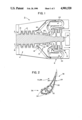
- FIG. 1 is a diagrammatical view of a gas turbine engine incorporating features of the invention.
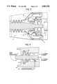
- FIG. 2 is a cross-sectional view of a turbine vane having a cooling means.
- FIG. 3 is a diagrammatical view of a gas turbine engine incorporating an alternate embodiment of the invention.
- FIG. 4 is an enlarge cross-sectional diagrammatical view of a portion of a coolant compressor.
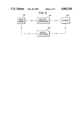
- FIG. 5 is a block diagram of the control system for a coolant compressor using a sensor, micro-processor and drive means.
- FIG. 1 there is shown a diagrammatical view of a gas turbine engine 2 incorporating features of the invention.
- the gas turbine engine 2 generally has four main sections; a main compressor section 4, a second coolant compressor section 6, a combustion section 8, and a turbine section 10.
- the first main compressor section 4 is located in the forward portion of the engine 2 and generally comprises two main air interaction members; stationary stator vanes 12 and rotatable compressor blades 14.
- the main compressor section 4, in this embodiment, can generally be described as having four compressor stages with each stage comprising a wheel or ring-like set of stationary stator vanes 12 and a rotatable wheel of compressor blades 14. Although this embodiment shows only a single axial flow compressor assembly having four stages in the main compressor section 4, the main compressor section 4 may have any number of stages or more than one axial compressor assembly or a centrifugal compressor assembly.
- the main compressor section 4 communicates with an air inlet 16.
- the air inlet 16 allows air located outside the engine 2 to enter into the main compressor section 6 as shown by flow arrows A.
- the main compressor section 4 by revolving the compressor blades 14, can draw air into the engine 2 and compress the air into a smaller volume which in turn pressurizes the air.
- the main compressor section 4 produces a pressurized or compressed main core or flow path of gas for further flow through the engine 2.
- a diffuser housing 18 which acts as a conduit to transport the compressed core of air from the main compressor 4 to the combustion section 8.
- a second conduit 20 is provided for bleeding or redirecting a portion of the main core of compressed air for use as a coolant in the turbine section 10 of the engine 2.
- the combustion section 8 generally comprises a series of combustors 22.
- the main core of compressed air is pushed by new inlet air and the main compressor section 4 into the combustors 22.
- the air in the combustors is mixed with fuel and burned to increase the temperature of the gases.
- the hot gases are allowed to exit the combustors 22 into the turbine section 10 of the engine 2.
- the turbine section 10 generally comprises stationary stator vanes 24 and rotatably mounted turbine blades 26.
- the general function of the turbine section 10 is to drive the compressor and accessories, and in the case of a turboprop engine, the propeller, by extracting a portion of the pressure and kinetic energy from the high-temperature combustion gases. To accomplish this function, the turbine blades 26 are connected to a main drive shaft 28.
- the main drive shaft 28 also has the compressor blades 14 of the main compressor section 4 connected thereto.
- FIG. 2 there is shown a cross-sectional view of a stator vane 24 in the turbine section 10. Because the exiting main core of gases from the combustion section 8 have a relatively high temperature, portions of the turbine section 10 must be cooled to prevent potential damage from these relatively hot gases. Although the invention will be described in use with the vane 24 shown in FIG. 2, it is to be understood that the present invention can be used for all portions of the turbine section 10 including the turbine blades 26.
- the vane 24 uses three types of cooling methods to prevent damage from the combustion gases. All three methods, however, use the bleed air which has been bled from the main core of compressed air before the combustors 22.
- the vane 24 comprises a housing 25 having a plurality of conduits 30 traveling therethrough. Compressed air is supplied to the conduits 30 by a suitable conduit means (not shown) from the coolant compressor section 6 and travels therethrough absorbing heat via convection. The heated coolant air is allowed to exit the vane 24 and thereby cools the vane 24.
- the conduits 30 also have suitable heat transfer members 32 located therein to allow for impingement cooling.
- Film cooling is also provided in this embodiment in both a leading edge 36 and trailing edge 38 of the vane 24.
- apertures 34 are provided between the conduits 30 and the exterior of the vane 24 at both the leading edge 36 and the trailing edge 38.
- the compressed air coolant, located in the conduits 30 having apertures 34, can thus exit the vane 24 via the apertures 34.
- the coolant exited at the apertures 34 is made to flow along the outside surface of the vane 24 by the flow of the hot combustion gases therearound.
- the coolant thus forms an insulating blanket of cooler air between the vane 24 and the hot gases.
- Similar cooling can also be provided for the turbine blades 26 and other turbine parts.
- the compressed air coolant which is supplied to the turbine section 10, as described above, is bled from the main core of compressed air exited from the main compressor section 4 to form a second core or flow path of coolant gas.
- the second compressor section 6 is generally provided for further compressing or pressurizing the coolant gas separate and apart from the main core of gas traveling to and through the combustors 22.
- the coolant compressor section 6, in this embodiment, generally comprises an axial flow compressor assembly 40 having two stages of stationary stator vanes 42 and rotatable compressor blades 44. However, any number of stages can be provided.
- the compressor assembly may be a centrifugal compressor.
- the compressor blades 44 are connected to the main drive shaft 28 such that the turbine section 10 and drive shaft 28 drive both the main compressor section 4 and the coolant compressor section 6.
- the conduits 20 provides a path for the bleed air, diverted from the main core of compressed air via bleed valves (not shown), to access the coolant compressor section 6.
- the bleed air upon entering the coolant compressor section 6, can be compressed or pressurized to a higher degree than the main core of compressed air traveling to and through the combustors 22.
- the coolant compressor section 6 acts on the bleed air similar to the air compressors known in the art whereby both aerodynamic and thermodynamic principles allow the air to be compressed without incurring a substantial temperature rise.
- a coolant delivery conduit 46 is provided to define a path for the increased pressure bleed air to access the turbine assembly 10.
- the coolant is delivered to conduits 30 in the stator vanes 24 as shown in FIG. 2.
- the coolant is allowed to exit the vane 24 at the apertures 34 in the leading edge 36 of the vane.
- the combustion gases passing around the vane 24 are prevented from entering the apertures 34 because the coolant in the vane 24 has a higher pressure than the combustion gases surrounding the vane and therefore prevents damage to the vane 24 which might otherwise occur by the entry of combustion gases into the vane via the apertures 34.
- air is taken from the inlet 16 and compressed via the main compressor section 4.
- the exiting compressed air from the compressor section 4 takes two paths.
- a first main path is provided to the combustors 22 in the combustion section 8.
- a second bleed air path is provided to the coolant compressor section 6.
- the air in the first path is mixed with fuel in the combustors 22 and burned.
- the hot gases from the combustors are allowed to exit the engine via the turbine section 10.
- the air in the second path enters the coolant compressor section 6 and is additionally compressed.
- the increased pressure coolant is then provided to the turbine assembly 10 to provide cooling to the components of the assembly 10.
- the coolant compressor section 6 comprises two compressors 48 and 49 which are independently driven by accessory drive shafts (not shown). Although two separate compressors 48 and 49 are shown in this embodiment, any number of separate compressors can be used.
- FIG. 4 a diagrammatical cross-sectional view of one of the coolant compressors 48 of FIG. 3 is shown. Bleed air is transported to the compressor 48 via the bleed conduit 20.
- the compressor 48 has a shaft 50 having compressor blades 52 connected thereto.
- Stator vanes 54 are provided with a housing 56 which communicates with the bleed air conduit 20 and the coolant delivery conduit 46.
- the bleed air is transported to the compressor 48 via conduit 20 where it is compressed and delivered to the turbine section 10 by the coolant conduit 46.
- the compressor shaft 50 is connected to a suitable drive means 62 (not shown) which can turn the shaft 50 about its axis and thereby revolve the compressor blades 52 to compress the coolant.
- the compressor 48 is also provided with a sensor 58 for sensing the pressure of the coolant air as it exits the compressor 48.
- the sensor is connected to a suitable control means, such as a micro-processor 60 which can receive information from the sensor 58 and can adjust the speed of the shaft 50 to thus control the pressure of the coolant.
- the sensor 58 can determine the coolant pressure being produced by the coolant compressor 48.
- the sensor 58 can send information to the micro-processor 60.
- the micro-processor 60 can regulate the drive means 62 which drives the compressor 48. In the event the coolant pressure is too low, the micro-processor 60 can sense this via the sensor 58 and can increase the power to the drive means 62 thereby increasing the rate of compression by the compressor 48. In the event the coolant pressure is too high, the micro-processor 60 can sense this via the sensor 58 and can decrease the power to the drive means 62 thereby decreasing the rate of compression by the compressor 48.
- the pressure of the coolant gas can be regulated such that the compressor operates efficiently and without substantial risk of insufficient coolant gas pressure.
- the bleed conduit 20 is shown positioned after a radial bend in the diffuser housing 18.
- the bleed air is diverted from the housing 18 with a substantial amount of any contaminate particles having been centrifuged away from the inlet to the conduit 20.
- the bleed air is relatively clean and will therefore not have foreign particles clog or block the apertures 34 in the vanes 24.
- any suitable means can be used to conduit the bleed air to the coolant compressor section 6.
- Any suitable means can be used to conduit the increased pressure coolant to various parts in the turbine section 10.
- Any type of suitable compressor means can be used as the coolant compressor.
Abstract
Description
Claims (14)
Priority Applications (1)
| Application Number | Priority Date | Filing Date | Title |
|---|---|---|---|
| US07/231,774 US4901520A (en) | 1988-08-12 | 1988-08-12 | Gas turbine pressurized cooling system |
Applications Claiming Priority (1)
| Application Number | Priority Date | Filing Date | Title |
|---|---|---|---|
| US07/231,774 US4901520A (en) | 1988-08-12 | 1988-08-12 | Gas turbine pressurized cooling system |
Publications (1)
| Publication Number | Publication Date |
|---|---|
| US4901520A true US4901520A (en) | 1990-02-20 |
Family
ID=22870599
Family Applications (1)
| Application Number | Title | Priority Date | Filing Date |
|---|---|---|---|
| US07/231,774 Expired - Fee Related US4901520A (en) | 1988-08-12 | 1988-08-12 | Gas turbine pressurized cooling system |
Country Status (1)
| Country | Link |
|---|---|
| US (1) | US4901520A (en) |
Cited By (43)
| Publication number | Priority date | Publication date | Assignee | Title |
|---|---|---|---|---|
| EP0435770A1 (en) * | 1989-12-28 | 1991-07-03 | Societe Nationale D'etude Et De Construction De Moteurs D'aviation "Snecma" | Aircooled turbomachine and method for cooling of this turbo machine |
| WO1993007372A1 (en) * | 1991-10-11 | 1993-04-15 | United Technologies Corporation | Gas turbine cycle |
| US5205721A (en) * | 1991-02-13 | 1993-04-27 | Nu-Tech Industries, Inc. | Split stator for motor/blood pump |
| US5231825A (en) * | 1990-04-09 | 1993-08-03 | General Electric Company | Method for compressor air extraction |
| US5311734A (en) * | 1991-09-11 | 1994-05-17 | General Electric Company | System and method for improved engine cooling in conjunction with an improved gas bearing face seal assembly |
| EP0656468A1 (en) * | 1993-12-03 | 1995-06-07 | Westinghouse Electric Corporation | Gas turbine vane cooling system |
| US5581996A (en) * | 1995-08-16 | 1996-12-10 | General Electric Company | Method and apparatus for turbine cooling |
| WO1997023715A2 (en) * | 1995-12-21 | 1997-07-03 | Siemens Aktiengesellschaft | Process for operating a gas turbine and gas turbine operating in this way |
| WO1997049902A1 (en) * | 1996-06-24 | 1997-12-31 | Westinghouse Electric Corporation | On-board auxiliary compressor for combustion turbine cooling air supply |
| WO1998013584A1 (en) * | 1996-09-26 | 1998-04-02 | Siemens Aktiengesellschaft | Method of compensating pressure loss in a cooling air guide system in a gas turbine plant |
| DE19644378A1 (en) * | 1996-10-25 | 1998-04-30 | Asea Brown Boveri | Air cooling system for axial gas turbines |
| US5819524A (en) * | 1996-10-16 | 1998-10-13 | Capstone Turbine Corporation | Gaseous fuel compression and control system and method |
| US5899673A (en) * | 1996-10-16 | 1999-05-04 | Capstone Turbine Corporation | Helical flow compressor/turbine permanent magnet motor/generator |
| US5993150A (en) * | 1998-01-16 | 1999-11-30 | General Electric Company | Dual cooled shroud |
| US6000906A (en) * | 1997-09-12 | 1999-12-14 | Alliedsignal Inc. | Ceramic airfoil |
| DE10019437A1 (en) * | 2000-04-19 | 2001-12-20 | Rolls Royce Deutschland | Method and device for cooling the housings of turbines of jet engines |
| EP1245806A1 (en) * | 2001-03-30 | 2002-10-02 | Siemens Aktiengesellschaft | Cooled gas turbine balde |
| US6468051B2 (en) | 1999-04-19 | 2002-10-22 | Steven W. Lampe | Helical flow compressor/turbine permanent magnet motor/generator |
| EP1400669A1 (en) * | 2002-09-23 | 2004-03-24 | Rolls-Royce Deutschland Ltd & Co KG | Gas turbine engine with apparatus for generation of mechanical work for cooling of discs |
| US20050042075A1 (en) * | 2003-08-22 | 2005-02-24 | Siemens Westinghouse Power Corporation | Differential pressure sensing system for airfoils usable in turbine engines |
| US20050268619A1 (en) * | 2004-06-08 | 2005-12-08 | Ress Robert A Jr | Method and apparatus for increasing the pressure of cooling fluid within a gas turbine engine |
| US20060263216A1 (en) * | 2005-05-23 | 2006-11-23 | Siemens Westinghouse Power Corporation | Detection of gas turbine airfoil failure |
| US20070278879A1 (en) * | 2006-06-02 | 2007-12-06 | Christopher Anthony Kaminski | Methods and apparatus for using an electrical machine to transport fluids through a pipeline |
| DE102009003408A1 (en) | 2008-02-01 | 2009-08-06 | General Electric Co. | Apparatus and related methods for cooling turbines |
| US20110016878A1 (en) * | 2009-07-24 | 2011-01-27 | General Electric Company | Systems and Methods for Gas Turbine Combustors |
| US20120060506A1 (en) * | 2010-09-10 | 2012-03-15 | Rolls-Royce Plc | Gas turbine engine |
| US20120102969A1 (en) * | 2010-10-28 | 2012-05-03 | Wagner Joel H | Centrifugal compressor with bleed flow splitter for a gas turbine engine |
| US20130280046A1 (en) * | 2011-01-11 | 2013-10-24 | Snecma | Bypass turbojet |
| DE102012208263A1 (en) * | 2012-05-16 | 2013-11-21 | Rolls-Royce Deutschland Ltd & Co Kg | Compressor device for turbomachine of jet engine, has secondary compressor that is designed such that air withdrawn after last compressor stage is supplied to secondary compressor, which is driven by gearbox of auxiliary device carrier |
| US9091173B2 (en) | 2012-05-31 | 2015-07-28 | United Technologies Corporation | Turbine coolant supply system |
| US20150323186A1 (en) * | 2014-05-09 | 2015-11-12 | United Technologies Corporation | Cooled fuel injector system for a gas turbine engine and method for operating the same |
| US9228441B2 (en) | 2012-05-22 | 2016-01-05 | United Technologies Corporation | Passive thermostatic valve |
| US20170051678A1 (en) * | 2015-08-18 | 2017-02-23 | General Electric Company | Mixed flow turbocore |
| US20170184027A1 (en) * | 2015-12-29 | 2017-06-29 | General Electric Company | Method and system for compressor and turbine cooling |
| US10041407B2 (en) | 2011-03-29 | 2018-08-07 | General Electric Company | System and method for air extraction from gas turbine engines |
| US10240470B2 (en) | 2013-08-30 | 2019-03-26 | United Technologies Corporation | Baffle for gas turbine engine vane |
| US10400795B2 (en) | 2016-07-20 | 2019-09-03 | General Electric Company | High pressure cyclonic separator for turbomachinery |
| US10400670B2 (en) | 2016-06-15 | 2019-09-03 | General Electric Company | Inlet particle separator for a turbine engine |
| US10415465B2 (en) * | 2017-12-21 | 2019-09-17 | United Technologies Corporation | Axial compressor with inter-stage centrifugal compressor |
| US10578028B2 (en) | 2015-08-18 | 2020-03-03 | General Electric Company | Compressor bleed auxiliary turbine |
| US10695704B2 (en) | 2016-07-20 | 2020-06-30 | General Electric Company | Multi-station debris separation system |
| US10724436B2 (en) | 2016-01-21 | 2020-07-28 | General Electric Company | Inlet particle separator for a turbine engine |
| US10830138B2 (en) | 2016-07-20 | 2020-11-10 | General Electric Company | Fine debris multi-stage separation system |
Citations (14)
| Publication number | Priority date | Publication date | Assignee | Title |
|---|---|---|---|---|
| US12317A (en) * | 1855-01-30 | Cakeiage-wheel | ||
| US2618433A (en) * | 1948-06-23 | 1952-11-18 | Curtiss Wright Corp | Means for bleeding air from compressors |
| US2672013A (en) * | 1950-06-30 | 1954-03-16 | Curtiss Wright Corp | Gas turbine cooling system |
| US2940660A (en) * | 1956-04-11 | 1960-06-14 | Alfred M Caddell | Compressor with air cooler between stages |
| US3663118A (en) * | 1970-06-01 | 1972-05-16 | Gen Motors Corp | Turbine cooling control |
| US4063851A (en) * | 1975-12-22 | 1977-12-20 | United Technologies Corporation | Coolable turbine airfoil |
| US4086757A (en) * | 1976-10-06 | 1978-05-02 | Caterpillar Tractor Co. | Gas turbine cooling system |
| US4153386A (en) * | 1974-12-11 | 1979-05-08 | United Technologies Corporation | Air cooled turbine vanes |
| US4162136A (en) * | 1974-04-05 | 1979-07-24 | Rolls-Royce Limited | Cooled blade for a gas turbine engine |
| US4217755A (en) * | 1978-12-04 | 1980-08-19 | General Motors Corporation | Cooling air control valve |
| US4236869A (en) * | 1977-12-27 | 1980-12-02 | United Technologies Corporation | Gas turbine engine having bleed apparatus with dynamic pressure recovery |
| US4297077A (en) * | 1979-07-09 | 1981-10-27 | Westinghouse Electric Corp. | Cooled turbine vane |
| US4312624A (en) * | 1980-11-10 | 1982-01-26 | United Technologies Corporation | Air cooled hollow vane construction |
| US4461612A (en) * | 1982-04-27 | 1984-07-24 | Rolls-Royce Limited | Aerofoil for a gas turbine engine |
-
1988
- 1988-08-12 US US07/231,774 patent/US4901520A/en not_active Expired - Fee Related
Patent Citations (14)
| Publication number | Priority date | Publication date | Assignee | Title |
|---|---|---|---|---|
| US12317A (en) * | 1855-01-30 | Cakeiage-wheel | ||
| US2618433A (en) * | 1948-06-23 | 1952-11-18 | Curtiss Wright Corp | Means for bleeding air from compressors |
| US2672013A (en) * | 1950-06-30 | 1954-03-16 | Curtiss Wright Corp | Gas turbine cooling system |
| US2940660A (en) * | 1956-04-11 | 1960-06-14 | Alfred M Caddell | Compressor with air cooler between stages |
| US3663118A (en) * | 1970-06-01 | 1972-05-16 | Gen Motors Corp | Turbine cooling control |
| US4162136A (en) * | 1974-04-05 | 1979-07-24 | Rolls-Royce Limited | Cooled blade for a gas turbine engine |
| US4153386A (en) * | 1974-12-11 | 1979-05-08 | United Technologies Corporation | Air cooled turbine vanes |
| US4063851A (en) * | 1975-12-22 | 1977-12-20 | United Technologies Corporation | Coolable turbine airfoil |
| US4086757A (en) * | 1976-10-06 | 1978-05-02 | Caterpillar Tractor Co. | Gas turbine cooling system |
| US4236869A (en) * | 1977-12-27 | 1980-12-02 | United Technologies Corporation | Gas turbine engine having bleed apparatus with dynamic pressure recovery |
| US4217755A (en) * | 1978-12-04 | 1980-08-19 | General Motors Corporation | Cooling air control valve |
| US4297077A (en) * | 1979-07-09 | 1981-10-27 | Westinghouse Electric Corp. | Cooled turbine vane |
| US4312624A (en) * | 1980-11-10 | 1982-01-26 | United Technologies Corporation | Air cooled hollow vane construction |
| US4461612A (en) * | 1982-04-27 | 1984-07-24 | Rolls-Royce Limited | Aerofoil for a gas turbine engine |
Cited By (65)
| Publication number | Priority date | Publication date | Assignee | Title |
|---|---|---|---|---|
| EP0435770A1 (en) * | 1989-12-28 | 1991-07-03 | Societe Nationale D'etude Et De Construction De Moteurs D'aviation "Snecma" | Aircooled turbomachine and method for cooling of this turbo machine |
| US5163285A (en) * | 1989-12-28 | 1992-11-17 | Societe Nationale D'etude Et De Construction De Moteurs D'aviation "S.N.E.C.M.A." | Cooling system for a gas turbine |
| US5231825A (en) * | 1990-04-09 | 1993-08-03 | General Electric Company | Method for compressor air extraction |
| US5205721A (en) * | 1991-02-13 | 1993-04-27 | Nu-Tech Industries, Inc. | Split stator for motor/blood pump |
| US5311734A (en) * | 1991-09-11 | 1994-05-17 | General Electric Company | System and method for improved engine cooling in conjunction with an improved gas bearing face seal assembly |
| WO1993007372A1 (en) * | 1991-10-11 | 1993-04-15 | United Technologies Corporation | Gas turbine cycle |
| EP0656468A1 (en) * | 1993-12-03 | 1995-06-07 | Westinghouse Electric Corporation | Gas turbine vane cooling system |
| US5581996A (en) * | 1995-08-16 | 1996-12-10 | General Electric Company | Method and apparatus for turbine cooling |
| WO1997023715A2 (en) * | 1995-12-21 | 1997-07-03 | Siemens Aktiengesellschaft | Process for operating a gas turbine and gas turbine operating in this way |
| WO1997023715A3 (en) * | 1995-12-21 | 1997-09-04 | Siemens Ag | Process for operating a gas turbine and gas turbine operating in this way |
| WO1997049902A1 (en) * | 1996-06-24 | 1997-12-31 | Westinghouse Electric Corporation | On-board auxiliary compressor for combustion turbine cooling air supply |
| WO1998013584A1 (en) * | 1996-09-26 | 1998-04-02 | Siemens Aktiengesellschaft | Method of compensating pressure loss in a cooling air guide system in a gas turbine plant |
| US5819524A (en) * | 1996-10-16 | 1998-10-13 | Capstone Turbine Corporation | Gaseous fuel compression and control system and method |
| US5899673A (en) * | 1996-10-16 | 1999-05-04 | Capstone Turbine Corporation | Helical flow compressor/turbine permanent magnet motor/generator |
| DE19644378A1 (en) * | 1996-10-25 | 1998-04-30 | Asea Brown Boveri | Air cooling system for axial gas turbines |
| US6000906A (en) * | 1997-09-12 | 1999-12-14 | Alliedsignal Inc. | Ceramic airfoil |
| US5993150A (en) * | 1998-01-16 | 1999-11-30 | General Electric Company | Dual cooled shroud |
| US6468051B2 (en) | 1999-04-19 | 2002-10-22 | Steven W. Lampe | Helical flow compressor/turbine permanent magnet motor/generator |
| DE10019437A1 (en) * | 2000-04-19 | 2001-12-20 | Rolls Royce Deutschland | Method and device for cooling the housings of turbines of jet engines |
| US6625989B2 (en) | 2000-04-19 | 2003-09-30 | Rolls-Royce Deutschland Ltd & Co Kg | Method and apparatus for the cooling of jet-engine turbine casings |
| EP1245806A1 (en) * | 2001-03-30 | 2002-10-02 | Siemens Aktiengesellschaft | Cooled gas turbine balde |
| US6672074B2 (en) | 2001-03-30 | 2004-01-06 | Siemens Aktiengesellschaft | Gas turbine |
| EP1400669A1 (en) * | 2002-09-23 | 2004-03-24 | Rolls-Royce Deutschland Ltd & Co KG | Gas turbine engine with apparatus for generation of mechanical work for cooling of discs |
| US20040112064A1 (en) * | 2002-09-23 | 2004-06-17 | Winfried-Hagen Friedl | Gas turbine with device for extracting work from disk cooling air |
| US20050042075A1 (en) * | 2003-08-22 | 2005-02-24 | Siemens Westinghouse Power Corporation | Differential pressure sensing system for airfoils usable in turbine engines |
| US6942450B2 (en) | 2003-08-22 | 2005-09-13 | Siemens Westinghouse Power Corporation | Differential pressure sensing system for airfoils usable in turbine engines |
| US20050268619A1 (en) * | 2004-06-08 | 2005-12-08 | Ress Robert A Jr | Method and apparatus for increasing the pressure of cooling fluid within a gas turbine engine |
| US7225624B2 (en) * | 2004-06-08 | 2007-06-05 | Allison Advanced Development Company | Method and apparatus for increasing the pressure of cooling fluid within a gas turbine engine |
| US20060263216A1 (en) * | 2005-05-23 | 2006-11-23 | Siemens Westinghouse Power Corporation | Detection of gas turbine airfoil failure |
| US7412320B2 (en) | 2005-05-23 | 2008-08-12 | Siemens Power Generation, Inc. | Detection of gas turbine airfoil failure |
| US20070278879A1 (en) * | 2006-06-02 | 2007-12-06 | Christopher Anthony Kaminski | Methods and apparatus for using an electrical machine to transport fluids through a pipeline |
| US7579724B2 (en) * | 2006-06-02 | 2009-08-25 | General Electric Company | Methods and apparatus for using an electrical machine to transport fluids through a pipeline |
| DE102009003408A1 (en) | 2008-02-01 | 2009-08-06 | General Electric Co. | Apparatus and related methods for cooling turbines |
| US8096747B2 (en) | 2008-02-01 | 2012-01-17 | General Electric Company | Apparatus and related methods for turbine cooling |
| US20090196736A1 (en) * | 2008-02-01 | 2009-08-06 | Ajit Singh Sengar | Apparatus and related methods for turbine cooling |
| CN101963101B (en) * | 2009-07-24 | 2014-08-20 | 通用电气公司 | Systems and methods for gas turbine combustors |
| US20110016878A1 (en) * | 2009-07-24 | 2011-01-27 | General Electric Company | Systems and Methods for Gas Turbine Combustors |
| CN101963101A (en) * | 2009-07-24 | 2011-02-02 | 通用电气公司 | Systems and methods for gas turbine combustors |
| US8474266B2 (en) * | 2009-07-24 | 2013-07-02 | General Electric Company | System and method for a gas turbine combustor having a bleed duct from a diffuser to a fuel nozzle |
| US8893511B2 (en) | 2009-07-24 | 2014-11-25 | General Electric Company | Systems and methods for a gas turbine combustor having a bleed duct |
| US20120060506A1 (en) * | 2010-09-10 | 2012-03-15 | Rolls-Royce Plc | Gas turbine engine |
| US9103281B2 (en) * | 2010-09-10 | 2015-08-11 | Rolls-Royce Plc | Gas turbine engine havinga rotatable off-take passage in a compressor section |
| US20120102969A1 (en) * | 2010-10-28 | 2012-05-03 | Wagner Joel H | Centrifugal compressor with bleed flow splitter for a gas turbine engine |
| US8935926B2 (en) * | 2010-10-28 | 2015-01-20 | United Technologies Corporation | Centrifugal compressor with bleed flow splitter for a gas turbine engine |
| US20130280046A1 (en) * | 2011-01-11 | 2013-10-24 | Snecma | Bypass turbojet |
| US9611865B2 (en) * | 2011-01-11 | 2017-04-04 | Snecma | Bypass turbojet |
| US10041407B2 (en) | 2011-03-29 | 2018-08-07 | General Electric Company | System and method for air extraction from gas turbine engines |
| DE102012208263A1 (en) * | 2012-05-16 | 2013-11-21 | Rolls-Royce Deutschland Ltd & Co Kg | Compressor device for turbomachine of jet engine, has secondary compressor that is designed such that air withdrawn after last compressor stage is supplied to secondary compressor, which is driven by gearbox of auxiliary device carrier |
| US9228441B2 (en) | 2012-05-22 | 2016-01-05 | United Technologies Corporation | Passive thermostatic valve |
| US9091173B2 (en) | 2012-05-31 | 2015-07-28 | United Technologies Corporation | Turbine coolant supply system |
| US10240470B2 (en) | 2013-08-30 | 2019-03-26 | United Technologies Corporation | Baffle for gas turbine engine vane |
| US20150323186A1 (en) * | 2014-05-09 | 2015-11-12 | United Technologies Corporation | Cooled fuel injector system for a gas turbine engine and method for operating the same |
| US10400674B2 (en) * | 2014-05-09 | 2019-09-03 | United Technologies Corporation | Cooled fuel injector system for a gas turbine engine and method for operating the same |
| US11280268B2 (en) | 2014-05-09 | 2022-03-22 | Raytheon Technologies Corporation | Cooled fuel injector system for a gas turbine engine and a method for operating the same |
| US20170051678A1 (en) * | 2015-08-18 | 2017-02-23 | General Electric Company | Mixed flow turbocore |
| US10578028B2 (en) | 2015-08-18 | 2020-03-03 | General Electric Company | Compressor bleed auxiliary turbine |
| US10711702B2 (en) * | 2015-08-18 | 2020-07-14 | General Electric Company | Mixed flow turbocore |
| US20170184027A1 (en) * | 2015-12-29 | 2017-06-29 | General Electric Company | Method and system for compressor and turbine cooling |
| US10724436B2 (en) | 2016-01-21 | 2020-07-28 | General Electric Company | Inlet particle separator for a turbine engine |
| US10400670B2 (en) | 2016-06-15 | 2019-09-03 | General Electric Company | Inlet particle separator for a turbine engine |
| US10400795B2 (en) | 2016-07-20 | 2019-09-03 | General Electric Company | High pressure cyclonic separator for turbomachinery |
| US10695704B2 (en) | 2016-07-20 | 2020-06-30 | General Electric Company | Multi-station debris separation system |
| US10830138B2 (en) | 2016-07-20 | 2020-11-10 | General Electric Company | Fine debris multi-stage separation system |
| US11369905B2 (en) | 2016-07-20 | 2022-06-28 | General Electric Company | Multi-station debris separation system |
| US10415465B2 (en) * | 2017-12-21 | 2019-09-17 | United Technologies Corporation | Axial compressor with inter-stage centrifugal compressor |
Similar Documents
| Publication | Publication Date | Title |
|---|---|---|
| US4901520A (en) | Gas turbine pressurized cooling system | |
| US6250061B1 (en) | Compressor system and methods for reducing cooling airflow | |
| US5392614A (en) | Gas turbine engine cooling system | |
| US5317877A (en) | Intercooled turbine blade cooling air feed system | |
| EP2990335B1 (en) | Gas turbine engine | |
| EP0564135B1 (en) | Gas turbine engine cooling system | |
| US8087249B2 (en) | Turbine cooling air from a centrifugal compressor | |
| US5297386A (en) | Cooling system for a gas turbine engine compressor | |
| EP2358978B1 (en) | Apparatus and method for cooling a turbine airfoil arrangement in a gas turbine engine | |
| US6647730B2 (en) | Turbine engine having turbine cooled with diverted compressor intermediate pressure air | |
| US7708519B2 (en) | Vortex spoiler for delivery of cooling airflow in a turbine engine | |
| KR100456491B1 (en) | Fixed vane assembly of a gas turbine engine | |
| EP1167722B1 (en) | A method of cooling a gas turbine engine and gas turbine engine | |
| CA3014977C (en) | Air delivery system for a gas turbine engine | |
| US10107206B2 (en) | High pressure compressor rotor thermal conditioning using discharge pressure air | |
| CA2951812A1 (en) | Method and system for compressor and turbine cooling | |
| EP3032031A1 (en) | Modulated cooled high pressure bleed air for impeller | |
| US11352954B2 (en) | Intercooling systems and methods for aircraft engines | |
| CN110608099A (en) | Gas turbine engine with integrated air cycle machine | |
| US20210062727A1 (en) | System and method for conditioning a fluid using bleed air from a bypass duct of a turbofan engine | |
| US11390386B2 (en) | System and method for increasing bleed air flow to a heat exchanger with a fluid-driven fluid propeller | |
| EP3351767B1 (en) | Intercooled cooling air system with bypass | |
| CN115711160A (en) | Method of cooling turbine blades | |
| WO1997049902A1 (en) | On-board auxiliary compressor for combustion turbine cooling air supply | |
| GB2356671A (en) | Gas turbine engine cooling |
Legal Events
| Date | Code | Title | Description |
|---|---|---|---|
| AS | Assignment |
Owner name: AVCO CORPORATION, 40 WESTMINSTER STREET, PROVIDENC Free format text: ASSIGNMENT OF ASSIGNORS INTEREST.;ASSIGNOR:MINKKINEN, GEORGE;REEL/FRAME:004952/0742 Effective date: 19880715 Owner name: AVCO CORPORATION, 40 WESTMINSTER STREET, PROVIDENC Free format text: ASSIGNMENT OF ASSIGNORS INTEREST.;ASSIGNOR:KOZAK, ANDREW;REEL/FRAME:004952/0740 Effective date: 19880425 |
|
| FEPP | Fee payment procedure |
Free format text: PAYOR NUMBER ASSIGNED (ORIGINAL EVENT CODE: ASPN); ENTITY STATUS OF PATENT OWNER: LARGE ENTITY |
|
| FEPP | Fee payment procedure |
Free format text: PAYER NUMBER DE-ASSIGNED (ORIGINAL EVENT CODE: RMPN); ENTITY STATUS OF PATENT OWNER: LARGE ENTITY Free format text: PAYOR NUMBER ASSIGNED (ORIGINAL EVENT CODE: ASPN); ENTITY STATUS OF PATENT OWNER: LARGE ENTITY |
|
| FPAY | Fee payment |
Year of fee payment: 4 |
|
| AS | Assignment |
Owner name: ALLIEDSIGNAL INC., NEW JERSEY Free format text: ASSIGNMENT OF ASSIGNORS INTEREST;ASSIGNOR:AVCO CORPORATION;REEL/FRAME:007183/0633 Effective date: 19941028 |
|
| REMI | Maintenance fee reminder mailed | ||
| LAPS | Lapse for failure to pay maintenance fees | ||
| FP | Lapsed due to failure to pay maintenance fee |
Effective date: 19980225 |
|
| STCH | Information on status: patent discontinuation |
Free format text: PATENT EXPIRED DUE TO NONPAYMENT OF MAINTENANCE FEES UNDER 37 CFR 1.362 |