US4901711A - Drill guide - Google Patents
Drill guide Download PDFInfo
- Publication number
- US4901711A US4901711A US07/290,423 US29042388A US4901711A US 4901711 A US4901711 A US 4901711A US 29042388 A US29042388 A US 29042388A US 4901711 A US4901711 A US 4901711A
- Authority
- US
- United States
- Prior art keywords
- drill
- guide
- traveling
- rails
- drill guide
- Prior art date
- Legal status (The legal status is an assumption and is not a legal conclusion. Google has not performed a legal analysis and makes no representation as to the accuracy of the status listed.)
- Expired - Lifetime
Links
Images
Classifications
-
- A—HUMAN NECESSITIES
- A61—MEDICAL OR VETERINARY SCIENCE; HYGIENE
- A61B—DIAGNOSIS; SURGERY; IDENTIFICATION
- A61B17/00—Surgical instruments, devices or methods, e.g. tourniquets
- A61B17/16—Bone cutting, breaking or removal means other than saws, e.g. Osteoclasts; Drills or chisels for bones; Trepans
- A61B17/17—Guides or aligning means for drills, mills, pins or wires
- A61B17/1714—Guides or aligning means for drills, mills, pins or wires for applying tendons or ligaments
-
- A—HUMAN NECESSITIES
- A61—MEDICAL OR VETERINARY SCIENCE; HYGIENE
- A61B—DIAGNOSIS; SURGERY; IDENTIFICATION
- A61B17/00—Surgical instruments, devices or methods, e.g. tourniquets
- A61B17/16—Bone cutting, breaking or removal means other than saws, e.g. Osteoclasts; Drills or chisels for bones; Trepans
- A61B17/17—Guides or aligning means for drills, mills, pins or wires
- A61B17/1739—Guides or aligning means for drills, mills, pins or wires specially adapted for particular parts of the body
- A61B17/1764—Guides or aligning means for drills, mills, pins or wires specially adapted for particular parts of the body for the knee
Definitions
- the invention relates to surgical devices and in particular to devices for use in knee reconstructive surgery that enables a surgeon to form a tunnel through the side of a patient's knee to exactly intersect an anterior or posterior cruciate ligament tunnel that has been formed through the knee.
- tibial and femoral tunnel sections As the ligament tunnel through the respective femoral and tibial points of ligament origin.
- Such tunnels can be formed as shown in patents and a new patent application, respectively, of the present inventors, entitled, "Ligament Attachment Method and Apparatus", U.S. Pat. No. 4,772,286; and "Apparatus and Procedure for Verifying Isometric Ligament Positioning".
- the ligament tunnel is to receive a biologic or prosthetic ligament installed therein, the installed ligament to be maintained in a tension state across the intra articular knee joint during healing.
- the present invention in a drill guide is arranged to reference a straight "K" wire to receive the present invention fitted thereover.
- the present invention in a drill guide is for use for guiding the drilling of a hole into the side of the femur or tibia so as to intersect the cruciate ligament tunnel.
- a coupling device such as a screw can be turned into the side of a ligament end coupling that has been turned into a tapped end of the prepared ligament tunnel section, or into the ligament itself, providing an increased pull out strength to that ligament.
- 2,078,528, all show arrangements for drilling cruciate ligament tunnel sections through the intra articular joint from a point on the tibial or femoral cortex to intersect the end of a guide that is positioned on a cruciate ligament point of origin.
- patents to Seedholm, et al., U.S. Pat. No. 4,668,233, and a European Patent Application 0126529 show a prosthetic ligament and drill guide for preparing tibial and femoral tunnel sections.
- Another object of the present invention is to provide a drill guide for use in a surgical procedure for guiding from the side, a drill that is turned into a patient's knee, to intersect, at a right angle, a specific point of location along a prepared cruciate ligament tunnel.
- Still another object of the present invention is to provide a drill guide that references a straight "K" wire, or the like, that has been installed through aligned cruciate ligament tunnel sections, to enable a surgeon, from any point around the knee, from one side of the leg to the other, to easily and accurately drill a lateral hole or tunnel so as to exactly intersect a point along the aligned cruciate ligament tunnel sections.
- the present invention is in a drill guide that is intended for use in a knee surgical procedure where a cruciate ligament tunnel has been formed through the knee, exiting both the femoral and tibial cortexes.
- the drill guide of the present invention is for mounting to a "K" wire, or the like, that has been fitted through the ligament tunnel or tunnel sections to guide a surgeon drilling a lateral passage or tunnel from a point that is without the knee. Which drill can be from any point around an arc from one side of the leg knee area to the other, to exactly intersect, at essentially a right angle, the cruciate ligament tunnel.
- the drill guide is arranged for installation onto the ends of a "K" wire that has been passed through the cruciate ligament tunnel, exiting both the femoral and tibial cortexes.
- the drill guide fits the "K” wire through aligned guide cylinders and may include a sleeve for telescoping therein to receive the "K” wire passed therethrough to provide a close fit that allows for axial rotation of the drill guide on that "K” wire.
- the guide cylinders are mounted on brackets, spaced apart on parallel rails, one of which brackets is arranged to slide along the parallel rails, and can be removed therefrom for mounting the "K” wire.
- a trolley of the drill guide is arranged to travel along the rails, between the brackets.
- the trolley includes a body that is arranged to receive a removable drill sleeve for replaceable mounting thereto, that extends at a right or normal angle to the rails.
- the trolley can be positioned at any point along the rails and includes, as does the traveling bracket, a friction locking arrangement for releasably holding it in place.
- the cylindrical drill sleeve is removable by turning it into and out of the trolley body for accommodating different diameters of barrels over a range of drill sizes for fitting therethrough.
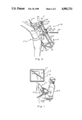
- FIG. 1 shows a surgeon seated before a patient's flexed knee observing a fluoroscopic monitor and drilling, from the tibial tuberosity, an anterior cruciate ligament tunnel, the drill passed through the intra articular joint and both the cruciate ligament points of origin and the tibial and femoral cortexes;
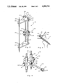
- FIG. 2 shows a slide elevation view perspective of a "K" wire installed in the ligament tunnel of FIG. 1 with aligned guide cylinders of brackets of the drill guide of the present invention shown telescoped thereover, the brackets shown mounted on parallel rails with a trolley shown mounted to travel along the parallel rails, and showing a drill aligned for fitting through a drill sleeve barrel that is aligned at approximately a right angle to the "K" wire;
- FIG. 3 shows a side elevation perspective view of the drill guide and "K" wire of FIG. 2 removed from the knee;
- FIG. 4 shows an enlarged view of the trolley of FIG. 3 arranged on sections of the drill guide rails and shows the drill sleeve exploded therefrom;
- FIG. 5 shows an allograft anterior cruciate ligament fitted into the prepared tunnel with right angle holes shown intersecting that tunnel and showing screws aligned for turning therein.
- FIG. 1 shows a surgeon 10 seated in front of a patient's knee 11 practicing an arthroscopic surgical procedure for replacing the patient's anterior cruciate ligament with an allograft or prosthetic ligament.
- the surgeon observes, on a fluoroscopic monitor 12, the passage of a drill turned by a driver 15 through the tibial tuberosity into the knee 11 intra articular joint, passing through both the femoral and tibial points of ligament attachment or origin, and the drill shown as having exited the femur anterolateral cortex.
- the driver 15 removed and with a "K" wire 13, fitted through knee 11, the "K" wire ends will extend beyond the tibial tuberosity and femoral anterolateral cortex.
- a drill guide 20 of the present invention can then be fitted thereover, as illustrated in FIG. 2.
- FIGS. 2 and 3 show the drill guide 20 as preferably consisting of a pair of identical spaced apart parallel rails 21.
- Each rail 21 is fixed at its one end to one of two base corners of a stationary isosceles triangular shaped bracket 22, hereinafter referred to as stationary bracket.
- the stationary bracket at its apex includes an guide cylinder 23 that is open longitudinally, is secured to extend at a right angle therethrough, and is parallel to the rails 21.
- the opposite rail 21 ends are preferably rounded at 21a and receive a traveling isosceles triangular shaped bracket 25, hereinafter referred to as traveling bracket, journaled thereover.
- the traveling bracket 25 also includes an open guide cylinder that, like guide cylinder 23, is open longitudinally and is secured through the traveling brackets apex, such that the longitudinal openings through the respective open guide cylinders 23 and 26 are to align with each other to accommodate the "K" wire 13 fitted therethrough.
- sleeves 24 can be installed on the guide cylinders longitudinal passages to provide a close fit to the "K" wire while still allowing the drill guide to rotate freely thereon.
- the traveling bracket 25 is holed at 27, proximate to each of the triangle base corners, to accommodate rail rounded ends 21a fitted therethrough.
- Set screws 28 are provided for locking the traveling bracket 25 in place on the rails 21.
- the set screws 28 are turned into threaded lateral holes that are formed from the hypotenuse sides of that traveling bracket, proximate to their junctions with the base, to intersect holes 27. Shown in FIGS. 2 and 3, the set screws 28 include both threaded shafts for turning into the laterally threaded holes, and enlarged head ends 29 that are to be manually turned. So arranged, by turning the set screw 28 end out of engagement with the rails 21, the traveling bracket 25 is released and can be slid therefrom. This allows the guide cylinder 26 to be slid off from or fitted over a "K" wire 13 end. This arrangement provides for mounting the drill guide 20 to the "K" wire 13, as shown best in FIG. 2.
- Trolley 30 is shown to consist of a rectangular slide body 31 that is holed through and between opposite parallel top and bottom faces as shown best in FIG. 4 to pass rail sleeves 32 fitted therethrough that accommodate the support rails 21 journaled therethrough.
- the slide body 31 is also holed and tapped at opposite ends, each hole to receive a locking screw 34 turned therein.
- Each of which locking screws 34 includes a broad head end 35 that is for manual turning to move a screw end thereof, not shown, into engagement with the side of a rail sleeve 32.
- Each locking screw 34 is used to lock the trolley 30 to a rail 21.
- each rail sleeve 32 may be holed opposite to the end of locking screw 34, such that the locking screw end will pass through the rail sleeve and engage the side of rail 21.
- the rail sleeve 32 may be a linear bearing that is holed to accommodate the locking screw end traveling therethrough.
- the rail sleeve 32 may be splint longitudinally, the locking screw end to butt thereagainst so as to cause that rail sleeve to flex into engagement with the side of rail 21.
- the trolley 30 is free to move along and lock to rails 21, between the stationary and traveling brackets, 22 and 25, respectively.
- the trolley function is to align and guide a drill 44 for turning through a drill sleeve 36 that is mounted to the trolley.
- the drill sleeve 36 is fitted through a support tube 38 that is mounted through a lateral hole 37 formed through the trolley slide body 31.
- the open support tube 38 includes internal threads 39 that are formed in one end to accommodate threads 43 of a collar of a barrel 40 portion of drill sleeve 36 turned therein.
- the drill sleeve is shown to include a longitudinal hole 41 that is formed therethrough as a barrel, and has a head end 42 for manual turning.
- the drill sleeve barrel longitudinal hole has a diameter to accommodate a certain size of drill 44.
- the threaded collar 43 is arranged adjacent to the drill sleeve head end 42 for turning in the support tube internal threads 39. So arranged, the drill sleeve 36 is easily mounted to and demounted from the trolley 30.
- the longitudinal hole 41 of the drill sleeve functions as a barrel to exactly point at the "K" wire 13 and drill sleeve 36 having different diameters of longitudinal holes 41 and accommodates different sizes of drills 44 turned into the knee at any position of trolley 30 along rails 21 and around the knee.
- FIG. 2 shows the drill guide 20 of the present invention mounted to the "K" wire 13 with a drill 44 shown aligned for turning through the longitudinal hole 41 of the drill sleeve 36.
- Which drill 44 is for turning into the distal femur or proximal tibia to exactly intersect, at essentially a right angle, the anterior cruciate ligament tunnel, as shown in FIG. 1.
- FIG. 5 shows the patient's knee 11 with the anterior cruciate ligament tunnel having been enlarged and the femoral anterolateral cortex tapped for securing a ligament in one tunnel end.
- a threaded cylinder 45 is shown secured to an end of the allograft ligament and is for turning into the threads of the tapped femoral anterolateral cortex.
- the distal demur Prior to that allograft ligament installation the distal demur is shown as having been drilled, utilizing the drill guide 20, as described above, forming holes 46 and 47.
- Hole 46 is shown as having passed through opposite femur cortexes, and the hole 47 is shown to intersect the ligament tunnel, adjacent to the tapped cortex.
- Fasteners shown as long and short screws 48 and 49, respectively, are aligned with holes 46 and 47, respectively.
- the long screw is to turn through the ligament and both cortexes, thereby purchasing two cortexes to greatly increase the ligament pull-out strength.
- the short screw 49 is shown aligned to turned into the threaded cylinder 45, functioning as a set screw, to maintain ligament positioning and increase pull-out strength.
- the drill guide 20 can be rotated in an arc around the knee 11, from one side of the knee to the other. So arranged, holes or tunnels can be formed from any number of points without the distal femur and proximal tibia to exactly intersect the ligament tunnel.
- drill guide 20 has been shown and described with respect to a surgical procedure involving replacement of an anterior cruciate ligament it should, of course, be apparent that the invention can be used equally well in a posterior cruciate ligament replacement procedure. Further, it should be understood, the drill guide 20 can even be used in other procedures where both ends of a "K" wire, or the like, are available for mounting and referencing the drill guide for use in drilling a passage or tunnel that will intersect such "K" wire, or the like, within the scope of this disclosure.
Abstract
Description
Claims (9)
Priority Applications (4)
| Application Number | Priority Date | Filing Date | Title |
|---|---|---|---|
| US07/290,423 US4901711A (en) | 1988-12-27 | 1988-12-27 | Drill guide |
| EP90301601A EP0442182B1 (en) | 1988-12-27 | 1990-02-15 | Drill guide |
| JP2034051A JPH03244446A (en) | 1988-12-27 | 1990-02-16 | Drill guide |
| AU49944/90A AU623224B2 (en) | 1988-12-27 | 1990-02-19 | Drill guide |
Applications Claiming Priority (2)
| Application Number | Priority Date | Filing Date | Title |
|---|---|---|---|
| US07/290,423 US4901711A (en) | 1988-12-27 | 1988-12-27 | Drill guide |
| JP2034051A JPH03244446A (en) | 1988-12-27 | 1990-02-16 | Drill guide |
Publications (1)
| Publication Number | Publication Date |
|---|---|
| US4901711A true US4901711A (en) | 1990-02-20 |
Family
ID=26372842
Family Applications (1)
| Application Number | Title | Priority Date | Filing Date |
|---|---|---|---|
| US07/290,423 Expired - Lifetime US4901711A (en) | 1988-12-27 | 1988-12-27 | Drill guide |
Country Status (4)
| Country | Link |
|---|---|
| US (1) | US4901711A (en) |
| EP (1) | EP0442182B1 (en) |
| JP (1) | JPH03244446A (en) |
| AU (1) | AU623224B2 (en) |
Cited By (77)
| Publication number | Priority date | Publication date | Assignee | Title |
|---|---|---|---|---|
| US5041119A (en) * | 1989-06-14 | 1991-08-20 | Synthes | Angular attachment for drill |
| US5049151A (en) * | 1989-12-20 | 1991-09-17 | Durham Alfred A | Magnetic positioner arrangement for locking screws for orthopedic hardward |
| US5067898A (en) * | 1987-05-14 | 1991-11-26 | Dury Georges E | External fixing device for bone surgery |
| US5152764A (en) * | 1992-05-18 | 1992-10-06 | Marlowe Goble E | Femoral tunnel entry drill guide |
| US5234434A (en) * | 1992-08-17 | 1993-08-10 | Marlowe Goble E | Mutliple guide sleeve drill guide |
| US5300077A (en) * | 1990-07-16 | 1994-04-05 | Arthrotek | Method and instruments for ACL reconstruction |
| US5314429A (en) * | 1990-09-07 | 1994-05-24 | Marlowe Goble E | Method for forming a tunnel intersecting a straight cruciate ligament tunnel |
| WO1994015556A1 (en) * | 1993-01-15 | 1994-07-21 | Depuy Inc. | Drill guide apparatus and method |
| US5354300A (en) * | 1993-01-15 | 1994-10-11 | Depuy Inc. | Drill guide apparatus for installing a transverse pin |
| US5366457A (en) * | 1991-12-13 | 1994-11-22 | David A. McGuire | Method and apparatus for preparing a bone and tendon graft |
| USRE34871E (en) * | 1989-05-15 | 1995-03-07 | Mcguire; David A. | Process of endosteal fixation of a ligament |
| US5397356A (en) * | 1993-01-15 | 1995-03-14 | Depuy Inc. | Pin for securing a replacement ligament to a bone |
| US5407420A (en) * | 1992-11-12 | 1995-04-18 | Smith & Nephew Donjoy, Inc. | Fully adjustable shoulder brace |
| US5431651A (en) * | 1993-02-08 | 1995-07-11 | Goble; E. Marlowe | Cross pin and set screw femoral and tibial fixation method |
| US5514144A (en) * | 1993-12-20 | 1996-05-07 | Bolton; Carl W. | Drill guide device for the arthroscopic anatomic placement of a straight tibio-femoral bone tunnel for ACL reconstruction |
| US5514143A (en) * | 1991-11-27 | 1996-05-07 | Apogee Medical Products, Inc. | Apparatus and method for use during surgery |
| US5514145A (en) * | 1994-05-04 | 1996-05-07 | Durham; Alfred A. | Magnetic positioner arrangement for locking screws for orthopedic hardware |
| US5520693A (en) * | 1992-02-19 | 1996-05-28 | Mcguire; David A. | Femoral guide and methods of precisely forming bone tunnels in cruciate ligament reconstruction of the knee |
| US5527342A (en) * | 1993-12-14 | 1996-06-18 | Pietrzak; William S. | Method and apparatus for securing soft tissues, tendons and ligaments to bone |
| US5540695A (en) * | 1994-02-18 | 1996-07-30 | Howmedica Inc. | Osteotomy cutting guide |
| US5643273A (en) * | 1995-02-17 | 1997-07-01 | Clark; Ron | ACL bone tunnel projection drill guide and method for its use |
| US5643266A (en) * | 1995-06-05 | 1997-07-01 | Li Medical Technologies, Inc. | Method and apparatus for securing ligaments |
| US5645589A (en) * | 1994-08-22 | 1997-07-08 | Li Medical Technologies, Inc. | Anchor and method for securement into a bore |
| US5688284A (en) * | 1996-09-20 | 1997-11-18 | Medicinelodge, Inc. | Variable angle drill guide and ligament fixation method |
| US5690649A (en) * | 1995-12-05 | 1997-11-25 | Li Medical Technologies, Inc. | Anchor and anchor installation tool and method |
| US5693054A (en) * | 1994-05-04 | 1997-12-02 | Durham; Alfred A. | Device and method for reducing fractures in long bones |
| US5697933A (en) * | 1995-12-18 | 1997-12-16 | Medicinelodge, Inc. | Bone-tendon-bone drill guide |
| US5702215A (en) * | 1995-06-05 | 1997-12-30 | Li Medical Technologies, Inc. | Retractable fixation device |
| US5707395A (en) * | 1997-01-16 | 1998-01-13 | Li Medical Technologies, Inc. | Surgical fastener and method and apparatus for ligament repair |
| US5741300A (en) * | 1996-09-10 | 1998-04-21 | Li Medical Technologies, Inc. | Surgical anchor and package and cartridge for surgical anchor |
| WO1998030162A1 (en) | 1997-01-14 | 1998-07-16 | Mitek Surgical Products, Inc. | Method and apparatus for fixing a bone block in a bone tunnel |
| US5843127A (en) * | 1994-08-22 | 1998-12-01 | Le Medical Technologies, Inc. | Fixation device and method for installing same |
| US5885293A (en) * | 1997-03-03 | 1999-03-23 | Innovasive Devices, Inc. | Apparatus and method for cutting a surface at a repeatable angle |
| US5891150A (en) * | 1996-12-04 | 1999-04-06 | Chan; Kwan-Ho | Apparatus and method for fixing a ligament in a bone tunnel |
| US6001104A (en) * | 1991-12-03 | 1999-12-14 | Boston Scientific Technology, Inc. | Bone anchor implantation device |
| US6019767A (en) * | 1990-07-16 | 2000-02-01 | Arthrotek | Tibial guide |
| US6066173A (en) * | 1998-01-28 | 2000-05-23 | Ethicon, Inc. | Method and apparatus for fixing a graft in a bone tunnel |
| US6113604A (en) * | 1997-01-14 | 2000-09-05 | Ethicon, Inc. | Method and apparatus for fixing a graft in a bone tunnel |
| US6117161A (en) * | 1995-06-06 | 2000-09-12 | Li Medical Tecnologies, Inc. | Fastener and fastening method, particularly for fastening sutures to bone |
| US6146406A (en) * | 1998-02-12 | 2000-11-14 | Smith & Nephew, Inc. | Bone anchor |
| US6254605B1 (en) | 1990-07-16 | 2001-07-03 | Stephen M. Howell | Tibial guide |
| US6306142B1 (en) | 1998-07-17 | 2001-10-23 | Johnson & Johnson | Method and apparatus for harvesting and implanting bone plugs |
| US6340361B1 (en) * | 1997-04-23 | 2002-01-22 | Karl H. Kraus | External fixator clamp and system |
| US20020173849A1 (en) * | 2001-03-13 | 2002-11-21 | Mckernan Daniel J. | Method and apparatus for fixing a graft in a bone tunnel |
| US6517546B2 (en) | 2001-03-13 | 2003-02-11 | Gregory R. Whittaker | Method and apparatus for fixing a graft in a bone tunnel |
| US20030135211A1 (en) * | 2002-01-17 | 2003-07-17 | Cho Woo Shin | Intramedullary nail, device for inserting a screw into the same and method thereof |
| US6613039B1 (en) * | 2000-10-26 | 2003-09-02 | Robert S. Namba | Safety guide for surgical placement of sharp instruments |
| US20030216742A1 (en) * | 2002-02-13 | 2003-11-20 | Merrick Wetzler | Surgical drill guide |
| US6669698B1 (en) | 2000-10-24 | 2003-12-30 | Sdgi Holdings, Inc. | Vertebrae fastener placement guide |
| US20040087953A1 (en) * | 2002-05-15 | 2004-05-06 | Wamis Singhatat | Cross-pin graft fixation, instruments, and methods |
| US20040092936A1 (en) * | 2002-10-29 | 2004-05-13 | Stryker Endoscopy | Graft fixation device and method |
| US20040097943A1 (en) * | 1996-11-21 | 2004-05-20 | Hart Rickey D. | Apparatus for anchoring autologous or artificial tendon grafts in bone |
| US6752830B1 (en) * | 1999-07-20 | 2004-06-22 | Ethicon, Inc. | Apparatus and method for reconstructing a ligament |
| US20040199163A1 (en) * | 2003-04-01 | 2004-10-07 | Whittaker Gregory R. | Method and apparatus for fixing a graft in a bone tunnel |
| US20040210246A1 (en) * | 2001-10-23 | 2004-10-21 | Johanson Mark A. | Method and apparatus for harvesting and implanting bone plugs |
| US20040254585A1 (en) * | 2001-03-13 | 2004-12-16 | Whittaker Gregory R. | Method and apparatus for fixing a graft in a bone tunnel |
| US20080195097A1 (en) * | 2005-04-25 | 2008-08-14 | University Of Maryland, Baltimore | Coronoid Process Fracture Fixator |
| US20080306487A1 (en) * | 2007-06-06 | 2008-12-11 | Rickey Hart | Drill Guide And Method For Placing A Fixation Device Hole |
| US20090228016A1 (en) * | 2008-03-07 | 2009-09-10 | Traiber, S.L. | Tibial plateau and/or femoral condyle resection system for prosthesis implantation |
| US20100049196A1 (en) * | 2008-02-21 | 2010-02-25 | Tyco Healthcare Group Lp | Tibial guide for acl repair having interchangeable and/or rotatable outrigger |
| US20100049199A1 (en) * | 2008-02-21 | 2010-02-25 | Tyco Healthcare Group Lp | Tibial guide for acl repair having moveable distal features |
| US20100049198A1 (en) * | 2008-02-21 | 2010-02-25 | Tyco Healthcare Group Lp | Tibial guide for acl repair having off-axis guide wire arrangement |
| US20100049197A1 (en) * | 2008-02-21 | 2010-02-25 | Tyco Healthcare Group Lp | Tibial guide for acl repair having left/right docking configuration |
| US20100298834A1 (en) * | 2007-11-27 | 2010-11-25 | Hildebrandt Bernhardt | Device and apparatus for performing an endoprosthesis implantation |
| US20100312350A1 (en) * | 2000-01-14 | 2010-12-09 | Bonutti Peter M | Segmental knee arthroplasty |
| US8162967B1 (en) | 2003-10-16 | 2012-04-24 | Biomet Sports Medicine Llc | Method and apparatus for coring and reaming of bone |
| US8403939B2 (en) | 2010-11-05 | 2013-03-26 | Biomet, C.V. | Surgical drill guide |
| US8496705B2 (en) | 1996-11-21 | 2013-07-30 | DePuy Mitek, LLCR | Method of anchoring autologous or artificial tendon grafts in bone |
| US8617176B2 (en) | 2011-08-24 | 2013-12-31 | Depuy Mitek, Llc | Cross pinning guide devices and methods |
| US8641718B2 (en) | 2010-10-19 | 2014-02-04 | Biomet Manufacturing, Llc | Method and apparatus for harvesting cartilage for treatment of a cartilage defect |
| US8834490B2 (en) | 2001-08-28 | 2014-09-16 | Bonutti Skeletal Innovations Llc | Method for robotic arthroplasty using navigation |
| US9770272B2 (en) | 2012-12-12 | 2017-09-26 | Wright Medical Technology, Inc. | Orthopedic compression/distraction device |
| US10010333B2 (en) | 2014-09-30 | 2018-07-03 | Medos International Sàrl | Side-loading carriage for use in surgical guide |
| US10045789B2 (en) | 2014-09-30 | 2018-08-14 | Medos International Sàrl | Universal surgical guide systems and methods |
| US10098646B2 (en) | 2014-09-30 | 2018-10-16 | Medos International Sàrl | Surgical guide for use in ligament repair procedures |
| US10307173B2 (en) | 2014-09-30 | 2019-06-04 | Medos International Sàrl | Gage for limiting distal travel of drill pin |
| US20200138456A1 (en) * | 2018-11-07 | 2020-05-07 | Avalign Technologies, Inc. | Alignment guide for reamer shaft |
Families Citing this family (6)
| Publication number | Priority date | Publication date | Assignee | Title |
|---|---|---|---|---|
| JP3382643B2 (en) * | 1992-09-28 | 2003-03-04 | 長野計器株式会社 | Surgery template device with screw pin |
| JP2007068729A (en) * | 2005-09-06 | 2007-03-22 | Niigata Univ | Assisting tool for artificial hip joint replacing operation, and assisting system for artificial hip joint replacing operation |
| FR2893835B1 (en) * | 2005-11-29 | 2008-10-10 | Pierre Imbert | SURGICAL IMPLANT SUPPORTS ENDO CORTICAL FOR LIGAMENTARY TRANSPLANT |
| US9186163B2 (en) | 2012-06-04 | 2015-11-17 | Depuy Mitek, Llc | Methods and devices for forming bone tunnels |
| CN107049418B (en) * | 2017-05-05 | 2018-12-18 | 河北医科大学第三医院 | A kind of High Tibial Osteotomy guider |
| CN110507399B (en) * | 2019-08-27 | 2020-08-25 | 张逸飞 | Directional navigation device for bone traction |
Citations (9)
| Publication number | Priority date | Publication date | Assignee | Title |
|---|---|---|---|---|
| US2267157A (en) * | 1938-12-29 | 1941-12-23 | Lippincott Walter Maynard | Fracture nail gauge and applicator |
| US4257411A (en) * | 1979-02-08 | 1981-03-24 | Cho Kenneth O | Cruciate ligament surgical drill guide |
| US4535768A (en) * | 1981-08-26 | 1985-08-20 | South African Inventions Development Corporation | Set of surgical instruments |
| US4573459A (en) * | 1983-08-25 | 1986-03-04 | Litton Bruce W | Thumb and finger extension device |
| US4722331A (en) * | 1985-09-03 | 1988-02-02 | Fox James M | Orthopaedic tool guide |
| US4773417A (en) * | 1987-01-05 | 1988-09-27 | Moore Robert R | Method for using a tendon stripper and leader set |
| US4781182A (en) * | 1986-10-03 | 1988-11-01 | Purnell Mark L | Apparatus and method for use in performing a surgical operation |
| US4784126A (en) * | 1983-10-04 | 1988-11-15 | South African Inventions Development Corporation | Surgical device |
| US4787377A (en) * | 1986-05-07 | 1988-11-29 | Laboureau Jacques Philippe | Surgical instrument for positioning and insertion of posterior cruciate ligament of the knee in plasty (or prosthetic replacement) |
Family Cites Families (2)
| Publication number | Priority date | Publication date | Assignee | Title |
|---|---|---|---|---|
| FR2255040A1 (en) * | 1973-12-20 | 1975-07-18 | Rambert Andre | Stirrup-type osteo-surgery drill guide - has two central members pivoting on axis through dry point tip |
| DE3538654A1 (en) * | 1985-10-28 | 1987-04-30 | Mecron Med Prod Gmbh | DRILLING SYSTEM CONTAINING A DRILL GUIDE FOR THE INSERTION OF AN ENDOPROTHESIS AND RELATED PROSTHESIS |
-
1988
- 1988-12-27 US US07/290,423 patent/US4901711A/en not_active Expired - Lifetime
-
1990
- 1990-02-15 EP EP90301601A patent/EP0442182B1/en not_active Expired - Lifetime
- 1990-02-16 JP JP2034051A patent/JPH03244446A/en active Pending
- 1990-02-19 AU AU49944/90A patent/AU623224B2/en not_active Ceased
Patent Citations (9)
| Publication number | Priority date | Publication date | Assignee | Title |
|---|---|---|---|---|
| US2267157A (en) * | 1938-12-29 | 1941-12-23 | Lippincott Walter Maynard | Fracture nail gauge and applicator |
| US4257411A (en) * | 1979-02-08 | 1981-03-24 | Cho Kenneth O | Cruciate ligament surgical drill guide |
| US4535768A (en) * | 1981-08-26 | 1985-08-20 | South African Inventions Development Corporation | Set of surgical instruments |
| US4573459A (en) * | 1983-08-25 | 1986-03-04 | Litton Bruce W | Thumb and finger extension device |
| US4784126A (en) * | 1983-10-04 | 1988-11-15 | South African Inventions Development Corporation | Surgical device |
| US4722331A (en) * | 1985-09-03 | 1988-02-02 | Fox James M | Orthopaedic tool guide |
| US4787377A (en) * | 1986-05-07 | 1988-11-29 | Laboureau Jacques Philippe | Surgical instrument for positioning and insertion of posterior cruciate ligament of the knee in plasty (or prosthetic replacement) |
| US4781182A (en) * | 1986-10-03 | 1988-11-01 | Purnell Mark L | Apparatus and method for use in performing a surgical operation |
| US4773417A (en) * | 1987-01-05 | 1988-09-27 | Moore Robert R | Method for using a tendon stripper and leader set |
Non-Patent Citations (2)
| Title |
|---|
| Johnson & Johnson, "The AI Guide: Arthroscopic, Isometric ACL Reconstruction", Jan. 1988. |
| Johnson & Johnson, The AI Guide: Arthroscopic, Isometric ACL Reconstruction , Jan. 1988. * |
Cited By (158)
| Publication number | Priority date | Publication date | Assignee | Title |
|---|---|---|---|---|
| US5067898A (en) * | 1987-05-14 | 1991-11-26 | Dury Georges E | External fixing device for bone surgery |
| USRE34871E (en) * | 1989-05-15 | 1995-03-07 | Mcguire; David A. | Process of endosteal fixation of a ligament |
| US5041119A (en) * | 1989-06-14 | 1991-08-20 | Synthes | Angular attachment for drill |
| US5049151A (en) * | 1989-12-20 | 1991-09-17 | Durham Alfred A | Magnetic positioner arrangement for locking screws for orthopedic hardward |
| US6254604B1 (en) | 1990-07-16 | 2001-07-03 | Arthrotek, Inc. | Tibial guide |
| US5300077A (en) * | 1990-07-16 | 1994-04-05 | Arthrotek | Method and instruments for ACL reconstruction |
| US6019767A (en) * | 1990-07-16 | 2000-02-01 | Arthrotek | Tibial guide |
| US6254605B1 (en) | 1990-07-16 | 2001-07-03 | Stephen M. Howell | Tibial guide |
| US5570706A (en) * | 1990-07-16 | 1996-11-05 | Howell; Stephen M. | Method for ACL reconstruction |
| US5314429A (en) * | 1990-09-07 | 1994-05-24 | Marlowe Goble E | Method for forming a tunnel intersecting a straight cruciate ligament tunnel |
| US5514143A (en) * | 1991-11-27 | 1996-05-07 | Apogee Medical Products, Inc. | Apparatus and method for use during surgery |
| US6001104A (en) * | 1991-12-03 | 1999-12-14 | Boston Scientific Technology, Inc. | Bone anchor implantation device |
| US5366457A (en) * | 1991-12-13 | 1994-11-22 | David A. McGuire | Method and apparatus for preparing a bone and tendon graft |
| US20030009173A1 (en) * | 1992-02-19 | 2003-01-09 | Mcguire David A. | Femoral guide and methods of precisely forming bone tunnels in cruciate ligament reconstruction of the knee |
| US6352538B2 (en) | 1992-02-19 | 2002-03-05 | Mcguire David A. | Femoral guide and methods of precisely forming bone tunnels in cruciate ligament reconstruction of the knee |
| US7025770B2 (en) | 1992-02-19 | 2006-04-11 | Mcguire David A | Femoral guide and methods of precisely forming bone tunnels in cruciate ligament reconstruction of the knee |
| US5520693A (en) * | 1992-02-19 | 1996-05-28 | Mcguire; David A. | Femoral guide and methods of precisely forming bone tunnels in cruciate ligament reconstruction of the knee |
| US5152764A (en) * | 1992-05-18 | 1992-10-06 | Marlowe Goble E | Femoral tunnel entry drill guide |
| US5234434A (en) * | 1992-08-17 | 1993-08-10 | Marlowe Goble E | Mutliple guide sleeve drill guide |
| US5407420A (en) * | 1992-11-12 | 1995-04-18 | Smith & Nephew Donjoy, Inc. | Fully adjustable shoulder brace |
| WO1994015556A1 (en) * | 1993-01-15 | 1994-07-21 | Depuy Inc. | Drill guide apparatus and method |
| EP0695155A1 (en) * | 1993-01-15 | 1996-02-07 | Depuy Orthopaedics, Inc. | Pin for securing a replacement ligament to a bone |
| US5562671A (en) * | 1993-01-15 | 1996-10-08 | Depuy Inc. | Ligament replacement cross pinning method |
| EP0695155A4 (en) * | 1993-01-15 | 1996-12-04 | Depuy Inc | Pin for securing a replacement ligament to a bone |
| US5397356A (en) * | 1993-01-15 | 1995-03-14 | Depuy Inc. | Pin for securing a replacement ligament to a bone |
| US5354300A (en) * | 1993-01-15 | 1994-10-11 | Depuy Inc. | Drill guide apparatus for installing a transverse pin |
| US5350380A (en) * | 1993-01-15 | 1994-09-27 | Depuy Inc. | Method for securing a ligament replacement in a bone |
| US5431651A (en) * | 1993-02-08 | 1995-07-11 | Goble; E. Marlowe | Cross pin and set screw femoral and tibial fixation method |
| US5527342A (en) * | 1993-12-14 | 1996-06-18 | Pietrzak; William S. | Method and apparatus for securing soft tissues, tendons and ligaments to bone |
| US5514144A (en) * | 1993-12-20 | 1996-05-07 | Bolton; Carl W. | Drill guide device for the arthroscopic anatomic placement of a straight tibio-femoral bone tunnel for ACL reconstruction |
| US5540695A (en) * | 1994-02-18 | 1996-07-30 | Howmedica Inc. | Osteotomy cutting guide |
| US5693054A (en) * | 1994-05-04 | 1997-12-02 | Durham; Alfred A. | Device and method for reducing fractures in long bones |
| US5514145A (en) * | 1994-05-04 | 1996-05-07 | Durham; Alfred A. | Magnetic positioner arrangement for locking screws for orthopedic hardware |
| US5843127A (en) * | 1994-08-22 | 1998-12-01 | Le Medical Technologies, Inc. | Fixation device and method for installing same |
| US5645589A (en) * | 1994-08-22 | 1997-07-08 | Li Medical Technologies, Inc. | Anchor and method for securement into a bore |
| US5643273A (en) * | 1995-02-17 | 1997-07-01 | Clark; Ron | ACL bone tunnel projection drill guide and method for its use |
| US5643266A (en) * | 1995-06-05 | 1997-07-01 | Li Medical Technologies, Inc. | Method and apparatus for securing ligaments |
| US5702215A (en) * | 1995-06-05 | 1997-12-30 | Li Medical Technologies, Inc. | Retractable fixation device |
| US6117161A (en) * | 1995-06-06 | 2000-09-12 | Li Medical Tecnologies, Inc. | Fastener and fastening method, particularly for fastening sutures to bone |
| US5690649A (en) * | 1995-12-05 | 1997-11-25 | Li Medical Technologies, Inc. | Anchor and anchor installation tool and method |
| US5697933A (en) * | 1995-12-18 | 1997-12-16 | Medicinelodge, Inc. | Bone-tendon-bone drill guide |
| US5741300A (en) * | 1996-09-10 | 1998-04-21 | Li Medical Technologies, Inc. | Surgical anchor and package and cartridge for surgical anchor |
| US5688284A (en) * | 1996-09-20 | 1997-11-18 | Medicinelodge, Inc. | Variable angle drill guide and ligament fixation method |
| US7637949B2 (en) | 1996-11-21 | 2009-12-29 | Innovasive Devices, Inc. | Method for anchoring autologous or artificial tendon grafts in bone |
| US20040097943A1 (en) * | 1996-11-21 | 2004-05-20 | Hart Rickey D. | Apparatus for anchoring autologous or artificial tendon grafts in bone |
| US8100969B2 (en) | 1996-11-21 | 2012-01-24 | Depuy Mitek, Inc. | Methods for anchoring autologous or artificial tendon grafts using first and second bone anchors |
| US8496705B2 (en) | 1996-11-21 | 2013-07-30 | DePuy Mitek, LLCR | Method of anchoring autologous or artificial tendon grafts in bone |
| US5891150A (en) * | 1996-12-04 | 1999-04-06 | Chan; Kwan-Ho | Apparatus and method for fixing a ligament in a bone tunnel |
| US6113604A (en) * | 1997-01-14 | 2000-09-05 | Ethicon, Inc. | Method and apparatus for fixing a graft in a bone tunnel |
| WO1998030162A1 (en) | 1997-01-14 | 1998-07-16 | Mitek Surgical Products, Inc. | Method and apparatus for fixing a bone block in a bone tunnel |
| US5849013A (en) * | 1997-01-14 | 1998-12-15 | Whittaker; Gregory R. | Method and apparatus for fixing a bone block in a bone tunnel |
| US5707395A (en) * | 1997-01-16 | 1998-01-13 | Li Medical Technologies, Inc. | Surgical fastener and method and apparatus for ligament repair |
| US5885293A (en) * | 1997-03-03 | 1999-03-23 | Innovasive Devices, Inc. | Apparatus and method for cutting a surface at a repeatable angle |
| US6340361B1 (en) * | 1997-04-23 | 2002-01-22 | Karl H. Kraus | External fixator clamp and system |
| US20030009217A1 (en) * | 1998-01-28 | 2003-01-09 | Mckernan Daniel J. | Method and apparatus for fixing a graft in a bone tunnel |
| US6379384B1 (en) | 1998-01-28 | 2002-04-30 | Mckernan Daniel J. | Method and apparatus for fixing a graft in a bone tunnel |
| US6066173A (en) * | 1998-01-28 | 2000-05-23 | Ethicon, Inc. | Method and apparatus for fixing a graft in a bone tunnel |
| US6540783B1 (en) * | 1998-01-28 | 2003-04-01 | Ethicon, Inc. | Method and apparatus for fixing a graft in a bone tunnel |
| US20050010289A1 (en) * | 1998-01-28 | 2005-01-13 | Mckernan Daniel J. | Method and apparatus for fixing a graft in a bone tunnel |
| US7056340B2 (en) | 1998-01-28 | 2006-06-06 | Ethicon, Inc. | Method for fixing a graft in a bone tunnel |
| EP2213253A1 (en) | 1998-01-28 | 2010-08-04 | DePuy Mitek, Inc. | Apparatus for fixing a graft in a bone tunnel |
| US20040015237A1 (en) * | 1998-01-28 | 2004-01-22 | Ethicon, Inc. | Method and apparatus for fixing a graft in a bone tunnel |
| US6716217B2 (en) | 1998-01-28 | 2004-04-06 | Ethicon, Inc. | Method and apparatus for fixing a graft in a bone tunnel |
| US6146406A (en) * | 1998-02-12 | 2000-11-14 | Smith & Nephew, Inc. | Bone anchor |
| US6306142B1 (en) | 1998-07-17 | 2001-10-23 | Johnson & Johnson | Method and apparatus for harvesting and implanting bone plugs |
| US6767354B2 (en) | 1998-07-17 | 2004-07-27 | Depuy Mitek, Inc. | Method and apparatus for harvesting and implanting bone plugs |
| US6395011B1 (en) | 1998-07-17 | 2002-05-28 | Johnson & Johnson | Method and apparatus for harvesting and implanting bone plugs |
| US8636798B2 (en) * | 1999-07-20 | 2014-01-28 | Depuy Mitek, Llc | Apparatus and method for reconstructing a ligament |
| US6752830B1 (en) * | 1999-07-20 | 2004-06-22 | Ethicon, Inc. | Apparatus and method for reconstructing a ligament |
| US20040225358A1 (en) * | 1999-07-20 | 2004-11-11 | Goble E Marlowe | Apparatus and method for reconstructing a ligament |
| US7025786B2 (en) * | 1999-07-20 | 2006-04-11 | Ethicon, Inc. | Apparatus and method for reconstructing a ligament |
| US20060265063A1 (en) * | 1999-07-20 | 2006-11-23 | Goble E M | Apparatus and method for reconstructing a ligament |
| US9101443B2 (en) | 2000-01-14 | 2015-08-11 | Bonutti Skeletal Innovations Llc | Methods for robotic arthroplasty |
| US9795394B2 (en) | 2000-01-14 | 2017-10-24 | Bonutti Skeletal Innovations Llc | Method for placing implant using robotic system |
| US20100312350A1 (en) * | 2000-01-14 | 2010-12-09 | Bonutti Peter M | Segmental knee arthroplasty |
| US9192459B2 (en) | 2000-01-14 | 2015-11-24 | Bonutti Skeletal Innovations Llc | Method of performing total knee arthroplasty |
| US8784495B2 (en) | 2000-01-14 | 2014-07-22 | Bonutti Skeletal Innovations Llc | Segmental knee arthroplasty |
| US6669698B1 (en) | 2000-10-24 | 2003-12-30 | Sdgi Holdings, Inc. | Vertebrae fastener placement guide |
| US7060068B2 (en) | 2000-10-24 | 2006-06-13 | Sdgi Holdings, Inc. | Vertebrae fastener placement guide |
| US20040230202A1 (en) * | 2000-10-24 | 2004-11-18 | Tromanhauser Scott G. | Vertebrae fastener placement guide |
| US6613039B1 (en) * | 2000-10-26 | 2003-09-02 | Robert S. Namba | Safety guide for surgical placement of sharp instruments |
| US20050234469A1 (en) * | 2001-03-13 | 2005-10-20 | Whittaker Gregory R | Method and apparatus for fixing a graft in a bone tunnel |
| US9314332B2 (en) | 2001-03-13 | 2016-04-19 | Depuy Mitek, Llc | Method and apparatus for fixing a graft in a bone tunnel |
| US8591580B2 (en) | 2001-03-13 | 2013-11-26 | Depuy Mitek, Llc | Folded ligament graft |
| US8226716B2 (en) | 2001-03-13 | 2012-07-24 | Depuy Mitek, Inc. | Method and apparatus for fixing a graft in a bone tunnel |
| US6958067B2 (en) | 2001-03-13 | 2005-10-25 | Ethicon, Inc. | Method and apparatus for fixing a graft in a bone tunnel |
| US7195642B2 (en) | 2001-03-13 | 2007-03-27 | Mckernan Daniel J | Method and apparatus for fixing a graft in a bone tunnel |
| US20070213819A1 (en) * | 2001-03-13 | 2007-09-13 | Depuy Mitek, Inc. | Method and apparatus for fixing a graft in a bone tunnel |
| US8137360B2 (en) | 2001-03-13 | 2012-03-20 | Depuy Mitek, Inc. | Method and apparatus for fixing a graft in a bone tunnel |
| US8128634B2 (en) | 2001-03-13 | 2012-03-06 | Depuy Mitek, Inc. | Method and apparatus for fixing a graft in a bone tunnel |
| US8080013B2 (en) | 2001-03-13 | 2011-12-20 | Depuy Mitek, Inc. | Method and apparatus for fixing a graft in a bone tunnel |
| US20100121339A1 (en) * | 2001-03-13 | 2010-05-13 | Depuy Mitek, Inc. | Method and apparatus for fixing a graft in a bone tunnel |
| US20100121448A1 (en) * | 2001-03-13 | 2010-05-13 | Depuy Mitek, Inc. | Method and apparatus for fixing a graft in a bone tunnel |
| US7674290B2 (en) | 2001-03-13 | 2010-03-09 | Ethicon, Inc. | Method and apparatus for fixing a graft in a bone tunnel |
| US7594917B2 (en) | 2001-03-13 | 2009-09-29 | Ethicon, Inc. | Method and apparatus for fixing a graft in a bone tunnel |
| US20020173849A1 (en) * | 2001-03-13 | 2002-11-21 | Mckernan Daniel J. | Method and apparatus for fixing a graft in a bone tunnel |
| US20040254585A1 (en) * | 2001-03-13 | 2004-12-16 | Whittaker Gregory R. | Method and apparatus for fixing a graft in a bone tunnel |
| US7655011B2 (en) | 2001-03-13 | 2010-02-02 | Ethicon, Inc. | Method and apparatus for fixing a graft in a bone tunnel |
| US20100030222A1 (en) * | 2001-03-13 | 2010-02-04 | Depuy Mitek, Inc. | Method and apparatus for fixing a graft in a bone tunnel |
| US6517546B2 (en) | 2001-03-13 | 2003-02-11 | Gregory R. Whittaker | Method and apparatus for fixing a graft in a bone tunnel |
| US8834490B2 (en) | 2001-08-28 | 2014-09-16 | Bonutti Skeletal Innovations Llc | Method for robotic arthroplasty using navigation |
| US8858557B2 (en) | 2001-08-28 | 2014-10-14 | Bonutti Skeletal Innovations Llc | Method of preparing a femur and tibia in knee arthroplasty |
| US10470780B2 (en) | 2001-08-28 | 2019-11-12 | Bonutti Skeletal Innovations Llc | Systems and methods for ligament balancing in robotic surgery |
| US10321918B2 (en) | 2001-08-28 | 2019-06-18 | Bonutti Skeletal Innovations Llc | Methods for robotic surgery using a cannula |
| US10231739B1 (en) | 2001-08-28 | 2019-03-19 | Bonutti Skeletal Innovations Llc | System and method for robotic surgery |
| US8840629B2 (en) | 2001-08-28 | 2014-09-23 | Bonutti Skeletal Innovations Llc | Robotic arthroplasty system including navigation |
| US9763683B2 (en) | 2001-08-28 | 2017-09-19 | Bonutti Skeletal Innovations Llc | Method for performing surgical procedures using optical cutting guides |
| US9060797B2 (en) | 2001-08-28 | 2015-06-23 | Bonutti Skeletal Innovations Llc | Method of preparing a femur and tibia in knee arthroplasty |
| US20040210246A1 (en) * | 2001-10-23 | 2004-10-21 | Johanson Mark A. | Method and apparatus for harvesting and implanting bone plugs |
| US7819888B2 (en) | 2001-10-23 | 2010-10-26 | Innovasive Devices, Inc. | Method and apparatus for harvesting and implanting bone plugs |
| WO2003037163A2 (en) | 2001-10-26 | 2003-05-08 | Ethicon, Inc. | Method and apparatus for fixing a graft in a bone tunnel |
| US20030135211A1 (en) * | 2002-01-17 | 2003-07-17 | Cho Woo Shin | Intramedullary nail, device for inserting a screw into the same and method thereof |
| US20050177171A1 (en) * | 2002-02-13 | 2005-08-11 | Merrick Wetzler | Surgical drill guide |
| US7575578B2 (en) | 2002-02-13 | 2009-08-18 | Karl Storz Gmbh & Co. Kg | Surgical drill guide |
| US20030216742A1 (en) * | 2002-02-13 | 2003-11-20 | Merrick Wetzler | Surgical drill guide |
| US7192432B2 (en) | 2002-02-13 | 2007-03-20 | Karl Storz Gmbh & Co. Kg | Surgical drill guide |
| US7338492B2 (en) | 2002-05-15 | 2008-03-04 | Linvatec Corporation | Cross-pin graft fixation, instruments, and methods |
| US20040087953A1 (en) * | 2002-05-15 | 2004-05-06 | Wamis Singhatat | Cross-pin graft fixation, instruments, and methods |
| US20040092936A1 (en) * | 2002-10-29 | 2004-05-13 | Stryker Endoscopy | Graft fixation device and method |
| US7588595B2 (en) | 2002-10-29 | 2009-09-15 | Stryker Endoscopy | Graft fixation device and method |
| US20060293689A1 (en) * | 2002-10-29 | 2006-12-28 | Stryker Endoscopy | Graft fixation device and method |
| US7988697B2 (en) | 2002-10-29 | 2011-08-02 | Stryker Endoscopy | Graft fixation device and method |
| US8080058B2 (en) | 2003-04-01 | 2011-12-20 | Depuy Mitek, Inc. | Method and apparatus for fixing a graft in a bone tunnel |
| US20040199163A1 (en) * | 2003-04-01 | 2004-10-07 | Whittaker Gregory R. | Method and apparatus for fixing a graft in a bone tunnel |
| US8162967B1 (en) | 2003-10-16 | 2012-04-24 | Biomet Sports Medicine Llc | Method and apparatus for coring and reaming of bone |
| US7967825B2 (en) * | 2005-04-25 | 2011-06-28 | University Of Maryland, Baltimore | Coronoid process fracture fixator |
| US20080195097A1 (en) * | 2005-04-25 | 2008-08-14 | University Of Maryland, Baltimore | Coronoid Process Fracture Fixator |
| US20080306487A1 (en) * | 2007-06-06 | 2008-12-11 | Rickey Hart | Drill Guide And Method For Placing A Fixation Device Hole |
| US20090287219A1 (en) * | 2007-06-06 | 2009-11-19 | Rickey Hart | Drill Guide And Method For Placing A Fixation Device Hole |
| US7815646B2 (en) | 2007-06-06 | 2010-10-19 | Karl Storz Gmbh & Co. Kg | Drill guide and method for placing a fixation device hole |
| US7927340B2 (en) | 2007-06-06 | 2011-04-19 | Karl Storz Gmbh & Co. Kg | Drill guide and method for placing a fixation device hole |
| US20100298834A1 (en) * | 2007-11-27 | 2010-11-25 | Hildebrandt Bernhardt | Device and apparatus for performing an endoprosthesis implantation |
| US20100049197A1 (en) * | 2008-02-21 | 2010-02-25 | Tyco Healthcare Group Lp | Tibial guide for acl repair having left/right docking configuration |
| US20100049198A1 (en) * | 2008-02-21 | 2010-02-25 | Tyco Healthcare Group Lp | Tibial guide for acl repair having off-axis guide wire arrangement |
| US20100049199A1 (en) * | 2008-02-21 | 2010-02-25 | Tyco Healthcare Group Lp | Tibial guide for acl repair having moveable distal features |
| US20100049196A1 (en) * | 2008-02-21 | 2010-02-25 | Tyco Healthcare Group Lp | Tibial guide for acl repair having interchangeable and/or rotatable outrigger |
| US8323289B2 (en) | 2008-02-21 | 2012-12-04 | Covidien Lp | Tibial guide for ACL repair having left/right docking configuration |
| US8298239B2 (en) | 2008-02-21 | 2012-10-30 | Tyco Healthcare Group Lp | Tibial guide for ACL repair having interchangeable and/or rotatable outrigger |
| US20090228016A1 (en) * | 2008-03-07 | 2009-09-10 | Traiber, S.L. | Tibial plateau and/or femoral condyle resection system for prosthesis implantation |
| US8273090B2 (en) * | 2008-03-07 | 2012-09-25 | Traiber, S.L. | Tibial plateau and/or femoral condyle resection system for prosthesis implantation |
| US8641718B2 (en) | 2010-10-19 | 2014-02-04 | Biomet Manufacturing, Llc | Method and apparatus for harvesting cartilage for treatment of a cartilage defect |
| US9456900B2 (en) | 2010-10-19 | 2016-10-04 | Biomet Manufacturing, Llc | Method and apparatus for harvesting cartilage for treatment of a cartilage defect |
| US8403939B2 (en) | 2010-11-05 | 2013-03-26 | Biomet, C.V. | Surgical drill guide |
| US10512475B2 (en) | 2011-08-24 | 2019-12-24 | Depuy Synthes Products, Inc | Cross pinning guide devices and methods |
| US8617176B2 (en) | 2011-08-24 | 2013-12-31 | Depuy Mitek, Llc | Cross pinning guide devices and methods |
| US9271745B2 (en) | 2011-08-24 | 2016-03-01 | Depuy Mitek, Llc | Cross pinning guide devices and methods |
| US10631900B2 (en) | 2012-12-12 | 2020-04-28 | Wright Medical Technology, Inc. | Orthopedic compression/distraction device |
| US9770272B2 (en) | 2012-12-12 | 2017-09-26 | Wright Medical Technology, Inc. | Orthopedic compression/distraction device |
| US10307173B2 (en) | 2014-09-30 | 2019-06-04 | Medos International Sàrl | Gage for limiting distal travel of drill pin |
| US10045789B2 (en) | 2014-09-30 | 2018-08-14 | Medos International Sàrl | Universal surgical guide systems and methods |
| US10010333B2 (en) | 2014-09-30 | 2018-07-03 | Medos International Sàrl | Side-loading carriage for use in surgical guide |
| US10098646B2 (en) | 2014-09-30 | 2018-10-16 | Medos International Sàrl | Surgical guide for use in ligament repair procedures |
| US10905442B2 (en) | 2014-09-30 | 2021-02-02 | Medos International Sàrl | Side-loading carriage for use in surgical guide |
| US10905441B2 (en) | 2014-09-30 | 2021-02-02 | Medos International Sàrl | Surgical guide for use in ligament repair procedures |
| US10993730B2 (en) | 2014-09-30 | 2021-05-04 | Medos International Sàrl | Universal surgical guide systems and methods |
| US11141175B2 (en) | 2014-09-30 | 2021-10-12 | Medos International Saárl | Gage for limiting distal travel of drill pin |
| US11918234B2 (en) | 2014-09-30 | 2024-03-05 | Medos International Sarl | Surgical guide for use in ligament repair procedures |
| US20200138456A1 (en) * | 2018-11-07 | 2020-05-07 | Avalign Technologies, Inc. | Alignment guide for reamer shaft |
Also Published As
| Publication number | Publication date |
|---|---|
| EP0442182B1 (en) | 1995-05-03 |
| JPH03244446A (en) | 1991-10-31 |
| AU623224B2 (en) | 1992-05-07 |
| EP0442182A1 (en) | 1991-08-21 |
| AU4994490A (en) | 1991-08-22 |
Similar Documents
| Publication | Publication Date | Title |
|---|---|---|
| US4901711A (en) | Drill guide | |
| US5152764A (en) | Femoral tunnel entry drill guide | |
| US5514144A (en) | Drill guide device for the arthroscopic anatomic placement of a straight tibio-femoral bone tunnel for ACL reconstruction | |
| US4985032A (en) | Drill guide | |
| US7594917B2 (en) | Method and apparatus for fixing a graft in a bone tunnel | |
| US8491595B2 (en) | Methods and devices for ligament repair | |
| JP4315804B2 (en) | Apparatus and method for reshaping a ligament | |
| US5688284A (en) | Variable angle drill guide and ligament fixation method | |
| US5431651A (en) | Cross pin and set screw femoral and tibial fixation method | |
| US5234434A (en) | Mutliple guide sleeve drill guide | |
| US5713897A (en) | Anterior cruciate ligament tensioning device and method for its use | |
| US6517546B2 (en) | Method and apparatus for fixing a graft in a bone tunnel | |
| US10034674B2 (en) | Universal anterior cruciate ligament repair and reconstruction system | |
| US7713300B2 (en) | Apparatus and method for manipulating a flexible strand and soft tissue replacement during surgery | |
| US5601550A (en) | Pelvic pin guide system for insertion of pins into iliac bone | |
| US5112335A (en) | Instrument for marking and drilling femoral and tibial insertion tunnels | |
| US4257411A (en) | Cruciate ligament surgical drill guide | |
| EP1072234B1 (en) | Device for the femoral fixation of tendons for the reconstruction of the anterior cruciate ligament of the knee | |
| US20100222830A1 (en) | Apparatus and Method for Manipulating a Flexible Strand and Soft Tissue Replacement During Surgery | |
| AU2002330152A1 (en) | Apparatus and method for reconstructing a ligament | |
| US20040267273A1 (en) | Adjustable drill guide assembly and method of use | |
| DE69533580T2 (en) | ALLOGENIC OR SYNTHETIC BONE COMPOSITIMPLANT | |
| US20160256177A1 (en) | 3-d femur orthopedic drill guide | |
| RU2151565C1 (en) | Compression-distraction device |
Legal Events
| Date | Code | Title | Description |
|---|---|---|---|
| STCF | Information on status: patent grant |
Free format text: PATENTED CASE |
|
| FEPP | Fee payment procedure |
Free format text: PAT HOLDER CLAIMS SMALL ENTITY STATUS - SMALL BUSINESS (ORIGINAL EVENT CODE: SM02); ENTITY STATUS OF PATENT OWNER: LARGE ENTITY |
|
| FPAY | Fee payment |
Year of fee payment: 4 |
|
| FEPP | Fee payment procedure |
Free format text: PAT HLDR NO LONGER CLAIMS SMALL ENT STAT AS SMALL BUSINESS (ORIGINAL EVENT CODE: LSM2); ENTITY STATUS OF PATENT OWNER: LARGE ENTITY |
|
| FPAY | Fee payment |
Year of fee payment: 8 |
|
| AS | Assignment |
Owner name: INNOVASIVE ACQUISITION CORP., MASSACHUSETTS Free format text: ASSIGNMENT OF PATENT LICENSES;ASSIGNOR:MEDICINE LODGE, INC.;REEL/FRAME:008650/0628 Effective date: 19970627 |
|
| AS | Assignment |
Owner name: GOBLE, E. MARLOWE, NEW YORK Free format text: CONFIRMATION OF ASSIGNMENT;ASSIGNOR:SOMERS FAMILY ASSOCIATES, LTD.;REEL/FRAME:008723/0606 Effective date: 19970629 |
|
| FPAY | Fee payment |
Year of fee payment: 12 |
|
| AS | Assignment |
Owner name: ZIMMER TECHNOLOGY, INC., ILLINOIS Free format text: ASSIGNMENT OF ASSIGNORS INTEREST;ASSIGNOR:ZIMMER, INC.;REEL/FRAME:013862/0766 Effective date: 20020628 |