US4901892A - Tamper evident container closure - Google Patents
Tamper evident container closure Download PDFInfo
- Publication number
- US4901892A US4901892A US07/222,936 US22293688A US4901892A US 4901892 A US4901892 A US 4901892A US 22293688 A US22293688 A US 22293688A US 4901892 A US4901892 A US 4901892A
- Authority
- US
- United States
- Prior art keywords
- cover
- well
- closure
- partition
- cavity
- Prior art date
- Legal status (The legal status is an assumption and is not a legal conclusion. Google has not performed a legal analysis and makes no representation as to the accuracy of the status listed.)
- Expired - Fee Related
Links
Images
Classifications
-
- B—PERFORMING OPERATIONS; TRANSPORTING
- B65—CONVEYING; PACKING; STORING; HANDLING THIN OR FILAMENTARY MATERIAL
- B65D—CONTAINERS FOR STORAGE OR TRANSPORT OF ARTICLES OR MATERIALS, e.g. BAGS, BARRELS, BOTTLES, BOXES, CANS, CARTONS, CRATES, DRUMS, JARS, TANKS, HOPPERS, FORWARDING CONTAINERS; ACCESSORIES, CLOSURES, OR FITTINGS THEREFOR; PACKAGING ELEMENTS; PACKAGES
- B65D47/00—Closures with filling and discharging, or with discharging, devices
- B65D47/04—Closures with discharging devices other than pumps
- B65D47/06—Closures with discharging devices other than pumps with pouring spouts or tubes; with discharge nozzles or passages
- B65D47/10—Closures with discharging devices other than pumps with pouring spouts or tubes; with discharge nozzles or passages having frangible closures
- B65D47/103—Membranes with a tearing element
-
- B—PERFORMING OPERATIONS; TRANSPORTING
- B65—CONVEYING; PACKING; STORING; HANDLING THIN OR FILAMENTARY MATERIAL
- B65D—CONTAINERS FOR STORAGE OR TRANSPORT OF ARTICLES OR MATERIALS, e.g. BAGS, BARRELS, BOTTLES, BOXES, CANS, CARTONS, CRATES, DRUMS, JARS, TANKS, HOPPERS, FORWARDING CONTAINERS; ACCESSORIES, CLOSURES, OR FITTINGS THEREFOR; PACKAGING ELEMENTS; PACKAGES
- B65D47/00—Closures with filling and discharging, or with discharging, devices
- B65D47/04—Closures with discharging devices other than pumps
- B65D47/06—Closures with discharging devices other than pumps with pouring spouts or tubes; with discharge nozzles or passages
- B65D47/08—Closures with discharging devices other than pumps with pouring spouts or tubes; with discharge nozzles or passages having articulated or hinged closures
- B65D47/0804—Closures with discharging devices other than pumps with pouring spouts or tubes; with discharge nozzles or passages having articulated or hinged closures integrally formed with the base element provided with the spout or discharge passage
- B65D47/0833—Hinges without elastic bias
- B65D47/0847—Hinges without elastic bias located within a flat surface of the base element
-
- B—PERFORMING OPERATIONS; TRANSPORTING
- B65—CONVEYING; PACKING; STORING; HANDLING THIN OR FILAMENTARY MATERIAL
- B65D—CONTAINERS FOR STORAGE OR TRANSPORT OF ARTICLES OR MATERIALS, e.g. BAGS, BARRELS, BOTTLES, BOXES, CANS, CARTONS, CRATES, DRUMS, JARS, TANKS, HOPPERS, FORWARDING CONTAINERS; ACCESSORIES, CLOSURES, OR FITTINGS THEREFOR; PACKAGING ELEMENTS; PACKAGES
- B65D2251/00—Details relating to container closures
- B65D2251/10—Details of hinged closures
- B65D2251/1066—Actuating means
Definitions
- a tamper evident container closure including a skirt for permanent attachment to the mouth end of a container and a closure crown supported by the skirt, and a cover on the closure over the crown displaceable for exposing the crown, a wall of substantial depth on the closure crown normally closed by the cover, the well having a floor comprising part of the crown and with a dispensing opening in the floor, a rip-out tamper evident element fixed in closing relation to the opening and requiring destructive removal for dispensing access to the opening, and a digitally manipulatable handle attached to the element and confined within the wall in the closed condition of the cover and accessible when the cover is displaced from the well for pulling the handle out of the well and forcibly destructably displacing the element from the opening.
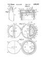
- FIG. 3 is a top plan view showing the closure of FIG. 2 with the cover thereof in its open position;
- FIG. 6 is a top plan view of the tamper evident seal and its hingedly attached manipulating handle
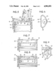
- FIG. 7 is a vertical sectional detail view taken substantially along the line VII--VII in FIG. 3;
- the closure 10 comprises a preferably one-piece molded construction made from a suitable plastic material of any preferred kind adaptable for this purpose. Material of this nature is well known and provides a satisfactory self-sustaining structure with desirable resiliency in those portions of the structure that can benefit therefrom.
- the cover disk 21 has a diameter to seat with a generally rabbet groove 22 in the upper edge of the lip structure 20 and an integral resilient hinge 23 connects the cover to the lip structure 20.
- reinforcing ribs 31 integral with this panel and the partition 25 may be provided.
- latch ribs 32 For retaining the cover 21 on its seat in the closed position, it may be provided with projecting limited length latch ribs 32 on its edge remote from the hinge 23. These ribs 32 releasably engage with complementary latching shoulders 33 formed on the wall provided by the lip structure 20 about the seating groove 22.
- New and improved destructably releasable tamper evident seal means 34 is provided for the dispensing opening 28, within a second well 35 on the opposite side of the partition 25 from the wall 24.
- the dispensing opening 28 is formed in the floor provided by the crown panel 19 in the bottom of the well 35.
- the seal means 34 comprises a seal disk or stopper element 37 which is initially integrally connected to one piece with the panel 19 by means of line of weakening 38 extending entirely about the diameter of the stopper 37.
- the post 41 is of substantial thickness or mass so as to provide a virtually fail-safe connection with the stopper 37 so that the fracturable or rupturable integral thinning connection 38 of the stopper 37 to the crown panel 19 about the edge of the dispensing opening 28 can be of sufficient strength to curtail casual displacement force applied to the stopper stopper 37, but permit fracture and removal displacement of the stopper when adequate tearaway leverage force is applied by an outward pull exerted by means of the handle 40 on the post 41.
- the port 41 may be pointed as shown at 41a of FIG. 6 with the point at the score line or connection 38. In this manner, lifting the portion 45 of the handle 39 will cause the point to break the score line. To facilitate manufacturing the point may be radiused.
- the handle 40 is of out-of-round ring shape comprising an arcuate base bar 42 integrally attached to the post 41 at a secure but somewhat reduced mass, resilient neck 43.
- the bar 42 is of substantially parallel arcuate shape to the adjacent arcuate wall defining the wall 35 and desirably extends symmetrically from opposite sides of the post 41.
- the arcuate bar 42 joins, by means of arcuate connections 44, a substantially straight digitally engageable pull bar 45 extending in parallel adjacency to the partition 25 in the at rest position of the handle 40 wherein it lies in a plane generally parallel to the crown panel 19.
- the top surface of the handle lies freely under the closed cover 21.
- the bearing surface of the rib 49 is desirably formed curvate in cross section as noted at 50.
- the rib 49 engages the wall surface with a resilient thrust enhanced by an at least slightly resiliently flexible integral connection of the rib with the cover panel 21 at a connection neck thinning 51.
- dispensing may be effected through the opening 28.
- Contents remaining in the associated container 12 after a partial dispensing thereof can be protected by reclosing the cover 21.
- the reinforcing rib 49 snuggly fully engaging the surrounding wall surface defining the well 35 in the closed position of the cover 21, an efficient seal against unintentional spilling of container contents through the opened opening 28 and the well 35 is provided.
Abstract
Description
Claims (14)
Priority Applications (1)
| Application Number | Priority Date | Filing Date | Title |
|---|---|---|---|
| US07/222,936 US4901892A (en) | 1988-07-22 | 1988-07-22 | Tamper evident container closure |
Applications Claiming Priority (1)
| Application Number | Priority Date | Filing Date | Title |
|---|---|---|---|
| US07/222,936 US4901892A (en) | 1988-07-22 | 1988-07-22 | Tamper evident container closure |
Publications (1)
| Publication Number | Publication Date |
|---|---|
| US4901892A true US4901892A (en) | 1990-02-20 |
Family
ID=22834339
Family Applications (1)
| Application Number | Title | Priority Date | Filing Date |
|---|---|---|---|
| US07/222,936 Expired - Fee Related US4901892A (en) | 1988-07-22 | 1988-07-22 | Tamper evident container closure |
Country Status (1)
| Country | Link |
|---|---|
| US (1) | US4901892A (en) |
Cited By (32)
| Publication number | Priority date | Publication date | Assignee | Title |
|---|---|---|---|---|
| US5069367A (en) * | 1989-07-12 | 1991-12-03 | Societe Nouvelle De Bouchons Plastiques | Pouring stopper with tear-off guarantee strip with a separate diaphragm |
| US5213235A (en) * | 1991-08-22 | 1993-05-25 | Bunzl Plastics, Inc. | Monoblock plastic tube |
| US5228603A (en) * | 1990-09-04 | 1993-07-20 | Pham Ninh G | Fluid flow control device for a container and container therewith |
| US5273177A (en) * | 1992-07-20 | 1993-12-28 | Campbell Phillip J | Press-to-open dispensing closure |
| US5377882A (en) * | 1990-09-04 | 1995-01-03 | Pham; Ninh G. | Container and closure |
| DE4409946A1 (en) * | 1994-03-23 | 1995-09-28 | Pkl Verpackungssysteme Gmbh | Cuboid flat gable composite packaging and method for its production |
| US5462183A (en) * | 1994-02-07 | 1995-10-31 | Aptargroup, Inc. | Closure with a tamper-evident element |
| US5467879A (en) * | 1993-12-01 | 1995-11-21 | Moore; David N. | Linerless closure and fitment assembly |
| GB2297081A (en) * | 1995-01-19 | 1996-07-24 | Zhongfu Plastic Bottle Co Ltd | Plastic dispensing lid for a drinkable water jar |
| US5579947A (en) * | 1996-01-29 | 1996-12-03 | Zag Ltd. | Organizer latch mechanism |
| US5597096A (en) * | 1996-02-15 | 1997-01-28 | Dart Industries Inc. | Shaker for condiments |
| US5735438A (en) * | 1996-04-26 | 1998-04-07 | Ostrowsky; Efrem | Press-to-open dispensing closure |
| US5797523A (en) * | 1997-02-06 | 1998-08-25 | Aptargroup, Inc. | Snap-action closure with disengaged compression member when lid is closed |
| US5829610A (en) * | 1996-09-13 | 1998-11-03 | Aptargroup, Inc. | Closure with a tamper-indicating element optionally suitable for use as a tool |
| US20030159965A1 (en) * | 2002-02-26 | 2003-08-28 | Mars, Incorporated | Dispenser having one touch flip top opening |
| FR2836899A1 (en) * | 2002-07-05 | 2003-09-12 | Tetra Laval Holding Et Finance | Cap for drinks can has spout which is offset with respect to can outlet but connected to it by a common channel |
| US6732873B2 (en) | 2001-03-09 | 2004-05-11 | J.L. Clark, Inc. | Container lid |
| US20050006387A1 (en) * | 2003-07-07 | 2005-01-13 | Jackson Bruce D. | Reclosable dispenser |
| EP1535854A1 (en) * | 2003-09-26 | 2005-06-01 | Invat S.r.l. | Cap for containers with cover lid rotating on a transverse horizontal axis snap activated by pushing with a finger or thumb |
| US20060016836A1 (en) * | 2004-07-20 | 2006-01-26 | Rick Gaiser | Shaped spouts for flip-top closures |
| WO2008024774A2 (en) * | 2006-08-21 | 2008-02-28 | Tropicana Products, Inc. | Container having improved pouring characteristics |
| US20080078775A1 (en) * | 2006-08-21 | 2008-04-03 | Tropicana Products, Inc. | Closure For Container |
| US20080308569A1 (en) * | 2007-06-13 | 2008-12-18 | J.L Clark, Inc. | Push and Flip Container |
| US20090114562A1 (en) * | 2007-11-02 | 2009-05-07 | Walgreen Co. | Multiple compartment container |
| US20110095023A1 (en) * | 2008-05-30 | 2011-04-28 | Hiroshi Yoshihara | Integrally formed attachment cap with lid opened by single push |
| US20120160881A1 (en) * | 2009-03-02 | 2012-06-28 | Wm. Wrigley Jr. Company | Dispensable product container |
| US20120168329A1 (en) * | 2009-06-29 | 2012-07-05 | Adam Berggren | Container for Snus |
| US20150122817A1 (en) * | 2012-05-04 | 2015-05-07 | Crown Packaging Technology, Inc. | Container with an insert and a lid |
| US20160122094A1 (en) * | 2014-10-30 | 2016-05-05 | Getac Technology Corporation | Single piece water resistance door |
| US10390561B2 (en) | 2015-06-16 | 2019-08-27 | Fiedler & Lundgren Ab | Container |
| US10464724B2 (en) | 2015-06-16 | 2019-11-05 | Fiedler & Lundgren Ab | Container |
| US11352178B2 (en) * | 2018-01-26 | 2022-06-07 | Aptargroup, Inc. | Closure for a container |
Citations (7)
| Publication number | Priority date | Publication date | Assignee | Title |
|---|---|---|---|---|
| US3434620A (en) * | 1966-03-10 | 1969-03-25 | American Flange & Mfg | Frangible plastic closure |
| US3850350A (en) * | 1973-12-06 | 1974-11-26 | Safety Packaging Corp | Shaker cap |
| US3881639A (en) * | 1973-12-05 | 1975-05-06 | Weatherchem Corp | Safety closure for containers |
| US4607768A (en) * | 1984-07-23 | 1986-08-26 | Continental White Cap, Inc. | Dispensing closure with latch mechanism |
| US4699290A (en) * | 1986-06-18 | 1987-10-13 | Adams Jay J | Sanitary tamperproof double closure container end cap |
| US4724978A (en) * | 1987-05-05 | 1988-02-16 | Acorn Technology Inc. | Plastic container with integral tamper-evident, reclosable lid |
| US4760931A (en) * | 1986-12-22 | 1988-08-02 | Sunbeam Plastics Corporation | Safety container neck insert |
-
1988
- 1988-07-22 US US07/222,936 patent/US4901892A/en not_active Expired - Fee Related
Patent Citations (7)
| Publication number | Priority date | Publication date | Assignee | Title |
|---|---|---|---|---|
| US3434620A (en) * | 1966-03-10 | 1969-03-25 | American Flange & Mfg | Frangible plastic closure |
| US3881639A (en) * | 1973-12-05 | 1975-05-06 | Weatherchem Corp | Safety closure for containers |
| US3850350A (en) * | 1973-12-06 | 1974-11-26 | Safety Packaging Corp | Shaker cap |
| US4607768A (en) * | 1984-07-23 | 1986-08-26 | Continental White Cap, Inc. | Dispensing closure with latch mechanism |
| US4699290A (en) * | 1986-06-18 | 1987-10-13 | Adams Jay J | Sanitary tamperproof double closure container end cap |
| US4760931A (en) * | 1986-12-22 | 1988-08-02 | Sunbeam Plastics Corporation | Safety container neck insert |
| US4724978A (en) * | 1987-05-05 | 1988-02-16 | Acorn Technology Inc. | Plastic container with integral tamper-evident, reclosable lid |
Cited By (51)
| Publication number | Priority date | Publication date | Assignee | Title |
|---|---|---|---|---|
| US5069367A (en) * | 1989-07-12 | 1991-12-03 | Societe Nouvelle De Bouchons Plastiques | Pouring stopper with tear-off guarantee strip with a separate diaphragm |
| US5228603A (en) * | 1990-09-04 | 1993-07-20 | Pham Ninh G | Fluid flow control device for a container and container therewith |
| US5377882A (en) * | 1990-09-04 | 1995-01-03 | Pham; Ninh G. | Container and closure |
| US5213235A (en) * | 1991-08-22 | 1993-05-25 | Bunzl Plastics, Inc. | Monoblock plastic tube |
| US5273177A (en) * | 1992-07-20 | 1993-12-28 | Campbell Phillip J | Press-to-open dispensing closure |
| US5467879A (en) * | 1993-12-01 | 1995-11-21 | Moore; David N. | Linerless closure and fitment assembly |
| US5462183A (en) * | 1994-02-07 | 1995-10-31 | Aptargroup, Inc. | Closure with a tamper-evident element |
| US5875958A (en) * | 1994-03-23 | 1999-03-02 | Pkl Verpackungssysteme Gmbh | Cuboid flat gable composite package and a process for its production |
| DE4409946A1 (en) * | 1994-03-23 | 1995-09-28 | Pkl Verpackungssysteme Gmbh | Cuboid flat gable composite packaging and method for its production |
| GB2297081A (en) * | 1995-01-19 | 1996-07-24 | Zhongfu Plastic Bottle Co Ltd | Plastic dispensing lid for a drinkable water jar |
| US5579947A (en) * | 1996-01-29 | 1996-12-03 | Zag Ltd. | Organizer latch mechanism |
| US5597096A (en) * | 1996-02-15 | 1997-01-28 | Dart Industries Inc. | Shaker for condiments |
| US5735438A (en) * | 1996-04-26 | 1998-04-07 | Ostrowsky; Efrem | Press-to-open dispensing closure |
| US5829610A (en) * | 1996-09-13 | 1998-11-03 | Aptargroup, Inc. | Closure with a tamper-indicating element optionally suitable for use as a tool |
| US5797523A (en) * | 1997-02-06 | 1998-08-25 | Aptargroup, Inc. | Snap-action closure with disengaged compression member when lid is closed |
| US6732873B2 (en) | 2001-03-09 | 2004-05-11 | J.L. Clark, Inc. | Container lid |
| US6742666B1 (en) | 2001-03-09 | 2004-06-01 | J.L. Clark, Inc. | Container lid with flip door |
| US20030159965A1 (en) * | 2002-02-26 | 2003-08-28 | Mars, Incorporated | Dispenser having one touch flip top opening |
| US6763945B2 (en) * | 2002-02-26 | 2004-07-20 | Mars, Incorporated | Dispenser having one touch flip top opening |
| FR2836899A1 (en) * | 2002-07-05 | 2003-09-12 | Tetra Laval Holding Et Finance | Cap for drinks can has spout which is offset with respect to can outlet but connected to it by a common channel |
| US20050006387A1 (en) * | 2003-07-07 | 2005-01-13 | Jackson Bruce D. | Reclosable dispenser |
| US8950630B2 (en) * | 2003-07-07 | 2015-02-10 | Bruce D. Jackson | Reclosable dispenser |
| EP1535854A1 (en) * | 2003-09-26 | 2005-06-01 | Invat S.r.l. | Cap for containers with cover lid rotating on a transverse horizontal axis snap activated by pushing with a finger or thumb |
| US20060016836A1 (en) * | 2004-07-20 | 2006-01-26 | Rick Gaiser | Shaped spouts for flip-top closures |
| US20080078775A1 (en) * | 2006-08-21 | 2008-04-03 | Tropicana Products, Inc. | Closure For Container |
| US20080078765A1 (en) * | 2006-08-21 | 2008-04-03 | Tropicana Products, Inc. | Container Having Improved Pouring Characteristics |
| WO2008024774A3 (en) * | 2006-08-21 | 2008-04-10 | Tropicana Prod Inc | Container having improved pouring characteristics |
| US8113374B2 (en) | 2006-08-21 | 2012-02-14 | Tropicana Products, Inc. | Closure for container having removable portion and sealing membrane |
| WO2008024774A2 (en) * | 2006-08-21 | 2008-02-28 | Tropicana Products, Inc. | Container having improved pouring characteristics |
| US8678215B2 (en) | 2006-08-21 | 2014-03-25 | Tropicana Products, Inc. | Container having improved pouring characteristics |
| US20080308569A1 (en) * | 2007-06-13 | 2008-12-18 | J.L Clark, Inc. | Push and Flip Container |
| US7954664B2 (en) * | 2007-06-13 | 2011-06-07 | J.L. Clark, Inc. | Push and flip container |
| US20110204073A1 (en) * | 2007-06-13 | 2011-08-25 | J.L. Clark, Inc. | Push and Flip Container |
| US8579152B2 (en) | 2007-06-13 | 2013-11-12 | J.L. Clark, Inc. | Push and flip container |
| US20090114562A1 (en) * | 2007-11-02 | 2009-05-07 | Walgreen Co. | Multiple compartment container |
| US7624890B2 (en) | 2007-11-02 | 2009-12-01 | Walgreen Co. | Multiple compartment container |
| US20110095023A1 (en) * | 2008-05-30 | 2011-04-28 | Hiroshi Yoshihara | Integrally formed attachment cap with lid opened by single push |
| US8672196B2 (en) * | 2009-03-02 | 2014-03-18 | Wm. Wrigley Jr. Company | Dispensable product container |
| US20120160881A1 (en) * | 2009-03-02 | 2012-06-28 | Wm. Wrigley Jr. Company | Dispensable product container |
| US20120168329A1 (en) * | 2009-06-29 | 2012-07-05 | Adam Berggren | Container for Snus |
| US8869980B2 (en) * | 2009-06-29 | 2014-10-28 | Fielder & Lundgren AB | Container for snus |
| US20150122817A1 (en) * | 2012-05-04 | 2015-05-07 | Crown Packaging Technology, Inc. | Container with an insert and a lid |
| CN105636377B (en) * | 2014-10-30 | 2019-03-01 | 神讯电脑(昆山)有限公司 | Single-piece water door |
| CN105636377A (en) * | 2014-10-30 | 2016-06-01 | 神讯电脑(昆山)有限公司 | Single-piece waterproof door |
| US20160122094A1 (en) * | 2014-10-30 | 2016-05-05 | Getac Technology Corporation | Single piece water resistance door |
| US10310569B2 (en) * | 2014-10-30 | 2019-06-04 | Getac Technology Corporation | Single piece water resistance door |
| US10390561B2 (en) | 2015-06-16 | 2019-08-27 | Fiedler & Lundgren Ab | Container |
| US10464724B2 (en) | 2015-06-16 | 2019-11-05 | Fiedler & Lundgren Ab | Container |
| US10874138B2 (en) | 2015-06-16 | 2020-12-29 | Fiedler & Lundgren Ab | Container |
| US11046487B2 (en) | 2015-06-16 | 2021-06-29 | Fiedler & Lundgren Ab | Container with flexible separating wall |
| US11352178B2 (en) * | 2018-01-26 | 2022-06-07 | Aptargroup, Inc. | Closure for a container |
Similar Documents
| Publication | Publication Date | Title |
|---|---|---|
| US4901892A (en) | Tamper evident container closure | |
| US4397400A (en) | Nondetachable resealable closure | |
| US3624789A (en) | Container stacking and sealing overcap | |
| US4453646A (en) | Closure having frangible means | |
| US3952911A (en) | Non-detachable and reclosable easy opening container closure structure | |
| US4407423A (en) | Detachable resealable closure | |
| US4919286A (en) | Hinged closure and container | |
| US4807769A (en) | Tamper indicating closure | |
| US3927805A (en) | Tilt/lift safety closure | |
| US4984716A (en) | Two piece tamper evident hinged closure cap | |
| US3495746A (en) | Plastic closures for containers and combinations | |
| US3494500A (en) | Tear-type plastic closure with plastic pull ring | |
| US4895282A (en) | Dispensing closure with pull tab for enlarging orifice | |
| JPS63138962A (en) | Vessel sealing device | |
| KR920008337B1 (en) | Container with pressure-release lid | |
| JPS6251825B2 (en) | ||
| US4440310A (en) | Closure for domed beverage containers and the like | |
| US3073472A (en) | Closure for containers | |
| US5622273A (en) | Resealable snap-fit plastic closure | |
| JPS6294557A (en) | Vessel and cover for vessel | |
| US20110168661A1 (en) | Flip cap | |
| US4149651A (en) | Closure device | |
| US4328906A (en) | Container and closure therefor | |
| WO2005108231A1 (en) | Hinged overcap for rectangular containers | |
| US3272382A (en) | Easy opening container |
Legal Events
| Date | Code | Title | Description |
|---|---|---|---|
| AS | Assignment |
Owner name: MAGENTA CORPORATION, 3800 N. MILWAUKEE, CHICAGO, I Free format text: ASSIGNMENT OF ASSIGNORS INTEREST.;ASSIGNOR:SONG, JOHN S.;REEL/FRAME:004933/0795 Effective date: 19880720 |
|
| FEPP | Fee payment procedure |
Free format text: PAYOR NUMBER ASSIGNED (ORIGINAL EVENT CODE: ASPN); ENTITY STATUS OF PATENT OWNER: SMALL ENTITY |
|
| FPAY | Fee payment |
Year of fee payment: 4 |
|
| FPAY | Fee payment |
Year of fee payment: 8 |
|
| REMI | Maintenance fee reminder mailed | ||
| LAPS | Lapse for failure to pay maintenance fees | ||
| STCH | Information on status: patent discontinuation |
Free format text: PATENT EXPIRED DUE TO NONPAYMENT OF MAINTENANCE FEES UNDER 37 CFR 1.362 |
|
| FP | Lapsed due to failure to pay maintenance fee |
Effective date: 20020220 |
|
| AS | Assignment |
Owner name: MAGENTA LLC (F/K/A SFH-MAGENTA LLC), ILLINOIS Free format text: ASSIGNMENT OF ASSIGNORS INTEREST;ASSIGNOR:MAGENTA CORPORATION;REEL/FRAME:021172/0124 Effective date: 20080605 |
|
| AS | Assignment |
Owner name: HARRIS N.A., ILLINOIS Free format text: SECURITY AGREEMENT;ASSIGNOR:SFH-MAGENTA LLC, TO BE RENAMED MAGENTA, LLC;REEL/FRAME:021172/0823 Effective date: 20080605 |