US4901938A - Electrical cord retractor - Google Patents
Electrical cord retractor Download PDFInfo
- Publication number
- US4901938A US4901938A US07/274,465 US27446588A US4901938A US 4901938 A US4901938 A US 4901938A US 27446588 A US27446588 A US 27446588A US 4901938 A US4901938 A US 4901938A
- Authority
- US
- United States
- Prior art keywords
- case
- electrical cord
- spool
- cord
- retractor
- Prior art date
- Legal status (The legal status is an assumption and is not a legal conclusion. Google has not performed a legal analysis and makes no representation as to the accuracy of the status listed.)
- Expired - Fee Related
Links
Images
Classifications
-
- B—PERFORMING OPERATIONS; TRANSPORTING
- B65—CONVEYING; PACKING; STORING; HANDLING THIN OR FILAMENTARY MATERIAL
- B65H—HANDLING THIN OR FILAMENTARY MATERIAL, e.g. SHEETS, WEBS, CABLES
- B65H75/00—Storing webs, tapes, or filamentary material, e.g. on reels
- B65H75/02—Cores, formers, supports, or holders for coiled, wound, or folded material, e.g. reels, spindles, bobbins, cop tubes, cans, mandrels or chucks
- B65H75/34—Cores, formers, supports, or holders for coiled, wound, or folded material, e.g. reels, spindles, bobbins, cop tubes, cans, mandrels or chucks specially adapted or mounted for storing and repeatedly paying-out and re-storing lengths of material provided for particular purposes, e.g. anchored hoses, power cables
- B65H75/38—Cores, formers, supports, or holders for coiled, wound, or folded material, e.g. reels, spindles, bobbins, cop tubes, cans, mandrels or chucks specially adapted or mounted for storing and repeatedly paying-out and re-storing lengths of material provided for particular purposes, e.g. anchored hoses, power cables involving the use of a core or former internal to, and supporting, a stored package of material
- B65H75/44—Constructional details
-
- B—PERFORMING OPERATIONS; TRANSPORTING
- B65—CONVEYING; PACKING; STORING; HANDLING THIN OR FILAMENTARY MATERIAL
- B65H—HANDLING THIN OR FILAMENTARY MATERIAL, e.g. SHEETS, WEBS, CABLES
- B65H2701/00—Handled material; Storage means
- B65H2701/30—Handled filamentary material
- B65H2701/39—Other types of filamentary materials or special applications
- B65H2701/3919—USB, earphones, audio or video cables, e.g. for connecting small electronic devices such as MP3 players or mobile telephones
Definitions
- This invention relates to electrical cord retractors which wind-up and store electrical cords when they are not in use.
- the invention also relates to storage of an excess portion of the length of an electrical cord which is in use.
- Electrical cords provided with many types of electrical appliances and apparatus are often longer than required in the particular environment in which the appliance or apparatus is used.
- the cord extending from the headset, or earphones, to the plug which connects to the radio is usually longer than needed.
- the excess length of the cord hangs down when the radio is in use, and is liable to get caught on objects which the user passes.
- the cord when use of the radio is discontinued, the cord must be gathered together and placed in a pocket or purse, which if done hurriedly leaves a tangle of cord subject to becoming knotted.
- the electrical cord and retractor are furnished together as a unit. They offer no way to assemble a pre-existing cord with the retractor.
- an object of the present invention to provide an electrical cord retractor useful with an existing electrical cord which forms part of an electrical appliance or apparatus already in the possession of the user.
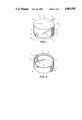
- FIG. 1 is a perspective view of an electrical cord retractor in accordance with the present invention
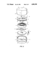
- FIG. 2 is an exploded perspective view showing the various parts of the retractor
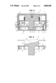
- FIG. 3 is a diametrical cross-sectional view taken along line 3--3 of FIG. 1;
- FIG. 4 is a diametrical cross-sectional view through the winder or spool, taken in a plane perpendicular to the plane of FIG. 3;
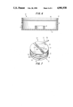
- FIG. 5 is a perspective view of the cover portion of the retractor case, the cover being upside down;
- FIG. 6 is a diametrical cross-sectional view through the base portion of the retractor case.
- FIG. 7 is a perspective view of the retractor with the cover portion of the case removed.
- the electrical cord retractor chosen to illustrate the present invention includes a case having a base portion 10 and a cover portion 11.
- Base 10 is a cup-like element (FIGS. 2, 3 and 6) having a flat bottom wall 12 and a cylindrical side wall 13 extending upwardly from the periphery of the bottom wall.
- Projecting upwardly from the center of bottom wall 12 is a short tubular boss 14 which serves as a bearing for the retractor winder or spool.
- Formed in the outer surface of sidewall 13 is an annular groove 15, and formed in the inner surface of sidewall 13 is another annular groove 16.
- a hole 17 extends completely through the thickness of sidewall 13.
- Cover 11 is also a cup-like element (FIGS. 1-3) having a flat top wall 20 and generally cylindrical sidewall 21 extending downwardly from the periphery of the top wall.
- the inner surface of sidewall 21 presents a generally annular ridge 22 adapted to be accommodated by annular groove 15 in sidewall 13 of base 10.
- base 10 and cover 11 are preferably made of molded plastic or thin metal so that they have sufficient resilience to allow for interconnection and release of ridge 22 and groove 15.
- Sidewall 21 of cover 11 is discontinuous at two diametrically opposite points, and at those points the vertical edges 23 presented by the two semi-circular parts of sidewall 21 are out of alignment so as to define two vertical passageways or slots 24.
- Each slot 24 extends to, and is open at, the free edge 25 of sidewall 21.
- Slot 24 could alternately be located in sidewall 13 of base 10.
- the sidewall is also formed with a generally semi-circular notch 26 which extends to free edge 25 of the sidewall.
- a winding means which in the present example is in the form of a spool 29 (FIGS. 2,3,4, and 7).
- the spool comprises a generally cylindrical hub 30 having radially-extending upper and lower flanges 31 and 32 at its upper and lower ends, respectively, Extending axially downwardly from the center of lower flange 32 is a shaft 33, the lower end of which is rotatably accommodated within boss 14 of the base portion 10 of the case. At one side, shaft 33 is formed with a longitudinal keyway 34 (FIG. 3).
- a discontinuous circular wall defining a series of arcuate springy fingers 37.
- Projecting outwardly from each finger 37 is an arcuate ridge 38 adapted to be slidably accommodated within groove 16 formed in the inner surface of sidewall 13 of base 10.
- Spool 29 may be formed of molded plastic or other suitable material, so that when the spool is assembled with base 10, fingers 37 and sidewall 13 have sufficient resilience to permit ridges 38 to snap into groove 16. The cooperation between ridges 38 and groove 16 serves to interconnect spool 29 with base 10, and also insures stable rotation of spool 29 within the case.
- Spool 29 is formed with an electrical cord guide, in this example the guide being a slot 39 extending from the outer face of flange 31 into the spool hub 30.
- the base 40 of slot 39 lies at an acute angle to the planes containing flanges 31 and 32.
- the angled nature of slot base 40 encourages more even winding of an electrical cord around hub 30 of spool 29.
- portion 41b will be wound nearer the top of hub 30 and portion 41c of the cord will be wound closer to the bottom of hub 30, as a result of which the cord will be evenly wound along the entire length of hub 30.
- base 40 of slot 39 were parallel to flanges 31 and 32, upon rotation of spool 29, electrical cord 41 would build up in the plane of base 40 resulting in an uneven distribution of the cord along the length of hub 30.
- a spiral spring 44 (FIG. 2) surrounds shaft 33 directly beneath lower flange 32. (For clarity, the spring has been omitted from FIG. 3.)
- the inner end 45 of the spring is fixed to shaft 33, such as by a pin 46.
- the outer end 47 of spring 44 is fixed to sidewall 13 of base 10, such as by a pin 48.
- spring 44 will be tensioned, so that when released the spring will automatically rotate spool 29 in a clockwise direction.
- Located directly above boss 14 is a toothed wheel 51 having a series of teeth around its periphery separated by indentations 52. Wheel 51 has a central hole 53 through which shaft 33 of spool 29 passes.
- a key 54 (FIGS. 2 and 3) projects into hole 53, and engages keyway 34 in shaft 33. As a result of the interengagement between key 54 and keyway 34, toothed wheel 51 and pulley 29 rotate together.
- a detent 57 (FIGS. 2 and 3), which may be formed of a strip of springy metal, is fixed at one of its ends to the inner surface of base 10, conveniently by pin 48 which also anchors the outer end of spring 44. Intermediate its ends detent 57 presents a bulge 58 adapted to engage indentations 52 in toothed wheel 51. When bulge 58 of detent 57 engages in one of the indentations 52 of wheel 51, the detent prevents rotation of spool 29 under the influence of spring 44.
- actuator 59 Directly above wheel 51 is an elongated actuator 59 (FIGS. 2 and 3). Between its ends, actuator 59 is provided with an eliptical opening 60 through which shaft 33 of spool 29 passes. The length of opening 60 is larger than the diameter of shaft 33, so that actuator 59 is permitted to slide longitudinally with respect to shaft 33 and case 10, 11. One end 61 of actuator 59 is located adjacent to bulge 58 of detent 57. The other end of actuator 59 extends through hole 17 in sidewall 13 of base 10 (FIG. 3), and carries a push button 62 slidably accommodated within notch 26 in sidewall 21 of cover 11 (FIGS. 1-3 and 7).
- the case is opened by removing cover 11 from base 10, thereby exposing spool 29.
- the spool is rotated counterclockwise in FIG. 2 in order to tighten and thereby tension spring 44.
- the spring has been tightened to its maximum degree, the spool may be released and it will be latched in that position by cooperation of detent 57 and toothed wheel 51.
- the middle portion 41a (FIG. 7) of an electrical cord 41 is then laid into slot 39.
- Cover 11 may then be replaced on base 10, this action being permitted by the fact that slots 24 in sidewall 21 of cover 11 are open at the free edge 25 of the sidewall.
- the slots can be slipped over electrical cord portions 41b and 41c, respectively, so as to introduce those cord portions into the slots.
- the entire length of cord 41 can be wound on spool 29, leaving only the ear phones and plug exposed outside case 10, 11.
- the plug is inserted into the radio, and just enough cord is unwound from the retractor to provide the length needed for the cord to reach from the radio to the user's ears. In this way, no excess cord will hang down and be subject to snagging or tangling.
- the retractor is used with a piece of apparatus having an electrical cord plugged into the wall outlet
- the retractor is applied to a point of the electrical cord between its ends, and activated to wind all excess cord within the retractor. In this way, only the length of cord needed to reach from the apparatus to the outlet is exposed.
- the retractor is used to retract the entire length of apparatus cord, thereby completely storing the cord during the move.
- the retractor case could be provided with a mounting means, most conveniently attached to the outer surface of bottom wall 12 of base 10.
- the mounting means could be a clip for attachment to the user's belt, or it could be a magnet or a hook and loop type fastener such as that sold under the trademark Velcro for attaching the retractor to the appliance or apparatus with which the retractor is used.
Abstract
An electrical cord retractor includes a closed hollow case separate from any apparatus with which an electrical cord will be used. Within the case is a winder, such as a rotatable spool, and the case is openable to permit an electrical cord to be wound upon the spool. The case wall has passageways through which an electrical cord can pass from the spool within the case to the exterior of the case, so that the cord can be connected to an apparatus independent of the case. The passageway may be slots which extend to a free edge of the case wall, so that after an electrical cord is wound on the spool, portions of the electrical cord extending from the spool can be inserted into the slots as the case is closed. The spool has a cord guide, in the form of a slot, extending from the external face of one of the spool flanges into the spool hub. A portion of an electrical cord is held stationary in the slot so that as the spool is rotated the remainder of the cord is wound upon the spool. The slot in the spool is arranged at an acute angle to the planes of the spool flanges, so that as the spool is rotated, the two portions of the cord extending from the slot will be wound on different sections of the spool hub. Within the case is a spring, constantly urging the spool to rotate in one direction, and a latch for releasably locking the spool against rotation.
Description
This invention relates to electrical cord retractors which wind-up and store electrical cords when they are not in use. The invention also relates to storage of an excess portion of the length of an electrical cord which is in use.
Electrical cords provided with many types of electrical appliances and apparatus are often longer than required in the particular environment in which the appliance or apparatus is used. For example, in the case of small, carry-about portable radios, the cord extending from the headset, or earphones, to the plug which connects to the radio, is usually longer than needed. As a result, the excess length of the cord hangs down when the radio is in use, and is liable to get caught on objects which the user passes. Also, when use of the radio is discontinued, the cord must be gathered together and placed in a pocket or purse, which if done hurriedly leaves a tangle of cord subject to becoming knotted.
Other examples of the problem are electrical lamp and appliance cords, which if too long sit in a jumbled mess on the floor between the lamp or appliance and the electrical outlet into which the cord is plugged. The problem is not limited to households, but also is found in laboratories and studios, where excess length of electrical cords are found heaped on the floor near electrical apparatus of all kinds.
Electrical cord retractors are known which are built into the pieces of apparatus with which they are used. Examples of such retractors are shown in U.S. Pat. Nos. 2,856,517 and 2,591,438. Independent cord retractors pre-assembled with lengths of electrical cord are also known, as indicated by U.S. Pat. Nos. 3,984,645 and 3,426,282.
In all these cases, the electrical cord and retractor are furnished together as a unit. They offer no way to assemble a pre-existing cord with the retractor.
It is, therefore, an object of the present invention to provide an electrical cord retractor useful with an existing electrical cord which forms part of an electrical appliance or apparatus already in the possession of the user.
It is another object of the invention to provide such a retractor capable of being opened, so that an electric cord forming part of an existing appliance or apparatus can be wound into the retractor, after which the retractor can be reclosed.
It is a further object of the invention to provide such a retractor incorporating a winder, capable of winding and storing an electrical cord when the latter is not in use, or of winding and storing an excess length of an electrical cord while the latter is in use.
Additional objects and features of the present invention will be apparent from the following description, in which reference is made to the accompanying drawings.
In the drawings:
FIG. 1 is a perspective view of an electrical cord retractor in accordance with the present invention;
FIG. 2 is an exploded perspective view showing the various parts of the retractor;
FIG. 3 is a diametrical cross-sectional view taken along line 3--3 of FIG. 1;
FIG. 4 is a diametrical cross-sectional view through the winder or spool, taken in a plane perpendicular to the plane of FIG. 3;
FIG. 5 is a perspective view of the cover portion of the retractor case, the cover being upside down;
FIG. 6 is a diametrical cross-sectional view through the base portion of the retractor case; and
FIG. 7 is a perspective view of the retractor with the cover portion of the case removed.
The electrical cord retractor chosen to illustrate the present invention includes a case having a base portion 10 and a cover portion 11. Base 10 is a cup-like element (FIGS. 2, 3 and 6) having a flat bottom wall 12 and a cylindrical side wall 13 extending upwardly from the periphery of the bottom wall. Projecting upwardly from the center of bottom wall 12 is a short tubular boss 14 which serves as a bearing for the retractor winder or spool. Formed in the outer surface of sidewall 13 is an annular groove 15, and formed in the inner surface of sidewall 13 is another annular groove 16. A hole 17 extends completely through the thickness of sidewall 13.
Cover 11 is also a cup-like element (FIGS. 1-3) having a flat top wall 20 and generally cylindrical sidewall 21 extending downwardly from the periphery of the top wall. The inner surface of sidewall 21 presents a generally annular ridge 22 adapted to be accommodated by annular groove 15 in sidewall 13 of base 10. Thus, when cover 11 is closed over base 10 (FIG. 3), ridge 22 snaps into groove 15 to releasably hold the base and cover together so as to close the case. Base 10 and cover 11 are preferably made of molded plastic or thin metal so that they have sufficient resilience to allow for interconnection and release of ridge 22 and groove 15.
Sidewall 21 of cover 11 is discontinuous at two diametrically opposite points, and at those points the vertical edges 23 presented by the two semi-circular parts of sidewall 21 are out of alignment so as to define two vertical passageways or slots 24. Each slot 24 extends to, and is open at, the free edge 25 of sidewall 21. Slot 24 could alternately be located in sidewall 13 of base 10. The sidewall is also formed with a generally semi-circular notch 26 which extends to free edge 25 of the sidewall.
Within case 10,11 is a winding means, which in the present example is in the form of a spool 29 (FIGS. 2,3,4, and 7). The spool comprises a generally cylindrical hub 30 having radially-extending upper and lower flanges 31 and 32 at its upper and lower ends, respectively, Extending axially downwardly from the center of lower flange 32 is a shaft 33, the lower end of which is rotatably accommodated within boss 14 of the base portion 10 of the case. At one side, shaft 33 is formed with a longitudinal keyway 34 (FIG. 3).
Depending from lower flange 32 is a discontinuous circular wall defining a series of arcuate springy fingers 37. Projecting outwardly from each finger 37 is an arcuate ridge 38 adapted to be slidably accommodated within groove 16 formed in the inner surface of sidewall 13 of base 10. Spool 29 may be formed of molded plastic or other suitable material, so that when the spool is assembled with base 10, fingers 37 and sidewall 13 have sufficient resilience to permit ridges 38 to snap into groove 16. The cooperation between ridges 38 and groove 16 serves to interconnect spool 29 with base 10, and also insures stable rotation of spool 29 within the case.
Spool 29 is formed with an electrical cord guide, in this example the guide being a slot 39 extending from the outer face of flange 31 into the spool hub 30. As best shown in FIG. 4, the base 40 of slot 39 lies at an acute angle to the planes containing flanges 31 and 32. The angled nature of slot base 40 encourages more even winding of an electrical cord around hub 30 of spool 29. When a portion 41a (FIG. 7) of an electrical cord 41 is laid into slot 39, portion 41b of the cord will be closer to flange 31 and portion 41c of the cord will be closer to flange 32, due to the angled nature of slot base 40. Thereafter, as spool 29 is rotated, portion 41b will be wound nearer the top of hub 30 and portion 41c of the cord will be wound closer to the bottom of hub 30, as a result of which the cord will be evenly wound along the entire length of hub 30. In contrast, if base 40 of slot 39 were parallel to flanges 31 and 32, upon rotation of spool 29, electrical cord 41 would build up in the plane of base 40 resulting in an uneven distribution of the cord along the length of hub 30.
A spiral spring 44 (FIG. 2) surrounds shaft 33 directly beneath lower flange 32. (For clarity, the spring has been omitted from FIG. 3.) The inner end 45 of the spring is fixed to shaft 33, such as by a pin 46. The outer end 47 of spring 44 is fixed to sidewall 13 of base 10, such as by a pin 48. It will be appreciated that as spool 29 is rotated in a counter-clockwise direction, in FIG. 2, spring 44 will be tensioned, so that when released the spring will automatically rotate spool 29 in a clockwise direction. Located directly above boss 14 is a toothed wheel 51 having a series of teeth around its periphery separated by indentations 52. Wheel 51 has a central hole 53 through which shaft 33 of spool 29 passes. A key 54 (FIGS. 2 and 3) projects into hole 53, and engages keyway 34 in shaft 33. As a result of the interengagement between key 54 and keyway 34, toothed wheel 51 and pulley 29 rotate together.
A detent 57 (FIGS. 2 and 3), which may be formed of a strip of springy metal, is fixed at one of its ends to the inner surface of base 10, conveniently by pin 48 which also anchors the outer end of spring 44. Intermediate its ends detent 57 presents a bulge 58 adapted to engage indentations 52 in toothed wheel 51. When bulge 58 of detent 57 engages in one of the indentations 52 of wheel 51, the detent prevents rotation of spool 29 under the influence of spring 44.
Directly above wheel 51 is an elongated actuator 59 (FIGS. 2 and 3). Between its ends, actuator 59 is provided with an eliptical opening 60 through which shaft 33 of spool 29 passes. The length of opening 60 is larger than the diameter of shaft 33, so that actuator 59 is permitted to slide longitudinally with respect to shaft 33 and case 10, 11. One end 61 of actuator 59 is located adjacent to bulge 58 of detent 57. The other end of actuator 59 extends through hole 17 in sidewall 13 of base 10 (FIG. 3), and carries a push button 62 slidably accommodated within notch 26 in sidewall 21 of cover 11 (FIGS. 1-3 and 7). When push button 62 is depressed, end 61 of actuator 59 pushes bulge 58 of detent 57 out of engagement with indentations 52, thereby releasing the latching function of detent 57 and wheel 51 so as to free spool 29 for rotation by spring 44. When push button 62 is released, the resilience of detent 57 returns actuator 59 to its initial position and permits bulge 58 to engage one of the indentations 52 to relatch the spool.
In use, the case is opened by removing cover 11 from base 10, thereby exposing spool 29. The spool is rotated counterclockwise in FIG. 2 in order to tighten and thereby tension spring 44. When the spring has been tightened to its maximum degree, the spool may be released and it will be latched in that position by cooperation of detent 57 and toothed wheel 51. The middle portion 41a (FIG. 7) of an electrical cord 41 is then laid into slot 39. Cover 11 may then be replaced on base 10, this action being permitted by the fact that slots 24 in sidewall 21 of cover 11 are open at the free edge 25 of the sidewall. As a result, the slots can be slipped over electrical cord portions 41b and 41c, respectively, so as to introduce those cord portions into the slots. After the case has been closed, push button 62 is depressed to disengage detent 57 and wheel 51, as a result of which spring 44 rotates spool 29 and causes electrical cord 41 to be wound on the spool hub 30 (FIG. 3). If desired, cord 41 could be wound on spool 29, as described above, prior to closing the case, after which cover 11 can be assembled with base 10.
When the retractor is used with an item such as a portable radio headset, the entire length of cord 41 can be wound on spool 29, leaving only the ear phones and plug exposed outside case 10, 11. When the headset is to be used, the plug is inserted into the radio, and just enough cord is unwound from the retractor to provide the length needed for the cord to reach from the radio to the user's ears. In this way, no excess cord will hang down and be subject to snagging or tangling.
Where the retractor is used with a piece of apparatus having an electrical cord plugged into the wall outlet, the retractor is applied to a point of the electrical cord between its ends, and activated to wind all excess cord within the retractor. In this way, only the length of cord needed to reach from the apparatus to the outlet is exposed. When the apparatus is to be moved, it is unplugged from the outlet, and the retractor is used to retract the entire length of apparatus cord, thereby completely storing the cord during the move.
If desired, the retractor case could be provided with a mounting means, most conveniently attached to the outer surface of bottom wall 12 of base 10. The mounting means could be a clip for attachment to the user's belt, or it could be a magnet or a hook and loop type fastener such as that sold under the trademark Velcro for attaching the retractor to the appliance or apparatus with which the retractor is used.
The invention has been shown and described in preferred form only, and by way of example, and many variations may be made in the invention which will still be comprised within its spirit. It is understood, therefore, that the invention is not limited to any specific form or embodiment except insofar as such limitations are included in the appended claims.
Claims (9)
1. An electrical cord retractor for use with an electrical cord already possessed by the user of the retractor, the retractor comprising:
a closed hollow case separate from any apparatus with which an electrical cord may be used, the closed case containing no electrical cord,
winder means within the case rotatable with respect to the case,
a spring within the case for constantly urging rotation of the winder means in one direction with respect to the case,
latch means within the case for preventing rotation of the winder means when the spring is tensioned, the latch means including a toothed wheel rotatable with the winder means, and a detent of springy material adapted to engage the teeth of the wheel to prevent rotation thereof,
manually-operable means for releasing the latch, said means including a single actuator element slidable with respect to the case, one end of the actuator being adjacent to the detent and the other end being exposed on the exterior of the case, the actuator being slidable in a direction transverse to the axis of rotation of the winder for engaging the detent and causing disengagement between the detent and the toothed wheel,
the case including a base and a cover,
means for releasably securing the cover to the base so that the case can be opened at will to permit an electrical cord to be wound upon the winder means, after which the case can be reclosed, and
passageway means in the closed case through which an electrical cord can pass rom the winder means within the case to the exterior of the case for connection to an apparatus independent of the case,
the passageway means being so formed that an electrical cord extending from the winder means can be inserted into the passageway means as the case is closed.
2. An electrical cord retractor as defined in claim 1 wherein one of the base and cover has a side wall surrounding the winder means, and the passageway means being formed in the side wall.
3. An electrical cord retractor as defined in claim 2 wherein the side wall has a free edge, and the passageway means is open at the free edge of the side wall to permit an electrical cord to be inserted laterally into the passageway means.
4. An electrical cord retractor as defined in claim 1 wherein the passageway means includes two separate slots in the case through which portions of an electrical cord adjacent to opposite ends of the cord can pass.
5. An electrical cord retractor as defined in claim 1 wherein the winder means has a cord guide for holding a short length of the cord stationary with respect to the winder means, so that as the winder means is rotated, the remainder of the cord is wound upon it.
6. An electrical cord retractor as defined in claim 5 wherein the winder means is a spool having a central hub and a flange at each end, the cord guide being a slot extending from the external face of one of the flanges into the spool hub.
7. An electrical cord retractor as defined in claim 6 wherein the flanges of the spool are in spaced apart parallel planes, and the base of the slot, from one end of the slot to the other, is at an acute angle to the planes of the flanges.
8. An electrical cord retractor as defined in claim 7 wherein both ends of the slot are in the region between the opposed faces of the flanges.
9. An electrical cord retractor as defined in claim 1 wherein the winder means includes an axial shaft, and the case has a bearing for rotatably accommodating the shaft.
Priority Applications (1)
| Application Number | Priority Date | Filing Date | Title |
|---|---|---|---|
| US07/274,465 US4901938A (en) | 1988-11-21 | 1988-11-21 | Electrical cord retractor |
Applications Claiming Priority (1)
| Application Number | Priority Date | Filing Date | Title |
|---|---|---|---|
| US07/274,465 US4901938A (en) | 1988-11-21 | 1988-11-21 | Electrical cord retractor |
Publications (1)
| Publication Number | Publication Date |
|---|---|
| US4901938A true US4901938A (en) | 1990-02-20 |
Family
ID=23048304
Family Applications (1)
| Application Number | Title | Priority Date | Filing Date |
|---|---|---|---|
| US07/274,465 Expired - Fee Related US4901938A (en) | 1988-11-21 | 1988-11-21 | Electrical cord retractor |
Country Status (1)
| Country | Link |
|---|---|
| US (1) | US4901938A (en) |
Cited By (108)
| Publication number | Priority date | Publication date | Assignee | Title |
|---|---|---|---|---|
| US5074863A (en) * | 1990-10-12 | 1991-12-24 | Dines Lenna V | Disposable retractable surgical instrument |
| US5354011A (en) * | 1993-02-26 | 1994-10-11 | 2844788 Canada Ltee | Take-up reel for window blind cords |
| US5489010A (en) * | 1994-08-19 | 1996-02-06 | Rogers; Irvin S. | Retractable video game cable storage device |
| US5669571A (en) * | 1995-12-04 | 1997-09-23 | Graybill; Larry Dean | Electrical cord storage and dispensing organizer |
| US5762281A (en) * | 1997-02-18 | 1998-06-09 | Foley; Michael | Automatically loading cord winder apparatus and method |
| US5853136A (en) * | 1996-12-17 | 1998-12-29 | Lai; Cheng-Ting | Wire receiving device |
| US5881963A (en) * | 1998-03-19 | 1999-03-16 | Hinkle; David W. | Strap retractor |
| US6065708A (en) * | 1998-08-07 | 2000-05-23 | Midori Electronics Co., Ltd. | Cord winder |
| US6199785B1 (en) | 1999-09-28 | 2001-03-13 | Edward C. Paugh | Ratchet mechanism for a reel |
| US6301487B1 (en) * | 1997-11-25 | 2001-10-09 | Nec Corporation | Information terminal unit incorporating cellular phone function and on/off-hook method |
| US6349893B1 (en) * | 2000-02-01 | 2002-02-26 | Avaya Technology Corp. | Retractable fiber slack storage device |
| WO2002031842A1 (en) * | 2000-10-11 | 2002-04-18 | Motorola, Inc. | Cable management apparatus and method |
| US6378797B1 (en) * | 1998-09-15 | 2002-04-30 | Sheng Hsin Liao | Structure of wire winding box |
| US6421044B2 (en) | 1998-04-29 | 2002-07-16 | Micron Technology, Inc. | Peripheral input device with a retractable cord |
| US6439490B1 (en) * | 2000-02-28 | 2002-08-27 | Lih-Jiuan Hwang | Wire reeler |
| US6446898B1 (en) * | 2000-02-28 | 2002-09-10 | Lih-Jiuan Hwang | Wire collector |
| US6484958B1 (en) * | 2001-11-20 | 2002-11-26 | Dowslake Microsystems Corporation | Patch cord caddy |
| US20030043587A1 (en) * | 2001-08-29 | 2003-03-06 | Illumination S.L.E. Inc. | Decorating lamp unit |
| US6533206B2 (en) * | 2000-06-06 | 2003-03-18 | Toyokuni Electric Cable Co., Ltd. | Device for winding remaining line of optical fiber cable |
| US20030061917A1 (en) * | 2001-10-01 | 2003-04-03 | Philip Malvini | Tethered hand tool |
| US6623294B2 (en) | 1999-04-27 | 2003-09-23 | Astec International Limited | Adapter with manually retractable cable assembly and electrical plug assembly |
| US20040016840A1 (en) * | 2002-07-01 | 2004-01-29 | Malvini Phillip Joseph | Camera-attachable device |
| US6712304B1 (en) * | 2002-03-13 | 2004-03-30 | Chad Dylan Taylor | Cellular communication device with integral headset retraction assembly |
| US20040204165A1 (en) * | 2002-12-30 | 2004-10-14 | Manqing Huang | Cellular phone with built-in hands-free headset and cellular phone-carrying device with built-in or attached hands-free headset |
| US20050073413A1 (en) * | 2003-09-12 | 2005-04-07 | Sedon Nicholas M. | Alarming merchandise display system |
| US20050092861A1 (en) * | 2003-10-31 | 2005-05-05 | Marsden Andrew W. | Cord shortener |
| US20050145739A1 (en) * | 2003-12-29 | 2005-07-07 | Warren Jessica S. | Elongate material management apparatus |
| US20050242223A1 (en) * | 2004-04-29 | 2005-11-03 | Woodward William R | Manually loaded cord reeling device |
| EP1602587A1 (en) | 2000-04-14 | 2005-12-07 | Great Stuff, Inc. | Reel having an improved reciprocating mechanism |
| US20060028169A1 (en) * | 2004-08-03 | 2006-02-09 | Tara Winn | Retractable recharging system for remote controls |
| US20060170549A1 (en) * | 2005-01-14 | 2006-08-03 | Alpha Security Products, Inc. | Portable alarming security device |
| US20060201637A1 (en) * | 2005-03-11 | 2006-09-14 | Leslie Nien | Non-pull cord operated venetian blind structure |
| US20070051842A1 (en) * | 2005-09-08 | 2007-03-08 | Pryor Anne M | Personal device with tether system and method of use |
| US20070272027A1 (en) * | 2006-05-26 | 2007-11-29 | Rosemount Inc. | Remote seal installation improvements |
| US7317446B1 (en) * | 1998-04-29 | 2008-01-08 | Micron Technology, Inc. | Method for entering data into a computer using a peripheral input device having a retractable cord |
| US20080097483A1 (en) * | 2006-05-02 | 2008-04-24 | Ethicon Endo-Surgery, Inc. | Suture management |
| US7533841B1 (en) * | 2000-06-09 | 2009-05-19 | Cisco Technology, Inc. | Fiber optic cable spool |
| US20090167131A1 (en) * | 2004-10-26 | 2009-07-02 | Seung Hwan Oh | Refrigerator |
| US20090194630A1 (en) * | 2007-06-19 | 2009-08-06 | Senthil Thiyagarajan | Storage unit for stereo headset |
| US20100101061A1 (en) * | 2005-06-27 | 2010-04-29 | Shin Kyung Inc. | Shoelace tightening device |
| EP2294908A1 (en) * | 2008-03-05 | 2011-03-16 | Starting Industrial Co., Ltd. | Rotary cutter for mower |
| US20110073700A1 (en) * | 2009-09-28 | 2011-03-31 | Jeanne Godett | Optical laser fiber reel |
| US20110239468A1 (en) * | 2010-03-31 | 2011-10-06 | Paul Conlon | Trimmer head having a hinged housing for use in flexible line rotary trimmers systems |
| WO2012170601A1 (en) * | 2011-06-07 | 2012-12-13 | St. Jude Medical Puerto Rico Llc | Circumferentially located suture release mechanism for vascular closure device |
| US20130001346A1 (en) * | 2011-06-28 | 2013-01-03 | Hon Hai Precision Industry Co., Ltd. | Earphone cable winder |
| US20130320131A1 (en) * | 2012-05-29 | 2013-12-05 | Geek Wraps, Inc. | Tape product dispenser and method of using a tape product dispenser |
| US20150102151A1 (en) * | 2013-10-15 | 2015-04-16 | Response Engineering, Inc. | Retractable cord reel with electrical contacts mounted on an axial movable spool |
| US20150289609A1 (en) * | 2014-04-09 | 2015-10-15 | Tristan S. Gittens | Accessory cinching device |
| US20150304756A1 (en) * | 2011-10-25 | 2015-10-22 | Tony Abfall | System and Method for the Protection and Storage of Small Electronic Components |
| US9187291B2 (en) | 2012-05-18 | 2015-11-17 | Clark J. Alexandre | Cord organizer for portable electronic devices |
| US9272876B2 (en) | 2013-03-13 | 2016-03-01 | Crestron Electronics Inc. | Cable retractor |
| US9300118B2 (en) | 2012-10-31 | 2016-03-29 | Limitless Innovations, Inc. | System for managing multiple cables |
| WO2016049147A1 (en) * | 2014-09-24 | 2016-03-31 | Devicor Medical Products, Inc. | Mri biopsy system |
| USD758061S1 (en) * | 2014-09-08 | 2016-06-07 | Boa Technology, Inc. | Lace tightening device |
| US9375053B2 (en) | 2012-03-15 | 2016-06-28 | Boa Technology, Inc. | Tightening mechanisms and applications including the same |
| US9408437B2 (en) | 2010-04-30 | 2016-08-09 | Boa Technology, Inc. | Reel based lacing system |
| US9439477B2 (en) | 2013-01-28 | 2016-09-13 | Boa Technology Inc. | Lace fixation assembly and system |
| USD767269S1 (en) * | 2014-08-26 | 2016-09-27 | Boa Technology Inc. | Footwear tightening reel |
| US9516923B2 (en) | 2012-11-02 | 2016-12-13 | Boa Technology Inc. | Coupling members for closure devices and systems |
| US9532626B2 (en) | 2013-04-01 | 2017-01-03 | Boa Technology, Inc. | Methods and devices for retrofitting footwear to include a reel based closure system |
| USD776421S1 (en) * | 2015-01-16 | 2017-01-17 | Boa Technology, Inc. | In-footwear lace tightening reel |
| US9610185B2 (en) | 2013-03-05 | 2017-04-04 | Boa Technology Inc. | Systems, methods, and devices for automatic closure of medical devices |
| US9629417B2 (en) | 2013-07-02 | 2017-04-25 | Boa Technology Inc. | Tension limiting mechanisms for closure devices and methods therefor |
| US9681705B2 (en) | 2013-09-13 | 2017-06-20 | Boa Technology Inc. | Failure compensating lace tension devices and methods |
| US9700101B2 (en) | 2013-09-05 | 2017-07-11 | Boa Technology Inc. | Guides and components for closure systems and methods therefor |
| US9706814B2 (en) | 2013-07-10 | 2017-07-18 | Boa Technology Inc. | Closure devices including incremental release mechanisms and methods therefor |
| US9737115B2 (en) | 2012-11-06 | 2017-08-22 | Boa Technology Inc. | Devices and methods for adjusting the fit of footwear |
| US20170238932A1 (en) * | 2004-11-04 | 2017-08-24 | Wound Care Technologies, Inc. | Wound closure product |
| USD795820S1 (en) * | 2016-03-14 | 2017-08-29 | Innovelis, Inc. | Cable management system |
| US20170265583A1 (en) * | 2016-03-15 | 2017-09-21 | Nike, Inc. | Modular spool for automated footwear platform |
| US9770070B2 (en) | 2013-06-05 | 2017-09-26 | Boa Technology Inc. | Integrated closure device components and methods |
| US9854873B2 (en) | 2010-01-21 | 2018-01-02 | Boa Technology Inc. | Guides for lacing systems |
| US9872790B2 (en) | 2013-11-18 | 2018-01-23 | Boa Technology Inc. | Methods and devices for providing automatic closure of prosthetics and orthotics |
| USD808778S1 (en) | 2014-01-07 | 2018-01-30 | Limitless Innovations, Inc. | Multi-cable manager |
| USD810698S1 (en) * | 2015-09-11 | 2018-02-20 | Nomad Goods, Inc. | Charging cable apparatus |
| EP3290372A1 (en) * | 2016-08-30 | 2018-03-07 | Stefan May | Device to facilitate the winding of a cable |
| US20180092333A1 (en) * | 2016-10-05 | 2018-04-05 | Kyle Skinner | Animal Tethering Assembly |
| US10070695B2 (en) | 2010-04-30 | 2018-09-11 | Boa Technology Inc. | Tightening mechanisms and applications including the same |
| US10076160B2 (en) | 2013-06-05 | 2018-09-18 | Boa Technology Inc. | Integrated closure device components and methods |
| AT15959U1 (en) * | 2016-08-30 | 2018-10-15 | May Stefan | Device for easy reeling of a cable |
| USD835898S1 (en) | 2015-01-16 | 2018-12-18 | Boa Technology Inc. | Footwear lace tightening reel stabilizer |
| USD835976S1 (en) | 2014-01-16 | 2018-12-18 | Boa Technology Inc. | Coupling member |
| US10159222B2 (en) * | 2015-05-19 | 2018-12-25 | Doggyman H. A. Co., Ltd. | Lead storage apparatus |
| USD840947S1 (en) * | 2016-05-27 | 2019-02-19 | Mothers Lounge, Llc | Cable storage and provisioning device |
| US10251451B2 (en) | 2013-03-05 | 2019-04-09 | Boa Technology Inc. | Closure devices including incremental release mechanisms and methods therefor |
| US10413019B2 (en) | 2011-10-13 | 2019-09-17 | Boa Technology Inc | Reel-based lacing system |
| US10437001B1 (en) * | 2018-09-20 | 2019-10-08 | The United States Of America As Represented By The Secretary Of The Navy | Fiber optic drogue and cable retraction spool |
| US20190337755A1 (en) * | 2016-08-18 | 2019-11-07 | Qingdao Goertek Technology Co.,Ltd. | Pull-out type cord winding module |
| US10492568B2 (en) | 2014-08-28 | 2019-12-03 | Boa Technology Inc. | Devices and methods for tensioning apparel and other items |
| US10499709B2 (en) | 2016-08-02 | 2019-12-10 | Boa Technology Inc. | Tension member guides of a lacing system |
| US10543630B2 (en) | 2017-02-27 | 2020-01-28 | Boa Technology Inc. | Reel based closure system employing a friction based tension mechanism |
| US10549946B2 (en) | 2017-12-28 | 2020-02-04 | Crestron Electronics, Inc. | Cable retractor |
| US10575591B2 (en) | 2014-10-07 | 2020-03-03 | Boa Technology Inc. | Devices, methods, and systems for remote control of a motorized closure system |
| US10702409B2 (en) | 2013-02-05 | 2020-07-07 | Boa Technology Inc. | Closure devices for medical devices and methods |
| US10772384B2 (en) | 2017-07-18 | 2020-09-15 | Boa Technology Inc. | System and methods for minimizing dynamic lace movement |
| US10791798B2 (en) | 2015-10-15 | 2020-10-06 | Boa Technology Inc. | Lacing configurations for footwear |
| US10842230B2 (en) | 2016-12-09 | 2020-11-24 | Boa Technology Inc. | Reel based closure system |
| US10849390B2 (en) | 2003-06-12 | 2020-12-01 | Boa Technology Inc. | Reel based closure system |
| US11145160B2 (en) * | 2018-01-16 | 2021-10-12 | Vr Leo Usa, Inc. | Shared VR game integrated machine and method of using same |
| USD934182S1 (en) * | 2020-11-11 | 2021-10-26 | Guobin Ding | Retractable cable device |
| US20220110417A1 (en) * | 2020-10-14 | 2022-04-14 | Nidec Corporation | Spool and lacing module provided with same |
| US20220110414A1 (en) * | 2020-10-14 | 2022-04-14 | Nidec Corporation | Spool and lacing module provided with same |
| US20220175091A1 (en) * | 2020-12-04 | 2022-06-09 | Nidec Corporation | Spool and lacing module provided with same |
| US20220175090A1 (en) * | 2020-12-08 | 2022-06-09 | Nidec Corporation | Lacing module |
| US11357279B2 (en) | 2017-05-09 | 2022-06-14 | Boa Technology Inc. | Closure components for a helmet layer and methods for installing same |
| US11492228B2 (en) | 2019-05-01 | 2022-11-08 | Boa Technology Inc. | Reel based closure system |
| US11648344B2 (en) * | 2004-09-27 | 2023-05-16 | Deka Products Limited Partnership | Infusion set improvements |
| US11779083B2 (en) | 2008-11-21 | 2023-10-10 | Boa Technology, Inc. | Reel based lacing system |
Citations (13)
| Publication number | Priority date | Publication date | Assignee | Title |
|---|---|---|---|---|
| US1120341A (en) * | 1914-04-03 | 1914-12-08 | Waterbury Button Company | Self-winding device for eyeglass-cords and the like. |
| FR640146A (en) * | 1927-02-07 | 1928-07-06 | Cable reel allowing automatic stop at any height of the lighting apparatus attached to said cable or suspended from the reel box | |
| US1687371A (en) * | 1927-06-13 | 1928-10-09 | Grant E Brayton | Radio reception instrument |
| US2172043A (en) * | 1938-12-19 | 1939-09-05 | Bastian Brothers Company | Spring reel tape measure |
| US2429675A (en) * | 1945-07-18 | 1947-10-28 | George W Eypper | Cord adjusting and storage reel |
| US2591438A (en) * | 1947-04-24 | 1952-04-01 | Gen Electric | Portable radio receiver |
| GB994143A (en) * | 1963-05-13 | 1965-06-02 | Philips Electronic Associated | Device for varying the length of an electric cable, flex or the like |
| FR1464060A (en) * | 1965-11-17 | 1966-07-22 | Schostal Sa | Winder, especially for electric cables |
| US3782654A (en) * | 1971-09-13 | 1974-01-01 | J Kasa | Power cord slack takeup reel |
| US3809331A (en) * | 1972-06-28 | 1974-05-07 | Paragon Wire & Cable Corp | Electric cord coiler |
| DE2305292A1 (en) * | 1973-02-01 | 1974-08-08 | Mueller Hans Guenter | WINDING DEVICE FOR FLEXIBLE CABLES |
| DE2620924A1 (en) * | 1976-05-12 | 1977-11-24 | Seger & Angermeyer Desco Werk | Small cable spool mechanism - has two circular guides directing pawl head into locking recess to prevent sprung drum rewinding cable (NL 15.11.77) |
| GB1532997A (en) * | 1976-05-21 | 1978-11-22 | Goblin Ltd | Cord winding device |
-
1988
- 1988-11-21 US US07/274,465 patent/US4901938A/en not_active Expired - Fee Related
Patent Citations (13)
| Publication number | Priority date | Publication date | Assignee | Title |
|---|---|---|---|---|
| US1120341A (en) * | 1914-04-03 | 1914-12-08 | Waterbury Button Company | Self-winding device for eyeglass-cords and the like. |
| FR640146A (en) * | 1927-02-07 | 1928-07-06 | Cable reel allowing automatic stop at any height of the lighting apparatus attached to said cable or suspended from the reel box | |
| US1687371A (en) * | 1927-06-13 | 1928-10-09 | Grant E Brayton | Radio reception instrument |
| US2172043A (en) * | 1938-12-19 | 1939-09-05 | Bastian Brothers Company | Spring reel tape measure |
| US2429675A (en) * | 1945-07-18 | 1947-10-28 | George W Eypper | Cord adjusting and storage reel |
| US2591438A (en) * | 1947-04-24 | 1952-04-01 | Gen Electric | Portable radio receiver |
| GB994143A (en) * | 1963-05-13 | 1965-06-02 | Philips Electronic Associated | Device for varying the length of an electric cable, flex or the like |
| FR1464060A (en) * | 1965-11-17 | 1966-07-22 | Schostal Sa | Winder, especially for electric cables |
| US3782654A (en) * | 1971-09-13 | 1974-01-01 | J Kasa | Power cord slack takeup reel |
| US3809331A (en) * | 1972-06-28 | 1974-05-07 | Paragon Wire & Cable Corp | Electric cord coiler |
| DE2305292A1 (en) * | 1973-02-01 | 1974-08-08 | Mueller Hans Guenter | WINDING DEVICE FOR FLEXIBLE CABLES |
| DE2620924A1 (en) * | 1976-05-12 | 1977-11-24 | Seger & Angermeyer Desco Werk | Small cable spool mechanism - has two circular guides directing pawl head into locking recess to prevent sprung drum rewinding cable (NL 15.11.77) |
| GB1532997A (en) * | 1976-05-21 | 1978-11-22 | Goblin Ltd | Cord winding device |
Cited By (154)
| Publication number | Priority date | Publication date | Assignee | Title |
|---|---|---|---|---|
| US5074863A (en) * | 1990-10-12 | 1991-12-24 | Dines Lenna V | Disposable retractable surgical instrument |
| US5354011A (en) * | 1993-02-26 | 1994-10-11 | 2844788 Canada Ltee | Take-up reel for window blind cords |
| US5489010A (en) * | 1994-08-19 | 1996-02-06 | Rogers; Irvin S. | Retractable video game cable storage device |
| US5669571A (en) * | 1995-12-04 | 1997-09-23 | Graybill; Larry Dean | Electrical cord storage and dispensing organizer |
| US5853136A (en) * | 1996-12-17 | 1998-12-29 | Lai; Cheng-Ting | Wire receiving device |
| US5762281A (en) * | 1997-02-18 | 1998-06-09 | Foley; Michael | Automatically loading cord winder apparatus and method |
| US6301487B1 (en) * | 1997-11-25 | 2001-10-09 | Nec Corporation | Information terminal unit incorporating cellular phone function and on/off-hook method |
| US5881963A (en) * | 1998-03-19 | 1999-03-16 | Hinkle; David W. | Strap retractor |
| US6421044B2 (en) | 1998-04-29 | 2002-07-16 | Micron Technology, Inc. | Peripheral input device with a retractable cord |
| US7317446B1 (en) * | 1998-04-29 | 2008-01-08 | Micron Technology, Inc. | Method for entering data into a computer using a peripheral input device having a retractable cord |
| US6065708A (en) * | 1998-08-07 | 2000-05-23 | Midori Electronics Co., Ltd. | Cord winder |
| US6378797B1 (en) * | 1998-09-15 | 2002-04-30 | Sheng Hsin Liao | Structure of wire winding box |
| US6623294B2 (en) | 1999-04-27 | 2003-09-23 | Astec International Limited | Adapter with manually retractable cable assembly and electrical plug assembly |
| US6199785B1 (en) | 1999-09-28 | 2001-03-13 | Edward C. Paugh | Ratchet mechanism for a reel |
| US6349893B1 (en) * | 2000-02-01 | 2002-02-26 | Avaya Technology Corp. | Retractable fiber slack storage device |
| US6446898B1 (en) * | 2000-02-28 | 2002-09-10 | Lih-Jiuan Hwang | Wire collector |
| US6439490B1 (en) * | 2000-02-28 | 2002-08-27 | Lih-Jiuan Hwang | Wire reeler |
| EP1602587A1 (en) | 2000-04-14 | 2005-12-07 | Great Stuff, Inc. | Reel having an improved reciprocating mechanism |
| US6533206B2 (en) * | 2000-06-06 | 2003-03-18 | Toyokuni Electric Cable Co., Ltd. | Device for winding remaining line of optical fiber cable |
| US7533841B1 (en) * | 2000-06-09 | 2009-05-19 | Cisco Technology, Inc. | Fiber optic cable spool |
| US6483033B1 (en) * | 2000-10-11 | 2002-11-19 | Motorola, Inc. | Cable management apparatus and method |
| WO2002031842A1 (en) * | 2000-10-11 | 2002-04-18 | Motorola, Inc. | Cable management apparatus and method |
| US20030043587A1 (en) * | 2001-08-29 | 2003-03-06 | Illumination S.L.E. Inc. | Decorating lamp unit |
| US20030061917A1 (en) * | 2001-10-01 | 2003-04-03 | Philip Malvini | Tethered hand tool |
| US6813976B2 (en) | 2001-10-01 | 2004-11-09 | Phillip Joseph Malvini | Tethered hand tool |
| US6484958B1 (en) * | 2001-11-20 | 2002-11-26 | Dowslake Microsystems Corporation | Patch cord caddy |
| US6712304B1 (en) * | 2002-03-13 | 2004-03-30 | Chad Dylan Taylor | Cellular communication device with integral headset retraction assembly |
| US20040016840A1 (en) * | 2002-07-01 | 2004-01-29 | Malvini Phillip Joseph | Camera-attachable device |
| US20040204165A1 (en) * | 2002-12-30 | 2004-10-14 | Manqing Huang | Cellular phone with built-in hands-free headset and cellular phone-carrying device with built-in or attached hands-free headset |
| US10849390B2 (en) | 2003-06-12 | 2020-12-01 | Boa Technology Inc. | Reel based closure system |
| US20050073413A1 (en) * | 2003-09-12 | 2005-04-07 | Sedon Nicholas M. | Alarming merchandise display system |
| US7053774B2 (en) | 2003-09-12 | 2006-05-30 | Alpha Security Products, Inc. | Alarming merchandise display system |
| US7032854B2 (en) | 2003-10-31 | 2006-04-25 | Cosco Management, Inc. | Cord shortener |
| US20050092861A1 (en) * | 2003-10-31 | 2005-05-05 | Marsden Andrew W. | Cord shortener |
| US7093783B2 (en) * | 2003-12-29 | 2006-08-22 | Warren Jessica S | Elongate material management apparatus |
| US20050145739A1 (en) * | 2003-12-29 | 2005-07-07 | Warren Jessica S. | Elongate material management apparatus |
| US20050242223A1 (en) * | 2004-04-29 | 2005-11-03 | Woodward William R | Manually loaded cord reeling device |
| US20060028169A1 (en) * | 2004-08-03 | 2006-02-09 | Tara Winn | Retractable recharging system for remote controls |
| US11648344B2 (en) * | 2004-09-27 | 2023-05-16 | Deka Products Limited Partnership | Infusion set improvements |
| US20090167131A1 (en) * | 2004-10-26 | 2009-07-02 | Seung Hwan Oh | Refrigerator |
| US8033622B2 (en) * | 2004-10-26 | 2011-10-11 | Lg Electronics Inc. | Refrigerator |
| US20170238932A1 (en) * | 2004-11-04 | 2017-08-24 | Wound Care Technologies, Inc. | Wound closure product |
| US10893856B2 (en) * | 2004-11-04 | 2021-01-19 | Wound Care Technologies, Inc. | Wound closure product |
| US20060170549A1 (en) * | 2005-01-14 | 2006-08-03 | Alpha Security Products, Inc. | Portable alarming security device |
| US7385522B2 (en) | 2005-01-14 | 2008-06-10 | Invue Security Products Inc. | Portable alarming security device |
| US20080061975A1 (en) * | 2005-01-14 | 2008-03-13 | Alpha Security Products, Inc. | Portable alarming security device |
| US7629895B2 (en) | 2005-01-14 | 2009-12-08 | Invue Security Products Inc. | Portable alarming security device |
| US20060201637A1 (en) * | 2005-03-11 | 2006-09-14 | Leslie Nien | Non-pull cord operated venetian blind structure |
| US8353088B2 (en) * | 2005-06-27 | 2013-01-15 | Shin Kyung, Inc. | Shoelace tightening device |
| US20100101061A1 (en) * | 2005-06-27 | 2010-04-29 | Shin Kyung Inc. | Shoelace tightening device |
| US20070051842A1 (en) * | 2005-09-08 | 2007-03-08 | Pryor Anne M | Personal device with tether system and method of use |
| US20080097483A1 (en) * | 2006-05-02 | 2008-04-24 | Ethicon Endo-Surgery, Inc. | Suture management |
| US7862582B2 (en) * | 2006-05-02 | 2011-01-04 | Ethicon Endo-Surgery, Inc. | Suture management |
| US20110077671A1 (en) * | 2006-05-02 | 2011-03-31 | Ethicon Endo-Surgery, Inc. | Suture management |
| US8435262B2 (en) | 2006-05-02 | 2013-05-07 | Ethicon Endo-Surgery, Inc. | Suture management |
| US7434469B2 (en) | 2006-05-26 | 2008-10-14 | Rosemount Inc. | Remote seal installation improvements |
| US20070272027A1 (en) * | 2006-05-26 | 2007-11-29 | Rosemount Inc. | Remote seal installation improvements |
| WO2007139611A3 (en) * | 2006-05-26 | 2008-08-07 | Rosemount Inc | Remote seal installation improvements |
| US20090194630A1 (en) * | 2007-06-19 | 2009-08-06 | Senthil Thiyagarajan | Storage unit for stereo headset |
| EP2294908A4 (en) * | 2008-03-05 | 2012-10-10 | Starting Ind | Rotary cutter for mower |
| EP2294908A1 (en) * | 2008-03-05 | 2011-03-16 | Starting Industrial Co., Ltd. | Rotary cutter for mower |
| US11779083B2 (en) | 2008-11-21 | 2023-10-10 | Boa Technology, Inc. | Reel based lacing system |
| US20110073700A1 (en) * | 2009-09-28 | 2011-03-31 | Jeanne Godett | Optical laser fiber reel |
| US8146853B2 (en) * | 2009-09-28 | 2012-04-03 | Jeanne Godett | Optical laser fiber reel |
| US9854873B2 (en) | 2010-01-21 | 2018-01-02 | Boa Technology Inc. | Guides for lacing systems |
| US20110239468A1 (en) * | 2010-03-31 | 2011-10-06 | Paul Conlon | Trimmer head having a hinged housing for use in flexible line rotary trimmers systems |
| US10070695B2 (en) | 2010-04-30 | 2018-09-11 | Boa Technology Inc. | Tightening mechanisms and applications including the same |
| US9408437B2 (en) | 2010-04-30 | 2016-08-09 | Boa Technology, Inc. | Reel based lacing system |
| US10888139B2 (en) | 2010-04-30 | 2021-01-12 | Boa Technology Inc. | Tightening mechanisms and applications including same |
| US9895144B2 (en) | 2011-06-07 | 2018-02-20 | Terumo Puerto Rico, L.L.C. | Circumferentially located suture release mechanism for vascular closure device |
| WO2012170601A1 (en) * | 2011-06-07 | 2012-12-13 | St. Jude Medical Puerto Rico Llc | Circumferentially located suture release mechanism for vascular closure device |
| US8740124B2 (en) * | 2011-06-28 | 2014-06-03 | Fu Tai Hua Industry (Shenzhen) Co., Ltd. | Earphone cable winder |
| TWI548286B (en) * | 2011-06-28 | 2016-09-01 | 鴻海精密工業股份有限公司 | Headset cord collecting device |
| US20130001346A1 (en) * | 2011-06-28 | 2013-01-03 | Hon Hai Precision Industry Co., Ltd. | Earphone cable winder |
| US10413019B2 (en) | 2011-10-13 | 2019-09-17 | Boa Technology Inc | Reel-based lacing system |
| US20150304756A1 (en) * | 2011-10-25 | 2015-10-22 | Tony Abfall | System and Method for the Protection and Storage of Small Electronic Components |
| US9813797B2 (en) * | 2011-10-25 | 2017-11-07 | Digital Innovations Llc | System and method for the protection and storage of small electronic components |
| US10567862B2 (en) | 2011-10-25 | 2020-02-18 | Digital Innovations Llc | System and method for the protection and storage of small electronic components |
| US9375053B2 (en) | 2012-03-15 | 2016-06-28 | Boa Technology, Inc. | Tightening mechanisms and applications including the same |
| US9187291B2 (en) | 2012-05-18 | 2015-11-17 | Clark J. Alexandre | Cord organizer for portable electronic devices |
| US20130320131A1 (en) * | 2012-05-29 | 2013-12-05 | Geek Wraps, Inc. | Tape product dispenser and method of using a tape product dispenser |
| US9300118B2 (en) | 2012-10-31 | 2016-03-29 | Limitless Innovations, Inc. | System for managing multiple cables |
| US9516923B2 (en) | 2012-11-02 | 2016-12-13 | Boa Technology Inc. | Coupling members for closure devices and systems |
| US10327513B2 (en) | 2012-11-06 | 2019-06-25 | Boa Technology Inc. | Devices and methods for adjusting the fit of footwear |
| US9737115B2 (en) | 2012-11-06 | 2017-08-22 | Boa Technology Inc. | Devices and methods for adjusting the fit of footwear |
| US9439477B2 (en) | 2013-01-28 | 2016-09-13 | Boa Technology Inc. | Lace fixation assembly and system |
| USRE49092E1 (en) | 2013-01-28 | 2022-06-07 | Boa Technology Inc. | Lace fixation assembly and system |
| USRE48215E1 (en) | 2013-01-28 | 2020-09-22 | Boa Technology Inc. | Lace fixation assembly and system |
| USRE49358E1 (en) | 2013-01-28 | 2023-01-10 | Boa Technology, Inc. | Lace fixation assembly and system |
| US10702409B2 (en) | 2013-02-05 | 2020-07-07 | Boa Technology Inc. | Closure devices for medical devices and methods |
| US9610185B2 (en) | 2013-03-05 | 2017-04-04 | Boa Technology Inc. | Systems, methods, and devices for automatic closure of medical devices |
| US10959492B2 (en) | 2013-03-05 | 2021-03-30 | Boa Technology Inc. | Closure devices including incremental release mechanisms and methods therefor |
| US10251451B2 (en) | 2013-03-05 | 2019-04-09 | Boa Technology Inc. | Closure devices including incremental release mechanisms and methods therefor |
| US9272876B2 (en) | 2013-03-13 | 2016-03-01 | Crestron Electronics Inc. | Cable retractor |
| US10342294B2 (en) | 2013-04-01 | 2019-07-09 | Boa Technology Inc. | Methods and devices for retrofitting footwear to include a reel based closure system |
| US9532626B2 (en) | 2013-04-01 | 2017-01-03 | Boa Technology, Inc. | Methods and devices for retrofitting footwear to include a reel based closure system |
| US9770070B2 (en) | 2013-06-05 | 2017-09-26 | Boa Technology Inc. | Integrated closure device components and methods |
| US10772388B2 (en) | 2013-06-05 | 2020-09-15 | Boa Technology Inc. | Integrated closure device components and methods |
| US10076160B2 (en) | 2013-06-05 | 2018-09-18 | Boa Technology Inc. | Integrated closure device components and methods |
| US9629417B2 (en) | 2013-07-02 | 2017-04-25 | Boa Technology Inc. | Tension limiting mechanisms for closure devices and methods therefor |
| US10039348B2 (en) | 2013-07-02 | 2018-08-07 | Boa Technology Inc. | Tension limiting mechanisms for closure devices and methods therefor |
| US9706814B2 (en) | 2013-07-10 | 2017-07-18 | Boa Technology Inc. | Closure devices including incremental release mechanisms and methods therefor |
| US11253028B2 (en) | 2013-09-05 | 2022-02-22 | Boa Technology Inc. | Guides and components for closure systems and methods therefor |
| US10477922B2 (en) | 2013-09-05 | 2019-11-19 | Boa Technology Inc. | Guides and components for closure systems and methods therefor |
| US9700101B2 (en) | 2013-09-05 | 2017-07-11 | Boa Technology Inc. | Guides and components for closure systems and methods therefor |
| US10952503B2 (en) | 2013-09-13 | 2021-03-23 | Boa Technology Inc. | Failure compensating lace tension devices and methods |
| US9681705B2 (en) | 2013-09-13 | 2017-06-20 | Boa Technology Inc. | Failure compensating lace tension devices and methods |
| US20150102151A1 (en) * | 2013-10-15 | 2015-04-16 | Response Engineering, Inc. | Retractable cord reel with electrical contacts mounted on an axial movable spool |
| US9872790B2 (en) | 2013-11-18 | 2018-01-23 | Boa Technology Inc. | Methods and devices for providing automatic closure of prosthetics and orthotics |
| USD808778S1 (en) | 2014-01-07 | 2018-01-30 | Limitless Innovations, Inc. | Multi-cable manager |
| USD835976S1 (en) | 2014-01-16 | 2018-12-18 | Boa Technology Inc. | Coupling member |
| US9364054B2 (en) * | 2014-04-09 | 2016-06-14 | Tristan S. Gittens | Accessory cinching device |
| US20150289609A1 (en) * | 2014-04-09 | 2015-10-15 | Tristan S. Gittens | Accessory cinching device |
| USD767269S1 (en) * | 2014-08-26 | 2016-09-27 | Boa Technology Inc. | Footwear tightening reel |
| US10492568B2 (en) | 2014-08-28 | 2019-12-03 | Boa Technology Inc. | Devices and methods for tensioning apparel and other items |
| USD758061S1 (en) * | 2014-09-08 | 2016-06-07 | Boa Technology, Inc. | Lace tightening device |
| US10201333B2 (en) | 2014-09-24 | 2019-02-12 | Devicor Medical Products, Inc. | MRI biopsy system |
| WO2016049147A1 (en) * | 2014-09-24 | 2016-03-31 | Devicor Medical Products, Inc. | Mri biopsy system |
| US10575591B2 (en) | 2014-10-07 | 2020-03-03 | Boa Technology Inc. | Devices, methods, and systems for remote control of a motorized closure system |
| USD835898S1 (en) | 2015-01-16 | 2018-12-18 | Boa Technology Inc. | Footwear lace tightening reel stabilizer |
| USD776421S1 (en) * | 2015-01-16 | 2017-01-17 | Boa Technology, Inc. | In-footwear lace tightening reel |
| US10159222B2 (en) * | 2015-05-19 | 2018-12-25 | Doggyman H. A. Co., Ltd. | Lead storage apparatus |
| USD810698S1 (en) * | 2015-09-11 | 2018-02-20 | Nomad Goods, Inc. | Charging cable apparatus |
| US10791798B2 (en) | 2015-10-15 | 2020-10-06 | Boa Technology Inc. | Lacing configurations for footwear |
| USD795820S1 (en) * | 2016-03-14 | 2017-08-29 | Innovelis, Inc. | Cable management system |
| US11864632B2 (en) | 2016-03-15 | 2024-01-09 | Nike, Inc. | Modular spool for automated footwear platform |
| US10660405B2 (en) * | 2016-03-15 | 2020-05-26 | Nike, Inc. | Modular spool for automated footwear platform |
| US11241065B2 (en) | 2016-03-15 | 2022-02-08 | Nike, Inc. | Modular spool for automated footwear platform |
| US20170265583A1 (en) * | 2016-03-15 | 2017-09-21 | Nike, Inc. | Modular spool for automated footwear platform |
| USD840947S1 (en) * | 2016-05-27 | 2019-02-19 | Mothers Lounge, Llc | Cable storage and provisioning device |
| US11089837B2 (en) | 2016-08-02 | 2021-08-17 | Boa Technology Inc. | Tension member guides for lacing systems |
| US10499709B2 (en) | 2016-08-02 | 2019-12-10 | Boa Technology Inc. | Tension member guides of a lacing system |
| US10556773B2 (en) * | 2016-08-18 | 2020-02-11 | Qingdao Goertek Technology Co., Ltd. | Pull-out type cord winding module |
| US20190337755A1 (en) * | 2016-08-18 | 2019-11-07 | Qingdao Goertek Technology Co.,Ltd. | Pull-out type cord winding module |
| AT15959U1 (en) * | 2016-08-30 | 2018-10-15 | May Stefan | Device for easy reeling of a cable |
| EP3290372A1 (en) * | 2016-08-30 | 2018-03-07 | Stefan May | Device to facilitate the winding of a cable |
| US10485222B2 (en) * | 2016-10-05 | 2019-11-26 | Kyle Skinner | Animal tethering assembly |
| US20180092333A1 (en) * | 2016-10-05 | 2018-04-05 | Kyle Skinner | Animal Tethering Assembly |
| US10842230B2 (en) | 2016-12-09 | 2020-11-24 | Boa Technology Inc. | Reel based closure system |
| US11220030B2 (en) | 2017-02-27 | 2022-01-11 | Boa Technology Inc. | Reel based closure system employing a friction based tension mechanism |
| US10543630B2 (en) | 2017-02-27 | 2020-01-28 | Boa Technology Inc. | Reel based closure system employing a friction based tension mechanism |
| US11357279B2 (en) | 2017-05-09 | 2022-06-14 | Boa Technology Inc. | Closure components for a helmet layer and methods for installing same |
| US10772384B2 (en) | 2017-07-18 | 2020-09-15 | Boa Technology Inc. | System and methods for minimizing dynamic lace movement |
| US11214462B2 (en) | 2017-12-28 | 2022-01-04 | Crestron Electronics, Inc. | Cable retractor |
| US10549946B2 (en) | 2017-12-28 | 2020-02-04 | Crestron Electronics, Inc. | Cable retractor |
| US11145160B2 (en) * | 2018-01-16 | 2021-10-12 | Vr Leo Usa, Inc. | Shared VR game integrated machine and method of using same |
| US10437001B1 (en) * | 2018-09-20 | 2019-10-08 | The United States Of America As Represented By The Secretary Of The Navy | Fiber optic drogue and cable retraction spool |
| US11492228B2 (en) | 2019-05-01 | 2022-11-08 | Boa Technology Inc. | Reel based closure system |
| US20220110414A1 (en) * | 2020-10-14 | 2022-04-14 | Nidec Corporation | Spool and lacing module provided with same |
| US20220110417A1 (en) * | 2020-10-14 | 2022-04-14 | Nidec Corporation | Spool and lacing module provided with same |
| USD934182S1 (en) * | 2020-11-11 | 2021-10-26 | Guobin Ding | Retractable cable device |
| US20220175091A1 (en) * | 2020-12-04 | 2022-06-09 | Nidec Corporation | Spool and lacing module provided with same |
| US20220175090A1 (en) * | 2020-12-08 | 2022-06-09 | Nidec Corporation | Lacing module |
| US11627779B2 (en) * | 2020-12-08 | 2023-04-18 | Nidec Corporation | Lacing module |
Similar Documents
| Publication | Publication Date | Title |
|---|---|---|
| US4901938A (en) | Electrical cord retractor | |
| US3208121A (en) | Storage reel | |
| US6942079B2 (en) | Power cord winding and releasing device | |
| EP0462846A2 (en) | Retractable reel, assembly for telephone extension cord | |
| US5544836A (en) | Extensible and self-retractable cable device | |
| US4989805A (en) | Retractable reel assembly for telephone extension cord | |
| JP5037833B2 (en) | Earphone wire winding device for mobile phone hands-free kit | |
| US3782654A (en) | Power cord slack takeup reel | |
| US6375109B1 (en) | Wire winding box for short distance use | |
| US5255768A (en) | Cord winder apparatus for a vacuum cleaner system | |
| EP0464725A1 (en) | Rewindable leash | |
| US5230481A (en) | Cord take-up device | |
| US20170013343A1 (en) | Cable winding device | |
| US20070251786A1 (en) | Wire-winding device for earphones, especially hands free kits for mobile phones | |
| CA2008687A1 (en) | Dental floss tool | |
| US5655726A (en) | Uni-directional cord take-up device | |
| US10266364B2 (en) | Strap winder | |
| US6401892B1 (en) | Signal wiring elastic rewinding device | |
| JPH08256653A (en) | Reel device for fishing line | |
| JP3043585U (en) | Cord winding device | |
| JPS60236982A (en) | Wire winding and storing unit | |
| GB2562240B (en) | A winding device | |
| GB2373493A (en) | Reel | |
| JPH075754Y2 (en) | Earphone storage device | |
| KR200271203Y1 (en) | Power adapter with cable storage device |
Legal Events
| Date | Code | Title | Description |
|---|---|---|---|
| FPAY | Fee payment |
Year of fee payment: 4 |
|
| REMI | Maintenance fee reminder mailed | ||
| LAPS | Lapse for failure to pay maintenance fees | ||
| FP | Lapsed due to failure to pay maintenance fee |
Effective date: 19980225 |
|
| STCH | Information on status: patent discontinuation |
Free format text: PATENT EXPIRED DUE TO NONPAYMENT OF MAINTENANCE FEES UNDER 37 CFR 1.362 |