US4903192A - Pid controller system - Google Patents

Pid controller system Download PDF

Info

Publication number
US4903192A
US4903192A US07/177,428 US17742888A US4903192A US 4903192 A US4903192 A US 4903192A US 17742888 A US17742888 A US 17742888A US 4903192 A US4903192 A US 4903192A
Authority
US
United States
Prior art keywords
time
pid controller
control
performance indexes
variable
Prior art date
Legal status (The legal status is an assumption and is not a legal conclusion. Google has not performed a legal analysis and makes no representation as to the accuracy of the status listed.)
Expired - Fee Related
Application number
US07/177,428
Inventor
Tadayoshi Saito
Junzo Kawakami
Susumu Takahashi
Testuo Suehiro
Hiroshi Matsumoto
Kouji Tachibana
Current Assignee (The listed assignees may be inaccurate. Google has not performed a legal analysis and makes no representation or warranty as to the accuracy of the list.)
Hitachi Ltd
Original Assignee
Hitachi Ltd
Priority date (The priority date is an assumption and is not a legal conclusion. Google has not performed a legal analysis and makes no representation as to the accuracy of the date listed.)
Filing date
Publication date
Priority claimed from JP62080976A external-priority patent/JPS63247801A/en
Priority claimed from JP62201733A external-priority patent/JP2650918B2/en
Priority claimed from JP62237201A external-priority patent/JP2585294B2/en
Application filed by Hitachi Ltd filed Critical Hitachi Ltd
Assigned to HITACHI, LTD., 6, KANDA SURUGADAI 4-CHOME, CHIYODA-KU, TOKYO, JAPAN, A CORP. OF JAPAN reassignment HITACHI, LTD., 6, KANDA SURUGADAI 4-CHOME, CHIYODA-KU, TOKYO, JAPAN, A CORP. OF JAPAN ASSIGNMENT OF ASSIGNORS INTEREST. Assignors: KAWAKAMI, JUNZO, MATSUMOTO, HIROSHI, SAITO, TADAYOSHI, SUEHIRO, TESTUO, TACHIBANA, KOUJI, TAKAHASHI, SUSUMU
Application granted granted Critical
Publication of US4903192A publication Critical patent/US4903192A/en
Anticipated expiration legal-status Critical
Expired - Fee Related legal-status Critical Current

Links

Images

Classifications

    • GPHYSICS
    • G05CONTROLLING; REGULATING
    • G05BCONTROL OR REGULATING SYSTEMS IN GENERAL; FUNCTIONAL ELEMENTS OF SUCH SYSTEMS; MONITORING OR TESTING ARRANGEMENTS FOR SUCH SYSTEMS OR ELEMENTS
    • G05B13/00Adaptive control systems, i.e. systems automatically adjusting themselves to have a performance which is optimum according to some preassigned criterion
    • G05B13/02Adaptive control systems, i.e. systems automatically adjusting themselves to have a performance which is optimum according to some preassigned criterion electric
    • G05B13/0265Adaptive control systems, i.e. systems automatically adjusting themselves to have a performance which is optimum according to some preassigned criterion electric the criterion being a learning criterion
    • G05B13/0275Adaptive control systems, i.e. systems automatically adjusting themselves to have a performance which is optimum according to some preassigned criterion electric the criterion being a learning criterion using fuzzy logic only
    • YGENERAL TAGGING OF NEW TECHNOLOGICAL DEVELOPMENTS; GENERAL TAGGING OF CROSS-SECTIONAL TECHNOLOGIES SPANNING OVER SEVERAL SECTIONS OF THE IPC; TECHNICAL SUBJECTS COVERED BY FORMER USPC CROSS-REFERENCE ART COLLECTIONS [XRACs] AND DIGESTS
    • Y10TECHNICAL SUBJECTS COVERED BY FORMER USPC
    • Y10STECHNICAL SUBJECTS COVERED BY FORMER USPC CROSS-REFERENCE ART COLLECTIONS [XRACs] AND DIGESTS
    • Y10S706/00Data processing: artificial intelligence
    • Y10S706/90Fuzzy logic

Definitions

  • This invention relates to a PID (Proportional-Integral and Differential) controller for use in feedback control and more particularly to a PID controller system in which the tuning of PID control parameters can be effected automatically.
  • PID Proportional-Integral and Differential
  • the invention is also concerned with a system for automatically setting PID control parameters which is applicable to processes in which the ratio of dead time to time constant is large, these processes being representative of, for example, the control of combustion in boilers and the control of temperature, pH neutralization and flow rate in chemical and general industry
  • reference numeral 1 designates a PID controller
  • 2 a process standing for an object to be controlled
  • 7 a process setter for setting a transfer function G p (S) of the process
  • 11 a control parameter determiner for determining optimum values of control parameters included in a transfer function G c (S) of the PID controller.
  • the control parameters of the PID controller 1 are so determined that a closed loop transfer function W(S) covering a command value SV and a control variable PV coincides with a transfer function Gm (s, ⁇ ) of a reference model representing an ideal response of the control variable PV, where S is the Laplace operator and ⁇ is a time scale coefficient.
  • the transfer function Gp(S) of process 1 obtained from the process setter 7 is indicated by the following equation: ##EQU1## and the transfer function Gc(S) of PID controller 1 has the form of ##EQU2## where Kp, Ti and T D are control parameters respectively called proportional gain, integration time and differential time.
  • the present invention intends to solve the prior art problems described previously and has for its object to provide a PID controller system wherein the adjustment work by the operator can be reduced to a great extent to prevent adjustment results from being differently affected by individuality of operators, the optimum tuning of control parameters can be effected without adopting the setting signal which tends to disturb the controllable object and changes in a dynamic characteristic of the controllable object can be detected rapidly without resort to any manual operations, whereby optimum control characteristics can always be maintained.
  • Another object of this invention is to provide a PID controller system which can obtain an excellent control characteristic even for a process in which the ratio of dead time to time constant is large and which can determine optimum values of PID control parameters in accordance with relatively simplified computation formulas to ensure that the PID controller system can be operated even by the aid of such a computing unit of small throughput as a microcomputer.
  • the above first object can be accomplished by a PID controller system comprising a control variable response shape recognizer for observing a control variable response shape appearing when a command value or set point changes or external disturbance is applied so as to determine necessary performance indexes a, control parameter modifier for evaluating the performance indexes qualitatively so as to deduce or estimate modified values of PID control parameters through fuzzy reasoning, and a controllability decision device for causing the control parameter modifier to operate when the performance indexes go beyond their permissible ranges.
  • the controllable object set in terms of the dead time and primary time lag characteristics can be approximated by a multi-order time lag characteristic in order that the time scale coefficient determined by making the closed loop transfer function of control variable coincide, for the command value, with the transfer function of reference model can be approximated by a linear equation of the dead time.
  • the optimum values of PID control parameters are represented by functions of gain, dead time and time constant relating to processes and are determined pursuant to specified relations.
  • FIG. 2 is a block diagram of a prior art arrangement for implementation of control in accordance with the partial model matching method.
  • FIG. 4 is a block diagram illustrating a PID controller system according to a first embodiment of the invention.
  • FIGS. 5A and 5B are graphs respectively showing membership functions for evaluating overshoot and membership functions for evaluating damping ratio, these membership functions being used in the FIG. 4 embodiment.
  • FIG. 6 shows an example of adjustment rules.
  • FIG. 7 is a graph showing membership functions for control parameter modifying coefficients.
  • FIG. 8 illustrates graphical representations useful to explain the manner of determining control parameter modifying coefficients.
  • FIG. 9 is a flow chart showing the schematic procedure of an auto-tuning function.
  • FIG. 10 is a graph showing results of autotuning according to the invention.
  • FIG. 11 is a block diagram illustrating a PID controller system according to a second embodiment of the invention.
  • FIGS. 12A and 12B are graphs respectively showing the control variable response shape obtained when the command value changes stepwise and the control variable response shape obtained when external disturbance is applied stepwise.
  • FIGS. 13A, 13B and 13C are graphs respectively showing membership functions for evaluating overshoot, membership functions for evaluating damping ratio and membership functions for evaluating period.
  • FIG. 14 shows an example of adjustment rules used for the respective types of membership function.
  • FIG. 15 is a graph showing membership functions for control parameter modifying coefficients.
  • FIG. 16 illustrates graphical representations useful to explain the manner of determining the control parameter modifying coefficients.
  • FIG. 17 is a flow chart showing the schematic procedure of another auto-tuning function.
  • FIG. 18A is a graph showing the autoturning response in the presence of large overshoot and hunting appearing in the initial control response shape.
  • FIG. 18B is a graph showing the autotuning response in the presence of over-damping appearing in the initial control response shape.
  • FIG. 19 is a block diagram illustrating a PID controller system according to still another embodiment of the invention.
  • a PID controller system according to a first embodiment of the invention comprises a PID controller 1, an object 2 to be controlled and an automatic adjuster 3.
  • the PID controller 1 performs a PID computation of a control difference e which is obtained from comparison of a command value SV with a control variable PV and produces a PID computation result which is applied as a manipulated variable MV to the controllable object 2.
  • the automatic adjuster 3 comprises a control variable response shape recognizer 4, a control decider 5 and a control parameter modifier 6.
  • the control parameter modifer 6 includes a control parameter modifying coefficient deducer 6a, an adjustment ruler 6b and a control parameter adjusting value calculator 6e.
  • the control variable response shape recognizer 4 always watches or supervises the command value or set point SV and control variable PV and begins to observe a control variable response at time that the control difference e exceeds a predetermined value after the control variable PV has been tuned to the command value SV. Concurrently with the commencement of the observation, the recognizer 4 retrieves extreme values of PV and ends the observation when the control variable PV is tuned to the command value SV. The recognizer 4 then computes the amount of overshoot and the damping ratio on the basis of a plurality of obtained extreme values and a change width of the command value SV.
  • control decider 5 determines that the control parameters are of optimum values if the obtained overshoot and damping ratio respectively fall within their permissible ranges and ends the tuning. If any one of the overshoot and damping ratio does not fall within the permissible range, the decider 5 actuates the control parameter modifier 6.
  • ordinate represents the membership value G which is representative of the qualitative degree.
  • Enumerated in FIG. 6 is an example of adjustment rules of the adjustment ruler 6b for PID control parameters which are prescribed by various control variable response shapes prepared using the member ship functions.
  • this rule has the meaning "If E is PB and D is PB, then CKP is NB, CTD is PB and CTD is PB.”, "if clause” being called a conditional clause and "then clause” being called a conclusive clause, where E is a modifying coefficient for the amount of overshoot, D is a modifying coefficient for the damping ratio, CKP is a modifying coefficient for the proportional gain, CTI is a modifying coefficient for the integration time and CTD is a modifying coefficient for the differential time.
  • FIG. 7 graphically illustrates membership functions used for converting the qualitatively determined control parameter modifying coefficients into quantitative values.
  • PB, ZE and NB are names which are assigned to the membership functions with the view of qualitatively indicating the magnitude of the control parameter modifying coefficients and which correspond to the names used in FIGS. 5A and 5B, and ordinate represents the membership value.
  • FIG. 8 there is illustrated the manner of determining the modifying coefficient CKP for the proportional gain in accordance with the fuzzy reasoning method.
  • the qualitative degree of the amount of overshoot Eo and the damping ratio Do which are obtained from the control variable response shape recognizer 4 is determined using respective membership functions illustrated in FIGS. 5A and 5B.
  • Eo is Gep and Do is Gdp
  • Eo is Gep and Do is Gdz.
  • a product set (minimum value) computation is effected within the respective rules to determine the adaptability of each rule which is Gep for rule 1 and Gde for rule 2.
  • the control parameter adjusting value calculator 6C multiplies the thus obtained PID control parameter modifying coefficient by the current value of the PID control parameter to determine the current adjusting value.
  • FIG. 9 shows a schematic flow chart of the procedure in the automatic adjuster 3.
  • step 10 SV and PV are inputted at a predetermined period and each time the SV and PV are inputted, a status flag indicative of the process status of the automatic adjuster 3 is decided in step 11.
  • the status flag being "0" indicates a status for monitoring or supervising the control response
  • the status flag being "1” indicates a status for observing and evaluating the control response
  • the status flag being "2" indicates a status for computing the control parameters.
  • the status flag With the status flag being "0”, it is determined in step 12 whether the control difference exceeds a predetermined value. If the control difference exceeds the predetermined value, the status flag is set to "1" in step 13 and the procedure proceeds to the control response observing status.
  • step 14 With the control difference not being in excess of the predetermined value, the control response supervising status is maintained. If the status flag is determined to b "1" in step 11, extreme values of PV are retrieved in step 14. This process is for each PV inputted and continues until it is determined in step 15 that PV is tuned to SV (completion of the observation). Upon completion of the observation, performance indexes (overshoot amount and damping ratio) are determined in step 16 by using results of the extreme value retrieval performed in step 14, the status flag is set to "2" in step 17 and the procedure proceeds to the control parameter computing status. The process flow described till now corresponds to the operation of the control response shape recognizer 4.
  • step 18 it is determined in step 18 whether the observed control response is optimum by using decision as to whether the performance indexes determined in step 16 fall within their permissible ranges.
  • This process corresponds to the operation of the control decider 5. Only in the case where the control response is not optimum, the modifying coefficients for the control parameters and determined in step 19 and adjusting values for the control parameters are determined in step 20. The thus obtained control parameter adjusting values are used for the control computation in the PID controller 1.
  • the step 16 corresponds to the operation of the control parameter modifying coefficient deducer 6a and adjustment ruler 6b and the step 20 corresponds to the operation of the control parameter adjusting value calculator 6c.
  • the PID controller system of this embodiment is operated for the controllable object having the secondary time lag and dead time characteristics, exhibiting results as graphically illustrated in FIG. 10.
  • the time response of the control variable PV obtained when the command value SV is changed is illustrated in FIG. 10.
  • the initial control response of PV follows the change of SV with the overshoot amount E being 50% and the damping ratio D being 0.6, thereafter the performance indexes (overshoot amount and damping ratio) obtained from observation results of twice trials which correspond to the twice step changes of the SV can fall within predetermined permissible ranges of the performance indexes, indicating attainment of the optimum tuning, and hence the tunning completes at the third trial.
  • control parameters can be achived using a small number of adjustment rules.
  • membership functions are of a triangular form for illustration purpose only, they are not limited thereto and may be realize with a quadratic curve or an exponential curve without disturbing the essentiality of the invention. Further, the number of membership functions may desirably be set.
  • FIGS. 11 to FIG. 18A and FIG. 18B a PID controller system according to a second embodiment of the invention will be described.
  • This embodiment differs from the first embodiment described in connection with FIGS. 4 to 10 in that in addition to the overshoot and damping ratio, the ratio of period is employed as a control parameter.
  • a block configuration form of FIG. 11 is essentially identical to that of FIG. 4 relevant to the first embodiment with the only exception that the former is so modified as to handle the ratio of period as an additional observation parameter, reference numerals in FIG. 4 are added with dash to designate blocks or components of FIG. 11 which correspond to those of FIG. 4. Observation and control are actually carried out in a manner as will be described below.
  • a control variable response shape recognizer 4' always supervises the command value SV and control variable PV and begins to observe a control variable response at time that the control difference e exceeds a predetermined value after the control variable PV has been tuned to the command value SV. Concurrently with the commencement of the observation, the recognizer 4' retrieves extreme values of control variable PV and ends the observation when the control variable is tuned to the command value SV. The recognizer 4' then computes the amount of overshoot, damping ratio and period ratio on the basis of a plurality of obtained extreme values and times the extreme values occur. The manner of determining these control parameters will be described with reference to FIGS. 12A and 12B. FIG.
  • 12A particularly illustrates an example of time response of the control variable PV obtained when the command value SV changes stepwise from Y 0 to Y 1 at time t 0 , indicating that extreme values X 1 , X 2 and X 3 occur at times t 1 , t 2 and t 3 and the tuning is completed at time t 4 .
  • the overshoot amount E, damping ratio D and period T are given by ##EQU8##
  • FIG. 12B particularly illustrates an example of time response of the control variable PV obtained when an external disturbance is applied to the input of the controllable object with the command value maintained at Y 0 , indicating that extreme values X 1 , X 2 , X 3 and X 4 occur at times t 1 , t 2 , t 3 and t 4 and the tuning is completed at time t 5 .
  • the overshoot amount E, damping ratio D and period T are given by ##EQU10##
  • the overshoot is set to a negative value and the period is set to zero. If only one extreme value occurs in the control variable response shape in response to the change of the command value or if only two extreme values occur in the control variable response shape in response to the application of the external disturbance, the time difference referenced to the tuning time is used as the period.
  • a control decider 5' determines that the control parameter are of optimum values the obtained overshoot and damping ratio respectively fall within their permissible ranges and ends the tuning. If any one of the overshoot and damping ratio does not fall within the permissible range, the decider 5' actuates a control parameter modifier 6'.
  • FIGS. 13A, 13B and 13C membership functions as shown in FIGS. 13A, 13B and 13C are defined.
  • PB, PM, ZE and NB are names assigned to the membership functions with the view of evaluating the magnitude qualitutively.
  • the names have the following meanings:
  • ordinate represents the membership value G which is representative of the qualitutive degree.
  • Enumerated in FIG. 14 is an example of adjustment rules of an adjustment ruler 6b' for PID control parameters which are prescribed by various control variable response shapes prepared using the membership functions.
  • this rule has the meaning "If E is PB, D is PM and R is PR, then CKP is NR, CTI is NB and CTD is ZE", "if clause” being called a conditional clause and "then clause” being called a conclusive clause, where E is a modifying coefficient for the overshoot amount, D is a modifying coefficient for the damping ratio, R is a modifying coefficient for the period ratio, CKP is a modifying coefficient for the proportional gain, CTI is a modifying coefficient for the integration time and CTD is a modifying coefficient for the differential time.
  • FIG. 15 graphically illustrates membership functions used for converting the qualitatively determined control parameter modifying coefficients into quantitative values.
  • PB, ZE and NB are names which are assigned to the membership functions with the view of qualitatively indicating the magnitude of the control parameter modifying coefficients and which correspond to the names used in FIGS. 13A, 13B and 13C, and ordinate represents the membership value.
  • a product set (minimum value) computation is effected within the respective rules to determine the adaptability of each rule which is Grp for rule 2 and Grz for rule 3. Subsequently, membership functions contained in the conclusive clause of each rule are weighted by the adaptability of each rule, the weighted membership functions are subjected to a sum set (maximum value) computation, and the value of center of gravity of a sum set computation result is determined as an output value (KPo of the proportional gain modifying coefficient. Output values of the integration time modifying coefficient (TI and differential time modifying coefficient CTD may be determined in a similar manner.
  • a control parameter adjusting value calculator 6c' multiplies the thus obtained PID control parameter modifying coefficient by the current value of the PID control parameter to determine a current adjusting value.
  • FIG. 17 shows a schematic flow chart of the procedure in the automatic adjuster 3'.
  • FIG. 17 shows a schematic flow chart of the procedure in the automatic adjuster 3'.
  • step 10' SV and PV are inputted at a predetermined period and each time the SV and PV are inputted, a status flag indicative of the process status of the automatic adjuster 3' is decided in step 11'.
  • the status flag being "0" indicates a status for monitoring or supervising the control response
  • the status flag being "1” indicates a status for observing and evaluating the control response
  • the status flag being "2" indicates a status for computing the control parameters.
  • the status flag With the status flag being "0", it is determined in step 12' whether the control difference exceeds a predetermined value.
  • the status flag is set to "1 38 in step 3' and the procedure proceeds to the control response observing status. With the control difference not being in excess of the predetermined value, the control response supervising status is maintained. If the status flag is determined to be "1" in step 11', extreme values of PV are retrieved in step 14'. This process is for each PV inputted and continues until it is determined in step 15' that PV is tuned to SV (completion of the observation). Upon completion of the observation, performance indexes (overshoot amount and damping ratio) are determined in step 16' by using results of the extreme value retrieval performed in step 14', the status flag is set to "2" in step 17' and the procedure proceeds to the control parameter computing status. The process flow described till now corresponds to the operation of the control response shape recognizer 4'.
  • step 18' determines whether the observed control response is otpimum by using decision as to whether the performance indexes determined in step 16' fall within their permissible ranges.
  • This process corresponds to the operation of the control decider 5'. Only in the case where the control response is not optimum, the modifying coefficients for the control parameters are determined in step 19' and adjusting values for the control parameters are determined in step 20'. The thus obtained control parameter adjusting values are used for the control computation in the PID controller 1.
  • the step 16' corresponds to the operation of the control parameter modifying coefficient deducer 6a' and adjustment ruler 6b' and the step 20' corresponds to the operation of the control parameter adjusting value calculator 6c'.
  • the PID controller system of this embodiment is operated for the controllable object having the secondary time lag and dead time characteristics, exhibiting results as graphically illustrated in FIGS. 18A and 18B.
  • FIGS. 18A and 18B Particularly, the time response of the control variable PV obtained when the command value SV is changed is shown with FIG. 18A indicating an instance where the overshoot amount E for the initial control response is 50% and the damping ratio D is 0.6 and FIG. 18B indicating an instance where the initial control response is placed in the over damping condition. It will be appreciated that in any of these instances the substantially optimum tuning can be reached through twice trials.
  • control variable response shape recognizer can also use, as the fourth performance index, a control variable corresponding to the rise time of the previously-described control variables, the ratio between the previous and current values of occurrence time of the first-occurrence extreme value or the ratio between the previous and current values of tuning time of the control variable.
  • the control parameter modifier 6' uses the membership functions of a triangular form but the form of the membership functions is not limited thereto and may be a quadratic curve or an exponential curve without disturbing the essentiality of the invention. Further, the number of membership functions may desirably be set.
  • the PID controller system of this embodiment comprises a PID controller 1, a process 2 standing for an object to be controlled, and an automatic adjuster 3" including a process setter 7, a proportional gain calculator 8, an integration time calculator 9 and a differential time calculator 10.
  • This embodiment of FIG. 19 is particularly suitable for setting control parameters of the PID controller 1 to optimum values at the start-up of a plant.
  • the process setter 7 sets the dynamic characteristic of the process 2 in terms of the dead time/primary time lag characteristic and determines gain K, dead time L and time constant T of the process from the dead time and primary time lag characteristics.
  • the proportional gain calculator 8 determines proportional gain Kp as a function of the gain K, dead time L and time constant T of the process obtained from the process setter 7, the integration time calculator 9 determines integration time T I as a function of the dead time L and time constant T obtained from the process setter 7, and the differential time calculator 10 determines differential time T D as a function of the dead time L and time constant T obtained from the process setter 7.
  • the calculators 8, 9 and 10 feature the present embodiment and operate for computation based on the following theory.
  • the partial model matching method can not settle the command control response indicated by equation (4).
  • corresponds to the rise time of control response and reasonably it will increase as L increases.
  • the proportional gain calculator 8 computes equation (23) to determine the optimum value Kp of proportional gain on the basis of K, L and T
  • the integration time calculator 9 computes equation (24) to determine the optimum value Ti of integration time
  • the differential time calculator 10 computes equation (25) to determined the optimum value T D of differential time, thereby ensuring that the proportional gain Kp, integration time Ti and fifferential time T D of the PID controller 1 can respectively be set and
  • Equation (25) the term of L 2 may be neglected for L being smaller than T and the differential time T D may be computed in accordance with ##EQU21##

Abstract

A PID controller system comprises a PID controller for PID controlling a process standing for an object to be controlled, and an automatic adjuster being responsive to a variable relating to the manipulation of the PID controller and the response shape of the control variable from the process to obtain necessary performance indexes and preparing, on the basis of the performance indexes, optimum control parameters for tuning the actual control variable to the control command value, the optimum control parameters being fedback from the automatic adjuster to the PID controller.

Description

BACKGROUND OF THE INVENTION
This invention relates to a PID (Proportional-Integral and Differential) controller for use in feedback control and more particularly to a PID controller system in which the tuning of PID control parameters can be effected automatically.
The invention is also concerned with a system for automatically setting PID control parameters which is applicable to processes in which the ratio of dead time to time constant is large, these processes being representative of, for example, the control of combustion in boilers and the control of temperature, pH neutralization and flow rate in chemical and general industry
In the past, the tuning of PID control parameters in the PID controller is effected manually by the operator who is watching variations in control variables. This raises problems that the adjustment work becomes time-consuming and tuning results are differently affected by individuality of the operators.
On the other hand, a variety of systems based on control theory have been proposed wherein a setting test signal is applied to an object to be controlled so as to set a dynamic characteristic of the controllable object and control parameters are turned to optimum values on the basis of setting results. In these proposals, however, it is expected that because of fluctuation of control variables due to the application of the setting test signal, quality is degraded or particularly in a plant of high non-linearity, abnormal states disadvantageously take place. Further, unless the setting test is performed each time the dynamic characteristic of the controllable object is changed, optimum values of control parameters can not be obtained, thus leading to troublesome handling operations
As described in "Expert Self-tuning Controller", Measurement Technology, pp 66-72, Nov., 1986, a heuristic method (expert method) is also known wherein the tuning of control parameters is effected in consideration of the shape of responses of control variables. According to this method, an actual response shape is collated with a plurality of fundamental response shapes prepared in advance and an optimum rule is selected from a plurality of adjustment rules for a matched fundamental response shape in accordance with the actual response shape or transient trend thereof, so that PID control parameters may be modified. Disadvantageously, in this method, it is expected that the number of adjustment rules is increased, resulting in an increase in memory capacity
For example, "PID Self-tuning Based on Expert Method", Measurement Technology, pp 52-59, Nov., 1986 is relevant to this type of method.
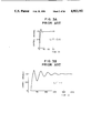
At start-up of a plant incorporating controllable objects such as processes and a PID controller for controlling the objects, it is general practice that the time response of a process variable appearing when a manipulated variable standing for an input signal to a process is changed stepwise is set in terms of a dead time characteristic and a primary time lag characteristic and PID control parameters are adjusted to optimum values on the basis of process gain K, dead time L and time constant T in these characteristics. Such a method for optimum adjustment of PID control parameters based on the step response includes a Ziegler-Nichols (ZN) method and a Chein-Hrones-Reswick (CHR) method. These methods feature simplified computations but are disadvantageous in the following points. As an example, when PID control parameters are adjusted, pursuant to the ZN method, for a controllable object having the dead time and secondary time lag characteristics, the control response changes as the command value changes in unit step, as graphically illustrated in FIG. 1A for L/T=0.14 and in FIG. 1B for L/T=1.0. Alternatively, when PID control parameters are adjusted pursuant to the CHR method, the control response changes as the command value changes in unit step, as graphically illustrated in FIG. 3A for L/T=0.14, in FIG. 3B for L/T=1 and in FIG. 3C for L/T=5. Thus, in the ZN method, the control response deviates from the stable limit at L/T=1 and in the CHR method the control response pulsates at L/T=5. Gathering from this, it is concluded that in any of the two methods excellent control can not be realized for large values of L/T.
On the other hand, as a general-purpose method for adjustment of PID control parameters' there is available a partial model matching method as described in, for example, "Design Method for Control System Based on Partial Knowledge of Controllable Object", Transactions of The Society of Instrument and Control Engineers, Vol 5, No. 4, pp 549/555, Aug., 1979.
The outline of the partial model matching method will now be described briefly. An arrangement for implementation of the partial model matching method is schematically illustrated, in block form, in FIG. 2. Referring to FIG. 2, reference numeral 1 designates a PID controller, 2 a process standing for an object to be controlled, 7 a process setter for setting a transfer function Gp (S) of the process, and 11 a control parameter determiner for determining optimum values of control parameters included in a transfer function Gc (S) of the PID controller.
According to the partial model matching method, the control parameters of the PID controller 1 are so determined that a closed loop transfer function W(S) covering a command value SV and a control variable PV coincides with a transfer function Gm (s, σ) of a reference model representing an ideal response of the control variable PV, where S is the Laplace operator and σ is a time scale coefficient. The transfer function Gp(S) of process 1 obtained from the process setter 7 is indicated by the following equation: ##EQU1## and the transfer function Gc(S) of PID controller 1 has the form of ##EQU2## where Kp, Ti and TD are control parameters respectively called proportional gain, integration time and differential time.
Accordingly, the closed loop transfer function W(s) is given by ##EQU3##
The transfer function Gm(s, o) of reference model is then given by ##EQU4## where α2, α3, α4 --are constants related to response waveforms.
By making equation (3) coincident with equation (4), the transfer function Gc(s) of PID controller is reduced to ##EQU5## By dividing the denominator by the numerator in equation (5), there results ##EQU6##
Considering that equation (1) equals equation (2.2) the following formulas can be obtained: ##EQU7##
From equation (10), the positive minimum real root of o is determined, which is substituted into equation (8) to determine Ti. The thus determined positive minimum real root and Ti are substituted into equations (7) and (9) to determine Kp to TD. In accordance with this method, coincidence of the closed loop transfer function W(s) with the reference model Gm(s, σ) of equation (4) prevails until the fourth order term of s in equation (4).
Due to the fact that the cubic algebraic equation shown in equation (10) is solved to determined σ, this method requires sophisticated computation for which microcomputer operations are unsuited.
SUMMARY OF THE INVENTION
The present invention intends to solve the prior art problems described previously and has for its object to provide a PID controller system wherein the adjustment work by the operator can be reduced to a great extent to prevent adjustment results from being differently affected by individuality of operators, the optimum tuning of control parameters can be effected without adopting the setting signal which tends to disturb the controllable object and changes in a dynamic characteristic of the controllable object can be detected rapidly without resort to any manual operations, whereby optimum control characteristics can always be maintained.
Another object of this invention is to provide a PID controller system which can obtain an excellent control characteristic even for a process in which the ratio of dead time to time constant is large and which can determine optimum values of PID control parameters in accordance with relatively simplified computation formulas to ensure that the PID controller system can be operated even by the aid of such a computing unit of small throughput as a microcomputer.
According to the invention, the above first object can be accomplished by a PID controller system comprising a control variable response shape recognizer for observing a control variable response shape appearing when a command value or set point changes or external disturbance is applied so as to determine necessary performance indexes a, control parameter modifier for evaluating the performance indexes qualitatively so as to deduce or estimate modified values of PID control parameters through fuzzy reasoning, and a controllability decision device for causing the control parameter modifier to operate when the performance indexes go beyond their permissible ranges.
As regards the attainment of the second object, based on observation that the conventional partial model matching method is difficult to solve the cubic algebraic equation in order to obtain the root necessary for determining the time scale coefficient, it has been found that the controllable object set in terms of the dead time and primary time lag characteristics can be approximated by a multi-order time lag characteristic in order that the time scale coefficient determined by making the closed loop transfer function of control variable coincide, for the command value, with the transfer function of reference model can be approximated by a linear equation of the dead time.
By using results of the approximation, the optimum values of PID control parameters are represented by functions of gain, dead time and time constant relating to processes and are determined pursuant to specified relations.
BRIEF DESCRIPTION OF THE DRAWINGS
FIGS. 1A and 1B are graphs showing prior art examples of control response obtained when the controllable object having the dead time and secondary time lag characteristics is controlled by changing the command value stepwise in a conventional PID controller in which PID control parameters are determined using the conventional ZN method, FIG. 1A being for L/T=0.14 and FIG. 1B being for L/T=1.
FIG. 2 is a block diagram of a prior art arrangement for implementation of control in accordance with the partial model matching method.
FIGS. 3A, 3B and 3C are graphs showing prior art examples of control response obtained when the controllable object having the dead time and secondary time lag characteristics is controlled by changing the command value stepwise in a conventional PID controller in which PID control parameters are determined using the conventional CHR method, FIG. 3A being for L/T=0.14,
FIG. 3B for L/T=1 and FIG. 3C for L/T=5.
FIG. 4 is a block diagram illustrating a PID controller system according to a first embodiment of the invention.
FIGS. 5A and 5B are graphs respectively showing membership functions for evaluating overshoot and membership functions for evaluating damping ratio, these membership functions being used in the FIG. 4 embodiment.
FIG. 6 shows an example of adjustment rules.
FIG. 7 is a graph showing membership functions for control parameter modifying coefficients.
FIG. 8 illustrates graphical representations useful to explain the manner of determining control parameter modifying coefficients.
FIG. 9 is a flow chart showing the schematic procedure of an auto-tuning function.
FIG. 10 is a graph showing results of autotuning according to the invention.
FIG. 11 is a block diagram illustrating a PID controller system according to a second embodiment of the invention.
FIGS. 12A and 12B are graphs respectively showing the control variable response shape obtained when the command value changes stepwise and the control variable response shape obtained when external disturbance is applied stepwise.
FIGS. 13A, 13B and 13C are graphs respectively showing membership functions for evaluating overshoot, membership functions for evaluating damping ratio and membership functions for evaluating period.
FIG. 14 shows an example of adjustment rules used for the respective types of membership function.
FIG. 15 is a graph showing membership functions for control parameter modifying coefficients.
FIG. 16 illustrates graphical representations useful to explain the manner of determining the control parameter modifying coefficients.
FIG. 17 is a flow chart showing the schematic procedure of another auto-tuning function.
FIG. 18A is a graph showing the autoturning response in the presence of large overshoot and hunting appearing in the initial control response shape.
FIG. 18B is a graph showing the autotuning response in the presence of over-damping appearing in the initial control response shape.
FIG. 19 is a block diagram illustrating a PID controller system according to still another embodiment of the invention.
FIG. 20./is a graph showing how L/T and δ/T are related to various reference models when PID control parameters are determined, pursuant to the partial model matching method, for the controllable object having the dead time and primary time lag characteristics.
FIGS. 21A, 21B and 21C are graphs respectively showing control response obtained when the dead time and secondary time lag characteristics are controlled under the conditions of L/T=0.14, L/T=1 and L/T=5 by changing the command value stepwise.
DESCRIPTION OF THE EMBODIMENTS
The invention will now be described by way of example with reference to the accompanying drawings.
As schematically shown in a block diagram of FIG. 4, a PID controller system according to a first embodiment of the invention comprises a PID controller 1, an object 2 to be controlled and an automatic adjuster 3.
The PID controller 1 performs a PID computation of a control difference e which is obtained from comparison of a command value SV with a control variable PV and produces a PID computation result which is applied as a manipulated variable MV to the controllable object 2. The automatic adjuster 3 comprises a control variable response shape recognizer 4, a control decider 5 and a control parameter modifier 6. The control parameter modifer 6 includes a control parameter modifying coefficient deducer 6a, an adjustment ruler 6b and a control parameter adjusting value calculator 6e.
Individual components described above will now be described specifically. The control variable response shape recognizer 4 always watches or supervises the command value or set point SV and control variable PV and begins to observe a control variable response at time that the control difference e exceeds a predetermined value after the control variable PV has been tuned to the command value SV. Concurrently with the commencement of the observation, the recognizer 4 retrieves extreme values of PV and ends the observation when the control variable PV is tuned to the command value SV. The recognizer 4 then computes the amount of overshoot and the damping ratio on the basis of a plurality of obtained extreme values and a change width of the command value SV.
In the absence of extreme values of the control variable PV, negative pseudo-values are set. The control decider 5 determines that the control parameters are of optimum values if the obtained overshoot and damping ratio respectively fall within their permissible ranges and ends the tuning. If any one of the overshoot and damping ratio does not fall within the permissible range, the decider 5 actuates the control parameter modifier 6.
The control parameter modifying coefficient deducer 6a, when based on the fuzzy reasoning method, will now be described. In order to qualitatively evaluate the amount of overshoot and the magnitude of damping ratio, membership functions as shown in FIGS. 5A and 5B are defined. In FIGS. 5A and 5B, E(i) where i=1-5 and D(i) where i=1-3 are constants for prescribing the the shape of the membership function, and PB, ZE and NB are names assigned to the membership functions with the view of evaluating the magnitude qualitatively. The names have the following meanings:
PB: Positive Big
ZE: Zero
NB: Negative Big.
In these Figures, ordinate represents the membership value G which is representative of the qualitative degree. Enumerated in FIG. 6 is an example of adjustment rules of the adjustment ruler 6b for PID control parameters which are prescribed by various control variable response shapes prepared using the member ship functions.
Taking a rule 1, for instance, this rule has the meaning "If E is PB and D is PB, then CKP is NB, CTD is PB and CTD is PB.", "if clause" being called a conditional clause and "then clause" being called a conclusive clause, where E is a modifying coefficient for the amount of overshoot, D is a modifying coefficient for the damping ratio, CKP is a modifying coefficient for the proportional gain, CTI is a modifying coefficient for the integration time and CTD is a modifying coefficient for the differential time. FIG. 7 graphically illustrates membership functions used for converting the qualitatively determined control parameter modifying coefficients into quantitative values. In FIG. 7, C(i) where i=1-5 is the constant for prescribing the shape of the membership functions, PB, ZE and NB are names which are assigned to the membership functions with the view of qualitatively indicating the magnitude of the control parameter modifying coefficients and which correspond to the names used in FIGS. 5A and 5B, and ordinate represents the membership value.
Taking the cases where rules 1 and 2 are applied, for instance, the manner of determining the control parameter modifying coefficients will now be described. Referring particularly to FIG. 8, there is illustrated the manner of determining the modifying coefficient CKP for the proportional gain in accordance with the fuzzy reasoning method. The qualitative degree of the amount of overshoot Eo and the damping ratio Do which are obtained from the control variable response shape recognizer 4 is determined using respective membership functions illustrated in FIGS. 5A and 5B. In the rule 1, Eo is Gep and Do is Gdp and in the rule 2 Eo is Gep and Do is Gdz. A product set (minimum value) computation is effected within the respective rules to determine the adaptability of each rule which is Gep for rule 1 and Gde for rule 2. Subsequently, membership functions contained in the conclusive clause of each rule are weighted by the adaptability of each rule, the weighted membership functions are subjected to a sum set (maximum value) computation, and the value of center of gravity of a sum set computation result is determined as an output value CKPo of the proportional gain modifying coefficient. Output values of the integration time modifying coefficient CTI and differential time modifying coefficient CTD may be determined in a similar manner.
The control parameter adjusting value calculator 6C multiplies the thus obtained PID control parameter modifying coefficient by the current value of the PID control parameter to determine the current adjusting value.
FIG. 9 shows a schematic flow chart of the procedure in the automatic adjuster 3. In step 10, SV and PV are inputted at a predetermined period and each time the SV and PV are inputted, a status flag indicative of the process status of the automatic adjuster 3 is decided in step 11. The status flag being "0" indicates a status for monitoring or supervising the control response, the status flag being "1" indicates a status for observing and evaluating the control response and the status flag being "2" indicates a status for computing the control parameters. With the status flag being "0", it is determined in step 12 whether the control difference exceeds a predetermined value. If the control difference exceeds the predetermined value, the status flag is set to "1" in step 13 and the procedure proceeds to the control response observing status. With the control difference not being in excess of the predetermined value, the control response supervising status is maintained. If the status flag is determined to b "1" in step 11, extreme values of PV are retrieved in step 14. This process is for each PV inputted and continues until it is determined in step 15 that PV is tuned to SV (completion of the observation). Upon completion of the observation, performance indexes (overshoot amount and damping ratio) are determined in step 16 by using results of the extreme value retrieval performed in step 14, the status flag is set to "2" in step 17 and the procedure proceeds to the control parameter computing status. The process flow described till now corresponds to the operation of the control response shape recognizer 4.
If it is decided in step 11 that the status flag is "2", it is determined in step 18 whether the observed control response is optimum by using decision as to whether the performance indexes determined in step 16 fall within their permissible ranges. This process corresponds to the operation of the control decider 5. Only in the case where the control response is not optimum, the modifying coefficients for the control parameters and determined in step 19 and adjusting values for the control parameters are determined in step 20. The thus obtained control parameter adjusting values are used for the control computation in the PID controller 1. The step 16 corresponds to the operation of the control parameter modifying coefficient deducer 6a and adjustment ruler 6b and the step 20 corresponds to the operation of the control parameter adjusting value calculator 6c. When the control response is decided to be optimum in step 18 and the process in step 20 ends, the status flag is reset to "0" in step 21 and the procedure returns to the control response supervising status.
The PID controller system of this embodiment is operated for the controllable object having the secondary time lag and dead time characteristics, exhibiting results as graphically illustrated in FIG. 10. Particularly, the time response of the control variable PV obtained when the command value SV is changed is illustrated in FIG. 10. At time that the SV changes stepwise initially, the initial control response of PV follows the change of SV with the overshoot amount E being 50% and the damping ratio D being 0.6, thereafter the performance indexes (overshoot amount and damping ratio) obtained from observation results of twice trials which correspond to the twice step changes of the SV can fall within predetermined permissible ranges of the performance indexes, indicating attainment of the optimum tuning, and hence the tunning completes at the third trial.
As described previously, the auto-tuning of control parameters can be achived using a small number of adjustment rules.
Although all the membership functions are of a triangular form for illustration purpose only, they are not limited thereto and may be realize with a quadratic curve or an exponential curve without disturbing the essentiality of the invention. Further, the number of membership functions may desirably be set.
Referring to FIGS. 11 to FIG. 18A and FIG. 18B, a PID controller system according to a second embodiment of the invention will be described. This embodiment differs from the first embodiment described in connection with FIGS. 4 to 10 in that in addition to the overshoot and damping ratio, the ratio of period is employed as a control parameter. Since a block configuration form of FIG. 11 is essentially identical to that of FIG. 4 relevant to the first embodiment with the only exception that the former is so modified as to handle the ratio of period as an additional observation parameter, reference numerals in FIG. 4 are added with dash to designate blocks or components of FIG. 11 which correspond to those of FIG. 4. Observation and control are actually carried out in a manner as will be described below.
A control variable response shape recognizer 4' always supervises the command value SV and control variable PV and begins to observe a control variable response at time that the control difference e exceeds a predetermined value after the control variable PV has been tuned to the command value SV. Concurrently with the commencement of the observation, the recognizer 4' retrieves extreme values of control variable PV and ends the observation when the control variable is tuned to the command value SV. The recognizer 4' then computes the amount of overshoot, damping ratio and period ratio on the basis of a plurality of obtained extreme values and times the extreme values occur. The manner of determining these control parameters will be described with reference to FIGS. 12A and 12B. FIG. 12A particularly illustrates an example of time response of the control variable PV obtained when the command value SV changes stepwise from Y0 to Y1 at time t0, indicating that extreme values X1, X2 and X3 occur at times t1, t2 and t3 and the tuning is completed at time t4. The overshoot amount E, damping ratio D and period T are given by ##EQU8##
Accordingly, given that the previous value of period is T1, the period ratio R is expressed by ##EQU9##
FIG. 12B particularly illustrates an example of time response of the control variable PV obtained when an external disturbance is applied to the input of the controllable object with the command value maintained at Y0, indicating that extreme values X1, X2, X3 and X4 occur at times t1, t2, t3 and t4 and the tuning is completed at time t5. The overshoot amount E, damping ratio D and period T are given by ##EQU10##
If no extreme value apperas in the control variable reponse shape as the command value changes or if no second-occurrence extreme value appears in the control variable response shape when the external disturbance is applied, the overshoot is set to a negative value and the period is set to zero. If only one extreme value occurs in the control variable response shape in response to the change of the command value or if only two extreme values occur in the control variable response shape in response to the application of the external disturbance, the time difference referenced to the tuning time is used as the period.
A control decider 5' determines that the control parameter are of optimum values the obtained overshoot and damping ratio respectively fall within their permissible ranges and ends the tuning. If any one of the overshoot and damping ratio does not fall within the permissible range, the decider 5' actuates a control parameter modifier 6'.
A control parameter modifying coefficient deducer 6a', when based on the fuzzy reasoning method, will now be described. In order to qualitatively evaluate the amount of overshoot and the magnitude of damping ratio and period ratio, membership functions as shown in FIGS. 13A, 13B and 13C are defined. In FIGS. 13A to 13C, E(i) where i=1-5, D(i) where i=1-3 and R(i) where i=1-3 are constants for prescribing the shape of the membership function, and PB, PM, ZE and NB are names assigned to the membership functions with the view of evaluating the magnitude qualitutively. As in the case of the first embodiment, the names have the following meanings:
PB: Positive Big
PM: Positive Medium
ZE: Zero
NB: Negative Big
In these Figures, ordinate represents the membership value G which is representative of the qualitutive degree. Enumerated in FIG. 14 is an example of adjustment rules of an adjustment ruler 6b' for PID control parameters which are prescribed by various control variable response shapes prepared using the membership functions.
Taking a rule 2, for instance, this rule has the meaning "If E is PB, D is PM and R is PR, then CKP is NR, CTI is NB and CTD is ZE", "if clause" being called a conditional clause and "then clause" being called a conclusive clause, where E is a modifying coefficient for the overshoot amount, D is a modifying coefficient for the damping ratio, R is a modifying coefficient for the period ratio, CKP is a modifying coefficient for the proportional gain, CTI is a modifying coefficient for the integration time and CTD is a modifying coefficient for the differential time. FIG. 15 graphically illustrates membership functions used for converting the qualitatively determined control parameter modifying coefficients into quantitative values. In FIG. 15, C(i) where i=1-5 is the constant for prescribing the shape of the membership functions, PB, ZE and NB are names which are assigned to the membership functions with the view of qualitatively indicating the magnitude of the control parameter modifying coefficients and which correspond to the names used in FIGS. 13A, 13B and 13C, and ordinate represents the membership value.
Taking the cases where rules 2 and 3 are applied, for instance, the manner of determining the control parameter modifying coefficients will now be described. Referring particularly to FIG. 16, there is illustrated the manner of determining the modifying coefficient CKP for the proportional gain in accordance with the fuzzy reasoning method. The qualitative degree of the overshoot amount Eo, damping ratio Do and period ratio Ro which are obtained from the control variable shape recognizer 4' is determined using respective membership functions illustrated in FIGS. 13A, 13B and 13C. In the rule 2, Eo is Gep, Do is Gdm and Ro is Grp and in the rule 3, Eo is Gep, Do is Gdm and Ro is Grz. A product set (minimum value) computation is effected within the respective rules to determine the adaptability of each rule which is Grp for rule 2 and Grz for rule 3. Subsequently, membership functions contained in the conclusive clause of each rule are weighted by the adaptability of each rule, the weighted membership functions are subjected to a sum set (maximum value) computation, and the value of center of gravity of a sum set computation result is determined as an output value (KPo of the proportional gain modifying coefficient. Output values of the integration time modifying coefficient (TI and differential time modifying coefficient CTD may be determined in a similar manner.
A control parameter adjusting value calculator 6c' multiplies the thus obtained PID control parameter modifying coefficient by the current value of the PID control parameter to determine a current adjusting value.
FIG. 17 shows a schematic flow chart of the procedure in the automatic adjuster 3'.
FIG. 17 shows a schematic flow chart of the procedure in the automatic adjuster 3'. In step 10', SV and PV are inputted at a predetermined period and each time the SV and PV are inputted, a status flag indicative of the process status of the automatic adjuster 3' is decided in step 11'. The status flag being "0" indicates a status for monitoring or supervising the control response, the status flag being "1" indicates a status for observing and evaluating the control response and the status flag being "2" indicates a status for computing the control parameters. With the status flag being "0", it is determined in step 12' whether the control difference exceeds a predetermined value. If the control difference exceeds the predetermined value, the status flag is set to "1 38 in step 3' and the procedure proceeds to the control response observing status. With the control difference not being in excess of the predetermined value, the control response supervising status is maintained. If the status flag is determined to be "1" in step 11', extreme values of PV are retrieved in step 14'. This process is for each PV inputted and continues until it is determined in step 15' that PV is tuned to SV (completion of the observation). Upon completion of the observation, performance indexes (overshoot amount and damping ratio) are determined in step 16' by using results of the extreme value retrieval performed in step 14', the status flag is set to "2" in step 17' and the procedure proceeds to the control parameter computing status. The process flow described till now corresponds to the operation of the control response shape recognizer 4'.
If it is decided in step 11' that the status flag is "2", it is determined in step 18' whether the observed control response is otpimum by using decision as to whether the performance indexes determined in step 16' fall within their permissible ranges. This process corresponds to the operation of the control decider 5'. Only in the case where the control response is not optimum, the modifying coefficients for the control parameters are determined in step 19' and adjusting values for the control parameters are determined in step 20'. The thus obtained control parameter adjusting values are used for the control computation in the PID controller 1. The step 16' corresponds to the operation of the control parameter modifying coefficient deducer 6a' and adjustment ruler 6b' and the step 20' corresponds to the operation of the control parameter adjusting value calculator 6c'. When the control response is decided to be optimum in step 18' and the process in step 20' ends, the status flag is reset to "0" in step 21' and the procedure returns to the control response supervising status.
The PID controller system of this embodiment is operated for the controllable object having the secondary time lag and dead time characteristics, exhibiting results as graphically illustrated in FIGS. 18A and 18B. Particularly, the time response of the control variable PV obtained when the command value SV is changed is shown with FIG. 18A indicating an instance where the overshoot amount E for the initial control response is 50% and the damping ratio D is 0.6 and FIG. 18B indicating an instance where the initial control response is placed in the over damping condition. It will be appreciated that in any of these instances the substantially optimum tuning can be reached through twice trials.
As described above, according to this second embodiment of the invention, not only the auto-tuning of control parameters can be achieved using a small number of adjustment rules but also the tuning can be obtained at quick response by evaluating the control variable on the basis of the period ratio. The control variable response shape recognizer can also use, as the fourth performance index, a control variable corresponding to the rise time of the previously-described control variables, the ratio between the previous and current values of occurrence time of the first-occurrence extreme value or the ratio between the previous and current values of tuning time of the control variable. The control parameter modifier 6' uses the membership functions of a triangular form but the form of the membership functions is not limited thereto and may be a quadratic curve or an exponential curve without disturbing the essentiality of the invention. Further, the number of membership functions may desirably be set.
Referring to FIG. 19 and the ensuring Figures, a PID controller system according to still another embodiment of the invention will be described. As schematically diagrammatically shown in FIG. 19, the PID controller system of this embodiment comprises a PID controller 1, a process 2 standing for an object to be controlled, and an automatic adjuster 3" including a process setter 7, a proportional gain calculator 8, an integration time calculator 9 and a differential time calculator 10.
This embodiment of FIG. 19 is particularly suitable for setting control parameters of the PID controller 1 to optimum values at the start-up of a plant. The process setter 7 sets the dynamic characteristic of the process 2 in terms of the dead time/primary time lag characteristic and determines gain K, dead time L and time constant T of the process from the dead time and primary time lag characteristics. The proportional gain calculator 8 determines proportional gain Kp as a function of the gain K, dead time L and time constant T of the process obtained from the process setter 7, the integration time calculator 9 determines integration time TI as a function of the dead time L and time constant T obtained from the process setter 7, and the differential time calculator 10 determines differential time TD as a function of the dead time L and time constant T obtained from the process setter 7.
The calculators 8, 9 and 10 feature the present embodiment and operate for computation based on the following theory.
The dead time/primary time lag characteristic Gp(s) set by the process setter 7 is given by ##EQU11##
The dead time transfer function of equation (11) can be expanded and reduced by Maclaurin's expansion to ##EQU12##
By applying the partial model matching method to the process dynamic characteristic of equation (12), the following formulas result from equations (7) to (10) ##EQU13##
Unless there is a positive real root of σ in equation (16), the partial model matching method can not settle the command control response indicated by equation (4).
Then, the relation between the time ratio L/T to the time constant and the time scale coefficient ratio σ/T to the time constant is examined using various reference models as the parameter to obtain results as graphically illustrated in FIG. 20. The transfer functions of the reference models used in the examination are given as follows:
(1) Kitamori model ##EQU14##
(2) Butter worth model ##EQU15##
(3) Biromial model ##EQU16##
(4) ITAE minimum model ##EQU17##
The variable σ corresponds to the rise time of control response and reasonably it will increase as L increases. Thus, by studying FIG. 20, it will be understood that for Kitamori model being used as the reference model, reasonable values of σ/T can be obtained over a wide range of L/T from 0 (zero) to 10. This σ/T is then approximated by ##EQU18##
From equation (21), the time scale coefficient σ reduces to ##EQU19##
Then, by substituting equation (22) into equations (13) to (15), the proportional gain Kp, integration time Ti and differential time TD can be determined as follows: ##EQU20##
Therefore, the proportional gain calculator 8 computes equation (23) to determine the optimum value Kp of proportional gain on the basis of K, L and T, the integration time calculator 9 computes equation (24) to determine the optimum value Ti of integration time and the differential time calculator 10 computes equation (25) to determined the optimum value TD of differential time, thereby ensuring that the proportional gain Kp, integration time Ti and fifferential time TD of the PID controller 1 can respectively be set and
2 may be
In equation (25), the term of L2 may be neglected for L being smaller than T and the differential time TD may be computed in accordance with ##EQU21##
With the embodiment of FIG. 19, the control response of the object process having the dead time and secondary time lag characteristics as in the case of FIGS. 1A, 1B, 3A, 3B and 3C is examined by changing the command value in unit step to obtain results as graphically illustrated in FIG. 21A for L/T=0.14, in FIG. 21B for L/T=1 and in FIG. 21C for L/T=5, demonstrating that even for L/T being large, an excellent control characteristic can be obtained.
Although all of the foregoing embodiments have been described in terms of hardware for clarity of explanation, they may obviously be realized with software by the aid of a computer in a similar manner.

Claims (9)

We claim:
1. A PID controller system comprising:
a PID controller for receiving a difference between a set point and a controlled variable of a process to be controlled and delivering a manipulated variable to the process, the process being operated by the manipulated variable to produce the controlled variable; and
automatic adjuster means including
a control variable response shape recognizer means for receiving the set point and controlled variable of the process and determining a plurality of performance indexes on the basis of a response shape of the controlled variable obtained when the set point is changes or a disturbance is applied;
a control parameter modifier means having a plurality of evaluation means for utilizing a plurality of performance indexes, and interpreting magnitudes of the plurality of performance indexes and defining magnitudes of control parameter modifying coefficients by using a plurality of qualitative values, and inferring the control parameter modifying coefficients through fuzzy inference by using a plurality of adjusting rules which express an interrelation between the performance indexes and the control parameter modifying coefficients by the plurality of qualitative values;
said automatic adjuster means being responsive to a variable relating to the manipulation of said PID controller and the controlled variable from the process to obtain performance indexes and preparing, on the basis of the performance indexes, optimum control parameters for tuning the controlled variable to the set point, the optimum control parameters being fed back from said automatic adjuster means to said PID controller.
2. A PID controller system according to claim 1 wherein said plurality of performance indexes are overshoot, damping ratio.
3. A PID controller system according to claim 1 wherein said plurality of performance indexes are overshoot, damping ratio and period ratio defining a ratio between the previous and current values of the period.
4. A PID controller system according to claim 1 wherein said plurality of performance indexes are overshoot, damping ratio and rise time ratio defining a ratio between previous and current values of the rise time.
5. A PID controller system according to claim 1 wherein said plurality of performance indexes are overshoot, damping ratio and tuning time ratio defining a ratio between the previous and current values of the tuning time.
6. A PID controller system comprising:
a PID controller for receiving a difference between a set point and a controlled variable of a process to be controlled and delivering a manipulated variable to the process, the process being operated by the manipulated variable to produce the controlled variable; and
automatic adjuster means, including a process estimator means for controlling the process and for producing gain, dead time and time constant characteristics to be utilized in the process;
proportional gain calculator means responsive to the gain, dead time and time constant characteristics produced by said process estimator means to set the proportional gain;
an integral time calculator means responsive to the dead time and time constant characteristics produced by said process estimator means to set the integral time; and
derivative time calculator means responsive to the dead time and time constant characteristics produced by said processor estimator means to set a derivative time.
7. A PID controller system according to claim 6, wherein said integral time calculator means determines the integral time by adding the dead time characteristic and the time constant characteristic, said proportional gain calculator means determining the proportional gain by dividing the integral time resulting from addition by the product term of the gain and dead time characteristics, and said derivative time calculator means determines the derivative time by dividing the product term of the gain and mean time characteristics by the integral time resulting from the addition.
8. A PID controller system according to claim 6 wherein output Kp of said proportional gain calculator means, output Ti of said integral time calculator means and output TD of said derivative time calculator means are respectively determined by ##EQU22## where K is the gain characteristic, T is the dead time characteristic and L is the time constant characteristic.
9. A PID controller system according to claim 6, wherein said automatic adjuster means is responsive to a variable relating to the manipulation of said PID controller and the controlled variable from the process to obtain performance indexes and prepares, on the basis of said performance indexes, optimum control parameters for tuning the controlled variable to the set point, the optimum control parameters being fed back from said automatic adjuster means to said PID controller.
US07/177,428 1987-04-03 1988-04-01 Pid controller system Expired - Fee Related US4903192A (en)

Applications Claiming Priority (6)

Application Number Priority Date Filing Date Title
JP62080976A JPS63247801A (en) 1987-04-03 1987-04-03 Pid controller
JP62-80976 1987-04-03
JP62-201733 1987-08-14
JP62201733A JP2650918B2 (en) 1987-08-14 1987-08-14 PID controller
JP62-237201 1987-09-24
JP62237201A JP2585294B2 (en) 1987-09-24 1987-09-24 PID controller

Publications (1)

Publication Number Publication Date
US4903192A true US4903192A (en) 1990-02-20

Family

ID=27303446

Family Applications (1)

Application Number Title Priority Date Filing Date
US07/177,428 Expired - Fee Related US4903192A (en) 1987-04-03 1988-04-01 Pid controller system

Country Status (2)

Country Link
US (1) US4903192A (en)
DE (1) DE3811086A1 (en)

Cited By (61)

* Cited by examiner, † Cited by third party
Publication number Priority date Publication date Assignee Title
US5025499A (en) * 1988-04-13 1991-06-18 Hitachi, Ltd. Process control method and control system
US5043862A (en) * 1988-04-07 1991-08-27 Hitachi, Ltd. Method and apparatus of automatically setting PID constants
EP0482900A2 (en) * 1990-10-24 1992-04-29 Honeywell Inc. Adaptive controller in a process control system and a method therefor
US5111531A (en) * 1990-01-08 1992-05-05 Automation Technology, Inc. Process control using neural network
GB2251092A (en) * 1990-09-10 1992-06-24 Nissei Plastics Ind Co Temperature control in injection moulding.
US5153807A (en) * 1988-09-21 1992-10-06 Hitachi, Ltd. Self-tuning controller apparatus and process control system
US5159547A (en) * 1990-10-16 1992-10-27 Rockwell International Corporation Self-monitoring tuner for feedback controller
US5172579A (en) * 1989-07-31 1992-12-22 Kabushiki Kaisha Toshiba Steering control apparatus for rolled plates
US5214576A (en) * 1989-12-28 1993-05-25 Idemitsu Kosan Co., Ltd. Compound control method for controlling a system
US5235835A (en) * 1988-12-28 1993-08-17 Furukawa Aluminum Co., Ltd Method and apparatus for controlling flatness of strip in a rolling mill using fuzzy reasoning
US5239616A (en) * 1989-04-14 1993-08-24 Omron Corporation Portable fuzzy reasoning device
US5245528A (en) * 1989-03-20 1993-09-14 Hitachi, Ltd. Process control apparatus and method for adjustment of operating parameters of controller of the process control apparatus
US5251124A (en) * 1991-04-30 1993-10-05 Omron Corporation Fuzzy controller apparatus and method for steady state control
US5272621A (en) * 1988-11-18 1993-12-21 Nippon Denki Garasu Kabushiki Kaisha Method and apparatus using fuzzy logic for controlling a process having dead time
US5295061A (en) * 1990-04-20 1994-03-15 Sanyo Electric Co., Ltd. Control parameter tuning unit and a method of tuning parameters for a control unit
US5319539A (en) * 1992-05-27 1994-06-07 The Foxboro Company Method and apparatus for generating an optimal gain of process control equipment
US5325288A (en) * 1992-07-16 1994-06-28 Sato Nobuyasu Automatic PID controller in which the ratio of the control target value to the control signal is used to optimize performance
US5335165A (en) * 1992-05-27 1994-08-02 The Foxboro Company Method and apparatus for adaptive deadtime process control
US5341288A (en) * 1992-05-27 1994-08-23 The Foxboro Company Method and apparatus for analyzing process characteristics
DE4321284A1 (en) * 1993-06-26 1995-02-09 Abb Research Ltd Method and device for slip control
US5394322A (en) * 1990-07-16 1995-02-28 The Foxboro Company Self-tuning controller that extracts process model characteristics
US5397973A (en) * 1993-09-16 1995-03-14 Allen-Bradley Company, Inc. Gain control for fuzzy logic controller
US5404289A (en) * 1993-08-30 1995-04-04 National University Of Singapore Controller apparatus having improved transient response speed by means of self-tuning variable set point weighting
US5406474A (en) * 1990-07-16 1995-04-11 The Foxboro Company Self-tuning controller
US5406496A (en) * 1992-07-20 1995-04-11 Recon/Optical, Inc. Adaptive digital controller with automatic plant tuning
US5420785A (en) * 1993-05-26 1995-05-30 The Foxboro Company Self-tuning deadtime process controller
US5426357A (en) * 1993-05-25 1995-06-20 Satou; Nobuyasu Control device for induction motor
US5479567A (en) * 1991-09-03 1995-12-26 Fuji Electric Co., Ltd. Fuzzy feedback controller and method
US5497063A (en) * 1993-09-16 1996-03-05 Allen-Bradley Company, Inc. Fuzzy logic servo controller
US5537388A (en) * 1994-03-02 1996-07-16 The Foxboro Company Method and apparatus for characterizing and compensating for non-linear components
US5541833A (en) * 1987-03-30 1996-07-30 The Foxboro Company Multivariable feedforward adaptive controller
US5568379A (en) * 1991-11-25 1996-10-22 Siemens Aktiengesellschaft Method for controlling dynamic nth-order systems
US5587896A (en) * 1990-07-16 1996-12-24 The Foxboro Company Self-tuning controller
US5652485A (en) * 1995-02-06 1997-07-29 The United States Of America As Represented By The Administrator Of The U.S. Environmental Protection Agency Fuzzy logic integrated electrical control to improve variable speed wind turbine efficiency and performance
EP0829784A1 (en) * 1996-09-12 1998-03-18 Applied Materials, Inc. Adaptive temperature controller and method of operation
US5796608A (en) * 1995-07-06 1998-08-18 Hartmann & Braun A.G. Self controllable regulator device
USRE36421E (en) * 1988-09-28 1999-11-30 Omron Corporation Fuzzy controller for selecting an input signal
US6112125A (en) * 1995-03-08 2000-08-29 Silicon Systems, Inc. Self-tuning method and apparatus for continuous-time filters
US6171066B1 (en) * 1997-06-09 2001-01-09 Smc Kabushiki Kaisha Automatic pneumatic pressure control apparatus and method of controlling same
US6438532B1 (en) * 1997-01-25 2002-08-20 Kabushiki Kaisha Toshiba Adjustment rule generating and control method and apparatus
US6445962B1 (en) * 1999-03-15 2002-09-03 Fisher Rosemount Systems, Inc. Auto-tuning in a distributed process control environment
DE10213533A1 (en) * 2002-03-26 2003-10-16 Siemens Ag Method and controller for regulating at least one component of a technical system
DE10302585A1 (en) * 2003-01-22 2004-08-12 Endress + Hauser Wetzer Gmbh + Co Kg Optimization of PID regulation parameters of a PID regulator by setting minimum control values using minimum values in the proportional regions of control values
US20040170138A1 (en) * 2003-02-28 2004-09-02 Blevins Terrence L. High speed auto-tuning loop
US6912426B1 (en) 1999-09-24 2005-06-28 Dr. Johannes Heidenhain Gmbh Method for determining time constants of a reference model in a cascade controlling circuit
US20050222728A1 (en) * 2004-04-01 2005-10-06 Hac Aleksander B Feedforward control of motor vehicle roll angle
US7054846B1 (en) * 1997-08-11 2006-05-30 Siemens Ag Temporally discrete dynamic fuzzy logic control elements
US20090005889A1 (en) * 2007-06-28 2009-01-01 Rockwell Automation Technologies, Inc. Model predictive control system and method for reduction of steady state error
US20100185304A1 (en) * 2009-01-22 2010-07-22 Khalid El-Rifai Method and Apparatus for Hybrid Resetting States Proportional-Integral-Derivative and Lag Controllers
US20110190909A1 (en) * 2010-02-01 2011-08-04 Johnson Controls Technology Company Systems and methods for increasing feedback controller response times
FR2956237A1 (en) * 2010-02-09 2011-08-12 Commissariat Energie Atomique DEVICE FOR UPDATING A PHOTOMETRIC MODEL
US20120323350A1 (en) * 2010-06-16 2012-12-20 Minoru Yamamoto Support system for setting equipment parameters
CN103439887A (en) * 2013-07-31 2013-12-11 广东电网公司电力科学研究院 PI controller parameter setting method and system with optimal lower order system ITAE
CN103631135A (en) * 2013-11-28 2014-03-12 长春理工大学 Vector method-based method for setting parameter of fractional order PI lambda controller
CN104739620A (en) * 2013-12-30 2015-07-01 三星电子株式会社 Motion assistive apparatus and method of controlling the same
CN104850010A (en) * 2015-03-18 2015-08-19 北京工业大学 Intelligent control method for pulsation vacuum sterilizer based on fuzzy control
US10871497B2 (en) * 2018-01-05 2020-12-22 Illumina, Inc. Predicting reagent chiller instability and flow cell heater failure in sequencing systems
CN112951462A (en) * 2020-11-27 2021-06-11 中广核工程有限公司 Variable parameter design and setting method, device and equipment for closed-loop control system of nuclear power station
EP3904971A1 (en) * 2020-04-29 2021-11-03 Honeywell International Inc. Pid controller autotuner using machine learning approaches
CN114115305A (en) * 2021-11-01 2022-03-01 武汉大学 Control system design method of high-precision remote sensing small satellite with fast maneuvering posture
US11288576B2 (en) 2018-01-05 2022-03-29 Illumina, Inc. Predicting quality of sequencing results using deep neural networks

Families Citing this family (5)

* Cited by examiner, † Cited by third party
Publication number Priority date Publication date Assignee Title
DE3943093C2 (en) * 1988-12-28 1995-05-18 Furukawa Aluminium Method for controlling the flatness of a strip produced in a roll stand and device for carrying it out
EP0554479B1 (en) * 1992-02-04 1997-04-23 Siemens Aktiengesellschaft Method for controlling technical processes with several controllers
DE4204047C2 (en) * 1992-02-12 2003-12-24 Bosch Gmbh Robert Method and device for positioning an actuator in a motor vehicle
US5847952A (en) * 1996-06-28 1998-12-08 Honeywell Inc. Nonlinear-approximator-based automatic tuner
DE29709588U1 (en) * 1997-06-02 1997-11-06 Ps Automation Gmbh Ges Fuer An Intelligent control and regulating device

Citations (6)

* Cited by examiner, † Cited by third party
Publication number Priority date Publication date Assignee Title
US3934124A (en) * 1974-06-24 1976-01-20 Gabriel Edwin Z Self-organizing controllers
US4441151A (en) * 1977-11-04 1984-04-03 Toyo Systems, Ltd. Apparatus for tuning PID controllers in process control systems
US4602326A (en) * 1983-12-12 1986-07-22 The Foxboro Company Pattern-recognizing self-tuning controller
US4669040A (en) * 1984-09-19 1987-05-26 Eurotherm Corporation Self-tuning controller
US4754391A (en) * 1985-09-18 1988-06-28 Yamatake-Honeywell Co. Ltd. Method of determining PID parameters and an automatic tuning controller using the method
US4768143A (en) * 1986-10-09 1988-08-30 The Babcock & Wilcox Company Apparatus and method using adaptive gain scheduling algorithm

Family Cites Families (2)

* Cited by examiner, † Cited by third party
Publication number Priority date Publication date Assignee Title
DE3005103A1 (en) * 1980-02-12 1981-08-20 Konstantin Dipl.-Ing. 8910 Landsberg Meyl Electrical adaptive control system - provides optimised regulator performance by comparison of regulator standard function with optimum transfer function
DE3335219A1 (en) * 1983-09-29 1985-04-11 Gossen Gmbh, 8520 Erlangen Digital multiple controller

Patent Citations (6)

* Cited by examiner, † Cited by third party
Publication number Priority date Publication date Assignee Title
US3934124A (en) * 1974-06-24 1976-01-20 Gabriel Edwin Z Self-organizing controllers
US4441151A (en) * 1977-11-04 1984-04-03 Toyo Systems, Ltd. Apparatus for tuning PID controllers in process control systems
US4602326A (en) * 1983-12-12 1986-07-22 The Foxboro Company Pattern-recognizing self-tuning controller
US4669040A (en) * 1984-09-19 1987-05-26 Eurotherm Corporation Self-tuning controller
US4754391A (en) * 1985-09-18 1988-06-28 Yamatake-Honeywell Co. Ltd. Method of determining PID parameters and an automatic tuning controller using the method
US4768143A (en) * 1986-10-09 1988-08-30 The Babcock & Wilcox Company Apparatus and method using adaptive gain scheduling algorithm

Non-Patent Citations (6)

* Cited by examiner, † Cited by third party
Title
"Expert Self Tuning Control System", Measurement Technology, pp. 66-72, Sep. 1986.
"Method of Designing Control System Based on a Partial Knowledge of Control Object", Transactions of the Society of Instrument and Control Engineers, vol. 5, No. 4, 1979.
"PID Self Tuning by Expert Method", Measurement Technology, pp. 52-59, Sep. 1986.
Expert Self Tuning Control System , Measurement Technology, pp. 66 72, Sep. 1986. *
Method of Designing Control System Based on a Partial Knowledge of Control Object , Transactions of the Society of Instrument and Control Engineers, vol. 5, No. 4, 1979. *
PID Self Tuning by Expert Method , Measurement Technology, pp. 52 59, Sep. 1986. *

Cited By (85)

* Cited by examiner, † Cited by third party
Publication number Priority date Publication date Assignee Title
US5541833A (en) * 1987-03-30 1996-07-30 The Foxboro Company Multivariable feedforward adaptive controller
US5043862A (en) * 1988-04-07 1991-08-27 Hitachi, Ltd. Method and apparatus of automatically setting PID constants
US5025499A (en) * 1988-04-13 1991-06-18 Hitachi, Ltd. Process control method and control system
US5153807A (en) * 1988-09-21 1992-10-06 Hitachi, Ltd. Self-tuning controller apparatus and process control system
USRE36421E (en) * 1988-09-28 1999-11-30 Omron Corporation Fuzzy controller for selecting an input signal
US5272621A (en) * 1988-11-18 1993-12-21 Nippon Denki Garasu Kabushiki Kaisha Method and apparatus using fuzzy logic for controlling a process having dead time
US5235835A (en) * 1988-12-28 1993-08-17 Furukawa Aluminum Co., Ltd Method and apparatus for controlling flatness of strip in a rolling mill using fuzzy reasoning
US5245528A (en) * 1989-03-20 1993-09-14 Hitachi, Ltd. Process control apparatus and method for adjustment of operating parameters of controller of the process control apparatus
US5239616A (en) * 1989-04-14 1993-08-24 Omron Corporation Portable fuzzy reasoning device
US5172579A (en) * 1989-07-31 1992-12-22 Kabushiki Kaisha Toshiba Steering control apparatus for rolled plates
US5214576A (en) * 1989-12-28 1993-05-25 Idemitsu Kosan Co., Ltd. Compound control method for controlling a system
US5111531A (en) * 1990-01-08 1992-05-05 Automation Technology, Inc. Process control using neural network
US5295061A (en) * 1990-04-20 1994-03-15 Sanyo Electric Co., Ltd. Control parameter tuning unit and a method of tuning parameters for a control unit
US5406474A (en) * 1990-07-16 1995-04-11 The Foxboro Company Self-tuning controller
US5587896A (en) * 1990-07-16 1996-12-24 The Foxboro Company Self-tuning controller
US5394322A (en) * 1990-07-16 1995-02-28 The Foxboro Company Self-tuning controller that extracts process model characteristics
GB2251092A (en) * 1990-09-10 1992-06-24 Nissei Plastics Ind Co Temperature control in injection moulding.
GB2251092B (en) * 1990-09-10 1994-05-11 Nissei Plastics Ind Co A thermocontrol method for an injection molding machine
US5159547A (en) * 1990-10-16 1992-10-27 Rockwell International Corporation Self-monitoring tuner for feedback controller
EP0482900A3 (en) * 1990-10-24 1993-02-10 Honeywell Inc. Adaptive controller in a process control system and a method therefor
US5170341A (en) * 1990-10-24 1992-12-08 Honeywell Inc. Adaptive controller in a process control system and a method therefor
AU642042B2 (en) * 1990-10-24 1993-10-07 Honeywell Inc. Adaptive controller in a process control system and a method therefor
EP0482900A2 (en) * 1990-10-24 1992-04-29 Honeywell Inc. Adaptive controller in a process control system and a method therefor
US5251124A (en) * 1991-04-30 1993-10-05 Omron Corporation Fuzzy controller apparatus and method for steady state control
US5479567A (en) * 1991-09-03 1995-12-26 Fuji Electric Co., Ltd. Fuzzy feedback controller and method
US5568379A (en) * 1991-11-25 1996-10-22 Siemens Aktiengesellschaft Method for controlling dynamic nth-order systems
US5341288A (en) * 1992-05-27 1994-08-23 The Foxboro Company Method and apparatus for analyzing process characteristics
US5335165A (en) * 1992-05-27 1994-08-02 The Foxboro Company Method and apparatus for adaptive deadtime process control
US5319539A (en) * 1992-05-27 1994-06-07 The Foxboro Company Method and apparatus for generating an optimal gain of process control equipment
US5325288A (en) * 1992-07-16 1994-06-28 Sato Nobuyasu Automatic PID controller in which the ratio of the control target value to the control signal is used to optimize performance
US5406496A (en) * 1992-07-20 1995-04-11 Recon/Optical, Inc. Adaptive digital controller with automatic plant tuning
US5426357A (en) * 1993-05-25 1995-06-20 Satou; Nobuyasu Control device for induction motor
US5420785A (en) * 1993-05-26 1995-05-30 The Foxboro Company Self-tuning deadtime process controller
CN1035315C (en) * 1993-06-26 1997-07-02 Abb研究有限公司 Process and device for slip control
DE4321284A1 (en) * 1993-06-26 1995-02-09 Abb Research Ltd Method and device for slip control
US5404289A (en) * 1993-08-30 1995-04-04 National University Of Singapore Controller apparatus having improved transient response speed by means of self-tuning variable set point weighting
US5497063A (en) * 1993-09-16 1996-03-05 Allen-Bradley Company, Inc. Fuzzy logic servo controller
US5397973A (en) * 1993-09-16 1995-03-14 Allen-Bradley Company, Inc. Gain control for fuzzy logic controller
US5537388A (en) * 1994-03-02 1996-07-16 The Foxboro Company Method and apparatus for characterizing and compensating for non-linear components
US5652485A (en) * 1995-02-06 1997-07-29 The United States Of America As Represented By The Administrator Of The U.S. Environmental Protection Agency Fuzzy logic integrated electrical control to improve variable speed wind turbine efficiency and performance
US6112125A (en) * 1995-03-08 2000-08-29 Silicon Systems, Inc. Self-tuning method and apparatus for continuous-time filters
US5796608A (en) * 1995-07-06 1998-08-18 Hartmann & Braun A.G. Self controllable regulator device
KR19980024481A (en) * 1996-09-12 1998-07-06 조셉 제이. 스위니 Adaptive Temperature Controller and Its Operation Method
EP0829784A1 (en) * 1996-09-12 1998-03-18 Applied Materials, Inc. Adaptive temperature controller and method of operation
US6438532B1 (en) * 1997-01-25 2002-08-20 Kabushiki Kaisha Toshiba Adjustment rule generating and control method and apparatus
US6171066B1 (en) * 1997-06-09 2001-01-09 Smc Kabushiki Kaisha Automatic pneumatic pressure control apparatus and method of controlling same
US7054846B1 (en) * 1997-08-11 2006-05-30 Siemens Ag Temporally discrete dynamic fuzzy logic control elements
US6445962B1 (en) * 1999-03-15 2002-09-03 Fisher Rosemount Systems, Inc. Auto-tuning in a distributed process control environment
US6912426B1 (en) 1999-09-24 2005-06-28 Dr. Johannes Heidenhain Gmbh Method for determining time constants of a reference model in a cascade controlling circuit
DE10213533A1 (en) * 2002-03-26 2003-10-16 Siemens Ag Method and controller for regulating at least one component of a technical system
US20050159825A1 (en) * 2002-03-26 2005-07-21 Siemens Aktiengesellschaft Method and controller for the adaptive control of at least one component of a technical plant
US7395125B2 (en) * 2002-03-26 2008-07-01 Siemens Aktiengesellschaft Method and controller for the adaptive control of at least one component of a technical plant
DE10302585B4 (en) * 2003-01-22 2004-12-30 Endress + Hauser Wetzer Gmbh + Co Kg Procedure for setting a controller
DE10302585A1 (en) * 2003-01-22 2004-08-12 Endress + Hauser Wetzer Gmbh + Co Kg Optimization of PID regulation parameters of a PID regulator by setting minimum control values using minimum values in the proportional regions of control values
US20040170138A1 (en) * 2003-02-28 2004-09-02 Blevins Terrence L. High speed auto-tuning loop
US7496041B2 (en) 2003-02-28 2009-02-24 Fisher-Rosemount Systems, Inc. High speed auto-tuning loop
US20050222728A1 (en) * 2004-04-01 2005-10-06 Hac Aleksander B Feedforward control of motor vehicle roll angle
US7502675B2 (en) * 2004-04-01 2009-03-10 Delphi Technologies, Inc. Feedforward control of motor vehicle roll angle
US8032235B2 (en) * 2007-06-28 2011-10-04 Rockwell Automation Technologies, Inc. Model predictive control system and method for reduction of steady state error
US20090005889A1 (en) * 2007-06-28 2009-01-01 Rockwell Automation Technologies, Inc. Model predictive control system and method for reduction of steady state error
US9563185B2 (en) 2007-06-28 2017-02-07 Rockwell Automation Technologies, Inc. Model Predictive control system and method for reduction of steady state error
US8200347B2 (en) * 2009-01-22 2012-06-12 Mitsubishi Electric Research Laboratories, Inc. Method and apparatus for hybrid resetting states proportional-integral-derivative and lag controllers
US20100185304A1 (en) * 2009-01-22 2010-07-22 Khalid El-Rifai Method and Apparatus for Hybrid Resetting States Proportional-Integral-Derivative and Lag Controllers
US20110190909A1 (en) * 2010-02-01 2011-08-04 Johnson Controls Technology Company Systems and methods for increasing feedback controller response times
US8428755B2 (en) * 2010-02-01 2013-04-23 Johnson Controls Technology Company Systems and methods for increasing feedback controller response times
US8781168B2 (en) 2010-02-09 2014-07-15 Commissariat A L'energie Atomique Et Aux Energies Alternatives Device for updating a photometric model
FR2956237A1 (en) * 2010-02-09 2011-08-12 Commissariat Energie Atomique DEVICE FOR UPDATING A PHOTOMETRIC MODEL
WO2011098410A1 (en) * 2010-02-09 2011-08-18 Commissariat A L'energie Atomique Et Aux Energies Alternatives Device for updating a photometric model
US20120323350A1 (en) * 2010-06-16 2012-12-20 Minoru Yamamoto Support system for setting equipment parameters
CN103439887A (en) * 2013-07-31 2013-12-11 广东电网公司电力科学研究院 PI controller parameter setting method and system with optimal lower order system ITAE
CN103631135A (en) * 2013-11-28 2014-03-12 长春理工大学 Vector method-based method for setting parameter of fractional order PI lambda controller
CN103631135B (en) * 2013-11-28 2016-01-20 长春理工大学 Based on the fractional order PI of vector approach λthe parameter tuning method of controller
US20150182408A1 (en) * 2013-12-30 2015-07-02 Samsung Electronics Co., Ltd. Motion assistive apparatus and method of controlling the same
CN104739620A (en) * 2013-12-30 2015-07-01 三星电子株式会社 Motion assistive apparatus and method of controlling the same
US10369070B2 (en) * 2013-12-30 2019-08-06 Samsung Electronics Co., Ltd. Motion assistive apparatus and method of controlling the same
CN104739620B (en) * 2013-12-30 2019-11-29 三星电子株式会社 The method for assisting walking arrangement and controlling the auxiliary walking arrangement
CN104850010A (en) * 2015-03-18 2015-08-19 北京工业大学 Intelligent control method for pulsation vacuum sterilizer based on fuzzy control
US10871497B2 (en) * 2018-01-05 2020-12-22 Illumina, Inc. Predicting reagent chiller instability and flow cell heater failure in sequencing systems
US11288576B2 (en) 2018-01-05 2022-03-29 Illumina, Inc. Predicting quality of sequencing results using deep neural networks
US11604202B2 (en) 2018-01-05 2023-03-14 Illumina, Inc. Predicting sequencer subsystem instability in sequencing systems
EP3904971A1 (en) * 2020-04-29 2021-11-03 Honeywell International Inc. Pid controller autotuner using machine learning approaches
US11796977B2 (en) 2020-04-29 2023-10-24 Honeywell International Inc. PID controller autotuner using machine learning approaches
CN112951462A (en) * 2020-11-27 2021-06-11 中广核工程有限公司 Variable parameter design and setting method, device and equipment for closed-loop control system of nuclear power station
CN114115305A (en) * 2021-11-01 2022-03-01 武汉大学 Control system design method of high-precision remote sensing small satellite with fast maneuvering posture
CN114115305B (en) * 2021-11-01 2022-10-04 武汉大学 Control system design method of high-precision remote sensing small satellite with quick attitude maneuvering

Also Published As

Publication number Publication date
DE3811086A1 (en) 1988-10-20

Similar Documents

Publication Publication Date Title
US4903192A (en) Pid controller system
US5153807A (en) Self-tuning controller apparatus and process control system
EP0139243A2 (en) Process control apparatus
US7376472B2 (en) Integrated model predictive control and optimization within a process control system
US5825645A (en) Two-level system identifier apparatus with optimization
US6289508B1 (en) Method and apparatus for dynamic optimization
US7920929B2 (en) On-demand auto-tuner for a plant control system
US20040117766A1 (en) Integrated model predictive control and optimization within a process control system
Wang A Tutorial on Model Predictive Control: Using a Linear Velocity‐Form Model
Viljamaa et al. Fuzzy logic in PID gain scheduling
Grandi et al. Tuning of fractional order PID controllers based on the frequency response approximation method
Balaska et al. Conical Tank Level Supervision using a Fractional Order Model Reference Adaptive Control Strategy.
US5633987A (en) Auto-scaling controller and method of use therefor
US5649062A (en) Auto-tuning controller and method of use therefor
JP2650918B2 (en) PID controller
US6847851B1 (en) Apparatus for improved general-purpose PID and non-PID controllers
JP2691241B2 (en) Process control equipment
Dumont et al. Automatic tuning of industrial PID controllers
JPS59139404A (en) Pid control method
Gerov et al. A simple method of tuning pi controller for integrator dead/time processes
JPS63116204A (en) Adaptive controller
Bučevac et al. Discrete-Time System Conditional Optimization in the Parameter Space with Nonzero Initial Conditions
Mozyrska et al. Fractional-, variable-order PID controller implementation based on two discrete-time fractional order operators
EP3683634B1 (en) A method for controlling a technological process
Folorunso et al. Genetic Algorithm Tuned IMC-PI Controller for Coupled Tank Based Systems

Legal Events

Date Code Title Description
AS Assignment

Owner name: HITACHI, LTD., 6, KANDA SURUGADAI 4-CHOME, CHIYODA

Free format text: ASSIGNMENT OF ASSIGNORS INTEREST.;ASSIGNORS:TACHIBANA, KOUJI;SAITO, TADAYOSHI;KAWAKAMI, JUNZO;AND OTHERS;REEL/FRAME:004894/0916

Effective date: 19880512

FEPP Fee payment procedure

Free format text: PAYOR NUMBER ASSIGNED (ORIGINAL EVENT CODE: ASPN); ENTITY STATUS OF PATENT OWNER: LARGE ENTITY

FPAY Fee payment

Year of fee payment: 4

FPAY Fee payment

Year of fee payment: 8

REMI Maintenance fee reminder mailed
LAPS Lapse for failure to pay maintenance fees
STCH Information on status: patent discontinuation

Free format text: PATENT EXPIRED DUE TO NONPAYMENT OF MAINTENANCE FEES UNDER 37 CFR 1.362

FP Lapsed due to failure to pay maintenance fee

Effective date: 20020220