US4910011A - Process of purifying flue gases - Google Patents
Process of purifying flue gases Download PDFInfo
- Publication number
- US4910011A US4910011A US07/284,210 US28421088A US4910011A US 4910011 A US4910011 A US 4910011A US 28421088 A US28421088 A US 28421088A US 4910011 A US4910011 A US 4910011A
- Authority
- US
- United States
- Prior art keywords
- gas
- sulfuric acid
- temperature
- condenser
- dilute sulfuric
- Prior art date
- Legal status (The legal status is an assumption and is not a legal conclusion. Google has not performed a legal analysis and makes no representation as to the accuracy of the status listed.)
- Expired - Fee Related
Links
Images

Classifications
-
- B—PERFORMING OPERATIONS; TRANSPORTING
- B01—PHYSICAL OR CHEMICAL PROCESSES OR APPARATUS IN GENERAL
- B01D—SEPARATION
- B01D53/00—Separation of gases or vapours; Recovering vapours of volatile solvents from gases; Chemical or biological purification of waste gases, e.g. engine exhaust gases, smoke, fumes, flue gases, aerosols
- B01D53/34—Chemical or biological purification of waste gases
- B01D53/74—General processes for purification of waste gases; Apparatus or devices specially adapted therefor
- B01D53/86—Catalytic processes
- B01D53/8637—Simultaneously removing sulfur oxides and nitrogen oxides
Definitions
- This invention relates to a process of purifying flue gases or other humid exhaust gases which contain SO 2 , NO x and other gaseous polluants, wherein the SO 2 content is oxidized to SO 3 and the NO x content is reduced by a catalytic treatment, the SO 3 content is condensed as sulfuric acid and other gaseous polluants are removed by being scrubbed with aqueous liquids at low temperatures.
- Flue gases from fuel-firing furnaces contain polluants consisting mainly of SO 2 , NO x , HCl and HF.
- polluants consisting mainly of SO 2 , NO x , HCl and HF.
- the combustion of Ruhr coal which contains 1% sulfur by weight in large furnaces will result in a flue gas which contains 6% by volume oxygen and contains per sm 3 between 1800 and 2000 mg SO 2 , below 150 mg HCl and below 50 mg HF.
- NO x content will range from less than 600 to and above 2000 mg NO 2 /sm 3 .
- the flue gas can be catalytically aftertreated in order to decrease the emission of such polluants.
- aftertreatment the SO 2 is oxidized to SO 3 and the NO x is reduced with NH 3 to N 2 .
- the humid gas is subsequently cooled below the dew point temperature of sulfuric acid and the SO 3 is condensed as sulfuric acid.
- Such a process is known from Published German application No. 33 31 545.
- the SO 2 -containing hot flue gas is adjusted to the temperature which is required for the catalysis and is subsequently catalytically reacted.
- the SO 3 -containing humid gas is cooled in a first stage of an air preheater to a temperature above the dew point temperature of sulfuric acid and is subsequently cooled in a second stage below the dew point temperature of sulfuric acid.
- the second stage of the air preheater consists of an acid-resisting material, such as glass tubes. In the second stage the gas cannot be cooled below a temperature with which the minimum chimney inlet temperature prescribed in the regulation for large fuel-firing plants and the required lift of the exhaust gas in the chimney are still ensured. As a result, the gas cannot be subjected to a fine purification at low temperatures.
- the gas exiting from the fine scrubber is reheated in a reheater to a predetermined temperature by sprayed dilute sulfuric acid.
- the gas from which SO 3 has been condensed is passed through a filter.
- Dilute sulfuric acid from the reheater is sprayed into the SO 3 condenser.
- the temperature of the gas in the reheater is so selected that the water that has been absorbed in the scrubber will not condense and the temperature of the gas exiting from the heat exchanger is adjusted approximately to such a temperature that the temperature of the dilute sulfuric acid obtained in the SO 3 condenser is approximately the temperature of the gas in the reheater.
- the dilute sulfuric acid is sprayed into the reheater at such a rate that the dilute sulfuric acid drained from the reheater is approximately at the required gas exit temperature from the SO 3 condenser.
- the gases can be subjected to a fine purification at low temperatures after the catalysis because the gases can subsequently be reheated to the required minimum chimney inlet temperature. But before the catalysis the flue gases must be at the temperature which is required for the catalysis.
- That object is accomplished in accordance with the invention in that the flue gas is heated up in a first heating-up stage by an indirect heat exchange with the catalytically treated gas before the catalytic treatment, the heated-up gas is heated up further in a second heating-up stage to the temperature required for the catalytic treatment, the catalytically treated gas which has been cooled in the first heating-up stage is cooled further in an indirect heat exchanger below the dew point temperature of sulfuric acid and is subsequently fed to an SO 3 condenser, the remaining sulfuric acid vapor is absorbed by sprayed dilute sulfuric acid to form a dilute sulfuric acid having a predetermined concentration, the gas leaving the SO 3 condenser is scrubbed in a scrubber with a sprayed aqueous liquid and is thus cooled to 40° to 60° C. and the purified gas is reheated to the required chimney inlet temperature.
- the flue gas is heated up in such a manner that the catalytically treated gas which is being cooled is not cooled below the dew point temperature of sulfuric acid and is at a temperature of 180° to 250° C.
- the flue gas may be heated further in the second heating-up stage by a direct or indirect transfer of heat.
- the most desirable heat source will be selected with which that temperature will be obtained which is required for the admission to the catalytic treatment.
- the indirect heat exchanger for the further cooling of the catalytically treated gas below the dew point temperature of sulfuric acid is corrosion-resistant and consists, e.g., of a tubular heat exchanger comprising glass tubes, plastic-coated tubes or tubes coated with vitreous enamel or graphite tubes.
- the gas is adjusted to have an exit temperature of about 120° to 140° C.
- the sulfuric acid which has condensed in the heat exchanger may flow into the succeeding SO 3 condenser or may be withdrawn as a product and has a somewhat higher concentration than in the condenser.
- the SO 3 condenser may consist of an empty tower or of a tower having a packed bed or of a tower including one or more nozzle plates, onto which the dilute sulfuric acid is sprayed.
- the dilute sulfuric acid may be sprayed or sprinkled.
- the gas outlet may be preceded by a mist separator.
- the dilute sulfuric acid is collected in a sump at the bottom.
- a vertical or horizontal venturi may be provided between the indirect heat exchanger and the SO 3 condenser and may be used for an additional treatment of the gas by sprayed dilute sulfuric acid.
- the dilute sulfuric acid is recirculated.
- the concentration of the dilute sulfuric acid which is obtained will depend on the gas exit temperature from the SO 3 condenser. That exit temperature will depend on the temperature at which the dilute sulfuric acid enters the SO 3 condenser.
- the succeeding scrubber may be designed like the SO 3 condenser or may consist of a venturi for a fine scrubbing in a cocurrent operation.
- the scrubber may be mounted on top of the SO 3 condenser or may be separately mounted. In either case the liquid circuits will not communicate with each other.
- the aqueous liquid may consist of water or of highly dilute sulfuric acid having a concentration up to about 20% or of any other liquid which can absorb HCl and HF.
- the aqueous liquid is suitably recirculated and cooled by an evaporation of water.
- the water which has been absorbed by the gas is replaced. Alternatively, a cooling by an indirect heat exchange may be effected.
- the polluants absorbed by the water are continuously removed from a branch stream which has been diverted or are discontinuously removed, e.g., by stripping and a succeeding neutralization.
- the gas outlet from the scrubber may be preceded by a filter, which may consist of a plug filter, a wire mesh filter, a lamellar filter or a filter bed of bulk material.
- the temperature to which the gas is cooled in the SO 3 condenser will depend on the partial pressure of the H 2 O/H 2 SO 4 contained in the mixture.
- the concentration of the condensed dilute sulfuric acid is mainly selected in the range from 60 to 90% by weight. That predetermined value will determine the required temperature for the dilute sulfuric acid which is sprayed into the SO 3 condenser.
- the purified gas is reheated to the required chimney inlet temperature in a reheater by a direct heat exchange with dilute sulfuric acid from the SO 3 condenser, dilute sulfuric acid from the reheater is sprayed into the SO 3 condenser, the catalytically treated gas is cooled in the indirect heat exchanger by a heat exchange with air or water, the temperature of the purified gas in the reheater is so selected that the water that has been absorbed in the scrubber will not condense and will remain in the exiting gas, the gas exit temperature from the indirect heat exchanger is approximately so adjusted that the temperature of the dilute sulfuric acid obtained in the SO 3 condenser approximately corresponds to the temperature of the purified gas in the reheater, and sulfuric acid is sprayed into the reheater at such a rate that the dilute sulfuric acid drained from the reheater is approximately at the required gas exit temperature from the SO 3 condenser.
- the reheater may be designed like the SO 3 condenser and may be mounted on the scrubber or may be separately mounted.
- the gas outlet from the reheater or the scrubber may be preceded by a filter.
- the sumps of the reheater and of the SO 3 condenser may be interconnected to an equalization of the quantities of acid.
- the temperature to which the gas is cooled in the SO 3 condenser will depend on the partial pressure of the H 2 O/H 2 SO 4 contained in the mixture.
- the concentration of the condensed dilute sulfuric acid is mainly selected in the range from 60 to 75% by weight. That preselected concentration and the rate at which water is absorbed there by the gas will determine all other temperatures and acid rates which are required.
- the indirect cooler is not absolutely gastight, e.g., if glass tubes are used having ends which cannot be packed to form absolutely gastight joints, air will be used as a cooling fluid and its pressure in the cooler will be so adjusted that only air can leak into the gas rather than gas into the air.
- the cooler is absolutely gastight, water may also be used as a cooling fluid. The heat which is transferred to the cooling fluid may be usefully employed for other purposes.
- the temperature of the gas exiting from the reheater is increased by an admixing of hot gas. Temperature fluctuations may effectively be compensated by an admixing of a small partial stream, e.g., of hot air. Such admixing may also be required if structural materials are used which require the concentration of the sulfuric acid to be kept so low that the required exhaust gas temperature cannot entirely be obtained.
- the temperature of the dilute sulfuric acid fed from the SO 3 condenser to the reheater is increased by an indirect heat exchange.
- Heating-up is effected with extraneous heat, such as steam.
- the dilute sulfuric acid has a concentration of 60 to 75% by weight and the dilute sulfuric acid fed from the SO 3 condenser to the reheater is at a temperature from 70° to 110° C. With that concentration and temperature the desired gas exit temperature from the reheater will be obtained in a particularly desirable and economical manner.
- the purified gas is reheated to the required chimney inlet temperature by an indirect heat exchange with the catalytically treated gas.
- the reheating of the gases to the inlet temperature for the chimney will be effected by an indirect heat exchange rather than by a direct heat exchange as in accordance with the previous features.
- the acid recirculated through the SO 3 condenser is cooled by an addition of water and/or by an indirect cooling.
- the dilute sulfuric acid supplied to the SO 3 condenser may be at the inlet temperature of the catalytically treated gas so that the gas will not be cooled in the SO 3 condenser and the sulfuric acid vapor will be removed only by absorption. This will result in a dilute sulfuric acid having a higher concentration.
- the dilute sulfuric acid has a concentration of 60 to 90% by weight and is at a temperature of 100° to 140° C. An effective separation at high concentrations will be achieved with such concentrations and temperatures.
- the liquid sprayed into the fine scrubber contains H 2 O 2 or H 2 S 2 O 8 .
- residual SO 2 will also be oxidized and absorbed as SO 3 .
- fluctuations in the catalytic conversion of SO 2 to SO 3 or a failure of the catalyt may be compensated and the NO x content will be decreased.
- the flue gas is heated up to a temperature of 400° to 430° C. in the first heating-up stage.
- the heat content of the catalytically treated gases will effectively be utilized and a condensation in said gases will reliably be avoided because the catalytically treated gases are cooled to a temperature of 180° to 250° C.
- the catalytically treated gas is cooled to a temperature of 120° to 160° C. in the indirect heat exchanger. That temperature will result in very good conditions for the succeeding treatment of the gas and in a high utilization of heat by the cooling fluid or for the reheating of the purified gases.
- the aqueous liquid sprayed into the scrubber is recirculated and is cooled by an evaporation of water. This will result in a high concentration of the polluants in the scrubbing fluid and the further processing will be facilitated. Besides the utilization of any H 2 O 2 or H 2 S 2 O 8 will be improved.
- the subatmospheric pressure that is produced by a fan which precedes the chimney is automatically controlled so that atmospheric pressure is obtained at least in the line for feeding the catalytically treated gas to the indirect heat exchanger.
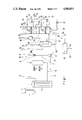
- FIG. 1 is a flow scheme of a plant in which the purified gas is reheated to the required chimney inlet temperature by a heat exchange with the catalytically treated gas.
- FIG. 2 is a flow scheme of a plant in which the purified gas is reheated to the required chimney inlet temperature by a direct heat exchange with dilute sulfuric acid from the SO 3 condenser.
- flue gases from a coal-firing furnace are supplied to the electrostatic precipitator 1, which is operated at a low temperature and collects dust from the flue gas.
- the flue gases contain 2000 mg SO 2 , 800 mg NO x , 50 mg SO 3 , 150 mg HCl, 30 mg HF, 50 g H 2 O.
- the tubular heat exchanger 3 In which they are preheated to 420° C. They are subsequently fed in line 4 to the heater 5, in which fuel oil or fuel gas is burnt by a burner 6 to increase the gas temperature to 450° C.
- the fuel gas which has been heated up is supplied in line 7 to the mixing chamber 8, in which NH 3 from line 9 is admixed to the flue gas.
- the gas is fed to the tower 11, 12 for a DENOX-DESOX catalysis.
- the NO x is reduced with NH 3 to N 2 .
- the SO 2 is oxidized to SO 3 .
- the catalytically treated gas is fed in line 13 to the tubular heat exchanger 3 and is cooled there to 200° C.
- the gas is supplied to the SO 3 condenser 17, which is provided with a distributor plate 18, a sprayer 19 and a mist separator 20.
- the gas is cooled from 120° to 100° C. Water at a rate of 1.2 m 3 /h is fed through line 21 to the SO 3 condenser and is evaporated there.
- the SO 3 condenser 17 60% of the SO 3 contained in the gas are condensed as sulfuric acid and are absorbed.
- the flue gas from which the SO 3 has substantially been removed will flow at a temperature of 100° C. in line 22 to the scrubber 23, which is provided with a distributor plate 24 and a sprayer 25.
- the gas is cooled to 40° C. by an evaporation of water.
- Water at a rate of 3.6 m 3 /h is fed in line 23a to the scrubber 23 and is evaporated there.
- the HCl, HF and traces of SO 2 and SO 3 contained in the gas are substantially scrubbed off by means of acidulated water or a sulfuric acid having a concentration of 5 to 20% by weight.
- H 2 SO 4 mists are separated in a plug filter 26.
- the purified gas is fed via line 27, fan 28 and line 29 to the tubular heat exchanger 15 and is reheated therein to 120° C. and is subsequently delivered in line 30 to the chimney.
- the purified gas contains 130 to 150 mg SO 2 , 30 to 40 mg SO 3 , 50 to 60 mg HCl, 50 to 60 mg NO x (calculated as NO), traces of HF and 90 g H 2 O.
- sulfuric acid having a concentration of 70% by weight H 2 SO 4 is recirculated from the sump of the SO 3 condenser 17 via the line 31, pump 32, line 33 and sprayer 19.
- acidulated water at a temperature of 40° C. is recirculated from the sump of the scrubber 23 via line 34, pump 35, line 36 and sprayer 25.
- acidulated water laden with HCl and HF is fed to a stripping plant, not shown, where the HCl and HF are removed, and the acidulated water is subsequently recycled in line 38 to the SO 3 condenser 17.
- the sulfuric acid formed in the tubular heat exchanger 15 and in the SO 3 condenser 17 at a rate of 7.0 m 3 /day has a concentration of 73.5% by weight H 2 SO 4 and is at a mixed temperature of 110° C.
- H 2 SO 4 is fed in lines 39, 40 and 41 to a single-stage concentrating plant 42, where the concentration is increased to 92% by weight H 2 SO 4 .
- H 2 O 2 from line 43 is admixed to decolorize the product acid.
- a product obtained at a rate of 5.1 m 3 /day and having a concentration of 92% H 2 SO 4 by weight is delivered via line 44.
- the flue gas is supplied at the same rate and temperature and has the came composition as in Example 1 and is preheated to 420° C. in the tubular heat exchanger 3 and is heated up further to 450° C. in an indirect preheater 5 by means of superheated steam from line 6.
- the flue gas is catalytically treated as in Example 1.
- the flue gas which has substantially been catalytically treated is fed at a temperature of 450° C. in line 13 to the tubular heat exchanger 3 and in an indirect heat exchange with the flue gas is cooled to 200° C. In line 14 the gas is fed at a temperature of 200° C.
- the tubular heat exchanger 15 is cooled therein to 157° C., whereby 30% of the SO 3 contained in the flue gas are condensed and removed as sulfuric acid.
- the SO 3 condenser 17 the gas is cooled to 92° C., whereby 70% of the SO 3 contained in the flue gas are condensed and absorbed as sulfuric acid.
- the gas at a temperature of 92° C. enters the scrubber 23 and is cooled therein to 40° C. Sulfuric acid mists are separated in the plug filter 26.
- the gas is fed in line 45 to the direct reheating tower 46, which is provided with a distributor plate 47, a sprayer 48 and a mist separator 49.
- the purified gas is reheated to 105° C. and is then fed to the chimney via line 27a, fan 28 and line 30.
- the purified gas contains 130 to 150 mg SO 2 , 30 to 40 mg SO 3 , 50 to 60 mg HCl, 50 to 60 mg SO 2 , 50 to 60 mg No x (calculated as NO), traces of HF, 78 g H 2 O.
- the cooling of the gas from 92° C. to 40° C. in the scrubber 23 is effected by an evaporation of water. Water at a rate of 2.4 m 3 /h is fed via line 26a to the scrubber 23 and is evaporated therein.
- sulfuric acid having a concentration of 70% by weight H 2 SO 4 is fed at a temperature of 105° C. from the sump of the SO 3 condenser 17 via line 31, pump 32, line 33a to the sprayer 48 in the reheating tower 46. From the reheating tower 46, the acid which has been cooled to 92° C. is recycled via line 50 and the sprayer 19 to the SO 3 condenser and is reheated therein to 105° C.
- acidulated water at a temperature of 40° C. is fed from the sump of the scrubber 23 via line 34, pump 35 and line 36 to the sprayer 25.
- Sulfuric acid which has a concentration of 73% by weight H 2 SO 4 and is at a mixed temperature of 110° C. is obtained in the tubular heat exchanger 15 and the SO 3 condenser 17 at a rate of about 7.0 m 3 /day and via lines 39, 40 and 41 is fed to a concentrating plant 42 and is strengthened therein to a concentration of 92% by weight H 2 SO 4 .
- H 2 O 2 from line 43 is admixed to decolorize the product acid, which has a concentration of 92% by weight H 2 SO 4 and is delivered via line 44 at a rate of 5.1 m 3 /day.
- acidulated water laden with HCl and HF is fed in line 37 to a stripping plant, not shown, in which HCl and HF are removed and from which the acidulated water is recycled in line 38 to the SO 3 condenser 17.
- air at a temperature of 100° C. is fed in line 51 to the tubular heat exchanger 15 and is heated up therein to 160° C. whereas the SO 3 -containing gas is cooled from 200° C. to 157° C.
- the air is recirculated via line 52, fan 53 and feed water preheater 54.
- feed water is fed in line 55 to the feed water preheater and is heated up therein from 40° C. to 95° C. and is delivered in line 56.
- the advantages afforded by the invention reside in that relatively cool flue gases can economically be heated up with a supply of a very small quantity of extraneous energy to the temperature required for the catalytic treatment, sulfuric acid can be recovered from the catalytically treated gases and the gases can be subjected to a fine purification and nevertheless the gases can be reheated without a use of extraneous heat to the minimum temperature required for the admission to the chimney.
Abstract
Description
Claims (11)
Applications Claiming Priority (2)
| Application Number | Priority Date | Filing Date | Title |
|---|---|---|---|
| DE19873744031 DE3744031A1 (en) | 1987-12-24 | 1987-12-24 | METHOD FOR PURIFYING SMOKE GASES |
| DE3744031 | 1987-12-24 |
Publications (1)
| Publication Number | Publication Date |
|---|---|
| US4910011A true US4910011A (en) | 1990-03-20 |
Family
ID=6343555
Family Applications (1)
| Application Number | Title | Priority Date | Filing Date |
|---|---|---|---|
| US07/284,210 Expired - Fee Related US4910011A (en) | 1987-12-24 | 1988-12-14 | Process of purifying flue gases |
Country Status (6)
| Country | Link |
|---|---|
| US (1) | US4910011A (en) |
| EP (1) | EP0322944B1 (en) |
| JP (1) | JPH01203027A (en) |
| AT (1) | ATE81029T1 (en) |
| DE (2) | DE3744031A1 (en) |
| DK (1) | DK170633B1 (en) |
Cited By (18)
| Publication number | Priority date | Publication date | Assignee | Title |
|---|---|---|---|---|
| US5030428A (en) * | 1988-03-26 | 1991-07-09 | Metallgesellschaft Ag | Process of purifying flue gases |
| US5075097A (en) * | 1990-10-11 | 1991-12-24 | Cameron Gordon M | Method and apparatus for sulfuric acid concentration |
| US5094826A (en) * | 1990-01-27 | 1992-03-10 | Gea Luftkuhler Gmbh | Method and arrangement for the denitrification and desulfurization of hot waste gases, particularly from furnaces |
| US5122352A (en) * | 1988-03-08 | 1992-06-16 | Johnson Arthur F | Heat exchanger and pollutant removal system |
| US5230870A (en) * | 1992-05-26 | 1993-07-27 | Johnson Arthur F | Method for converting noxious pollutants from flue gas into merchantable by-products |
| WO1994001190A1 (en) * | 1992-07-10 | 1994-01-20 | Cabot Corporation | Recovery of metal values from process residues |
| US5384106A (en) * | 1991-07-16 | 1995-01-24 | Energy Conservation Partnership Ltd. | Method for removing pollutants from a gas stream using a fractional condensing heat exchanger |
| US5401480A (en) * | 1990-08-14 | 1995-03-28 | Energy Conservation Partnership Ltd. | Removal of sulfur and nitrogen oxides from flue gases |
| WO2007006435A1 (en) * | 2005-07-14 | 2007-01-18 | Outotec Oyj | Process and plant for the condensation of sulfur trioxide from hot starting gases |
| US20080092555A1 (en) * | 2004-05-19 | 2008-04-24 | Egan Gregory J | Cryogenic Container, Superconductivity Magnetic Energy Storage (SMES) System, And Method For Shielding A Cryogenic Fluid |
| GB2474911A (en) * | 2009-10-30 | 2011-05-04 | Goodrich Corp | Metal impurity removal from gaseous stream |
| US20120213690A1 (en) * | 2010-07-08 | 2012-08-23 | Air Products And Chemicals, Inc. | Integration of Catalytic SO2 Oxidation and Oxyfuel Sour Compression |
| WO2012154553A1 (en) * | 2011-05-06 | 2012-11-15 | Fluor Technologies Corporation | Process for chloride reduction |
| GB2510171A (en) * | 2013-01-28 | 2014-07-30 | Cool Flame Technologies As | Oxidising and condensing sulphur and nitrous oxides from exhaust gas |
| CN104941411A (en) * | 2015-05-11 | 2015-09-30 | 武汉都市环保工程技术股份有限公司 | Ozone oxidation and ammonia spraying combined desulfuration and denitration method and device for industrial smoke |
| CN106076102A (en) * | 2016-08-16 | 2016-11-09 | 金川集团股份有限公司 | A kind of process condenses the device and method of nitrogen oxides in acid |
| WO2017071515A1 (en) * | 2015-10-29 | 2017-05-04 | 清华大学 | Device and method enabling industrial coal-fired boiler to concurrently absorb nox and so2 |
| DE102017219401A1 (en) * | 2017-10-27 | 2019-05-02 | Thyssenkrupp Ag | SO3 absorption tower |
Families Citing this family (5)
| Publication number | Priority date | Publication date | Assignee | Title |
|---|---|---|---|---|
| DE4313897C1 (en) * | 1993-04-28 | 1995-03-02 | Degussa | Process for cleaning oxides of nitrogen and sulfur containing flue gases from incineration plants |
| US7176391B2 (en) | 2004-09-13 | 2007-02-13 | Hill-Rom Services, Inc. | Load cell to frame interface for hospital bed |
| DE102007058144A1 (en) | 2007-11-30 | 2009-06-04 | Outotec Oyj | Producing sulfuric acid from a gas containing sulfur dioxide comprises catalytically oxidizing the sulfur dioxide in a converter to obtain sulfur trioxide and absorbing the sulfur trioxide in concentrated sulfuric acid in absorber |
| CN103185346B (en) * | 2013-02-05 | 2015-04-01 | 锐能科技有限公司 | Combined purification system for waste incineration smoke and technology of combined purification system |
| CN109833682A (en) * | 2019-04-19 | 2019-06-04 | 汤辉 | A kind of desulfurization denitration integrative smoke purifying device and its application method |
Citations (5)
| Publication number | Priority date | Publication date | Assignee | Title |
|---|---|---|---|---|
| US3607034A (en) * | 1967-04-05 | 1971-09-21 | Pennsylvania Electric Co | Removal of sulfur dioxide from boiler flue gases |
| US3647360A (en) * | 1970-04-13 | 1972-03-07 | Ovitron Corp | Process for the production of sulfur trioxide by the cold gas process |
| DE3407277A1 (en) * | 1984-02-28 | 1985-08-29 | Deutsche Babcock Anlagen Ag, 4200 Oberhausen | Process and plant for the purification of flue gas |
| DE3514711A1 (en) * | 1985-04-24 | 1986-10-30 | Ferdinand Lentjes, Dampfkessel- und Maschinenbau, 4000 Düsseldorf | Process and apparatus for reheating gas at the cold end of a steam generator |
| DE3601378A1 (en) * | 1986-01-18 | 1987-07-23 | Degussa | METHOD FOR PURIFYING OXIDES OF NITROGEN AND EXHAUST GASES CONTAINING SULFUR FROM COMBUSTION PLANTS |
-
1987
- 1987-12-24 DE DE19873744031 patent/DE3744031A1/en not_active Withdrawn
-
1988
- 1988-12-07 DE DE8888202794T patent/DE3875092D1/en not_active Expired - Lifetime
- 1988-12-07 EP EP88202794A patent/EP0322944B1/en not_active Expired - Lifetime
- 1988-12-07 AT AT88202794T patent/ATE81029T1/en not_active IP Right Cessation
- 1988-12-14 US US07/284,210 patent/US4910011A/en not_active Expired - Fee Related
- 1988-12-23 DK DK721488A patent/DK170633B1/en not_active IP Right Cessation
- 1988-12-24 JP JP63327501A patent/JPH01203027A/en active Pending
Patent Citations (6)
| Publication number | Priority date | Publication date | Assignee | Title |
|---|---|---|---|---|
| US3607034A (en) * | 1967-04-05 | 1971-09-21 | Pennsylvania Electric Co | Removal of sulfur dioxide from boiler flue gases |
| US3647360A (en) * | 1970-04-13 | 1972-03-07 | Ovitron Corp | Process for the production of sulfur trioxide by the cold gas process |
| DE3407277A1 (en) * | 1984-02-28 | 1985-08-29 | Deutsche Babcock Anlagen Ag, 4200 Oberhausen | Process and plant for the purification of flue gas |
| DE3514711A1 (en) * | 1985-04-24 | 1986-10-30 | Ferdinand Lentjes, Dampfkessel- und Maschinenbau, 4000 Düsseldorf | Process and apparatus for reheating gas at the cold end of a steam generator |
| DE3601378A1 (en) * | 1986-01-18 | 1987-07-23 | Degussa | METHOD FOR PURIFYING OXIDES OF NITROGEN AND EXHAUST GASES CONTAINING SULFUR FROM COMBUSTION PLANTS |
| US4744967A (en) * | 1986-01-18 | 1988-05-17 | Degussa Aktiengesellschaft | Process for the purification of exhaust gases containing oxides of nitrogen and sulfur |
Non-Patent Citations (2)
| Title |
|---|
| B.W.K. Brennstoff Warme Kraft, Band 37, No. 9, Sep. 1985, Seiten 77 84, Dusseldorf, DE; B. Scharer et al.: Zur Wirtschaftlichkeit der NOx Abgasreinigung bei Grossfeuerungsanlagen , *FIG. 2b; Seiten 79 80*. * |
| B.W.K. Brennstoff Warme Kraft, Band 37, No. 9, Sep. 1985, Seiten 77-84, Dusseldorf, DE; B. Scharer et al.: "Zur Wirtschaftlichkeit der NOx-Abgasreinigung bei Grossfeuerungsanlagen", *FIG. 2b; Seiten 79-80*. |
Cited By (27)
| Publication number | Priority date | Publication date | Assignee | Title |
|---|---|---|---|---|
| US5122352A (en) * | 1988-03-08 | 1992-06-16 | Johnson Arthur F | Heat exchanger and pollutant removal system |
| US5030428A (en) * | 1988-03-26 | 1991-07-09 | Metallgesellschaft Ag | Process of purifying flue gases |
| US5094826A (en) * | 1990-01-27 | 1992-03-10 | Gea Luftkuhler Gmbh | Method and arrangement for the denitrification and desulfurization of hot waste gases, particularly from furnaces |
| AT399296B (en) * | 1990-01-27 | 1995-04-25 | Gea Luftkuehler Happel Gmbh | METHOD AND DEVICE FOR THE NICKELING AND DESULVERIFYING OF HOT EXHAUST GAS, IN PARTICULAR FROM COMBUSTION |
| US5401480A (en) * | 1990-08-14 | 1995-03-28 | Energy Conservation Partnership Ltd. | Removal of sulfur and nitrogen oxides from flue gases |
| US5075097A (en) * | 1990-10-11 | 1991-12-24 | Cameron Gordon M | Method and apparatus for sulfuric acid concentration |
| US5384106A (en) * | 1991-07-16 | 1995-01-24 | Energy Conservation Partnership Ltd. | Method for removing pollutants from a gas stream using a fractional condensing heat exchanger |
| US5230870A (en) * | 1992-05-26 | 1993-07-27 | Johnson Arthur F | Method for converting noxious pollutants from flue gas into merchantable by-products |
| US5344617A (en) * | 1992-05-26 | 1994-09-06 | Johnson Arthur F | Apparatus for converting noxious pollutants from flue gas into merchantable by-products |
| WO1994001190A1 (en) * | 1992-07-10 | 1994-01-20 | Cabot Corporation | Recovery of metal values from process residues |
| US5437848A (en) * | 1992-07-10 | 1995-08-01 | Cabot Corporation | Recovery of metal values from process residues |
| US20080092555A1 (en) * | 2004-05-19 | 2008-04-24 | Egan Gregory J | Cryogenic Container, Superconductivity Magnetic Energy Storage (SMES) System, And Method For Shielding A Cryogenic Fluid |
| WO2007006435A1 (en) * | 2005-07-14 | 2007-01-18 | Outotec Oyj | Process and plant for the condensation of sulfur trioxide from hot starting gases |
| AU2006268991B2 (en) * | 2005-07-14 | 2010-12-09 | Outotec Oyj | Process and plant for the condensation of sulfur trioxide from hot starting gases |
| US8771623B2 (en) | 2009-10-30 | 2014-07-08 | Goodrich Corporation | Methods and apparatus for residual material management |
| US20110104031A1 (en) * | 2009-10-30 | 2011-05-05 | Goodrich Corporation | Methods and apparatus for residual material management |
| GB2474911A (en) * | 2009-10-30 | 2011-05-04 | Goodrich Corp | Metal impurity removal from gaseous stream |
| GB2474911B (en) * | 2009-10-30 | 2016-01-13 | Goodrich Corp | Methods and apparatus for residual material management |
| US20120213690A1 (en) * | 2010-07-08 | 2012-08-23 | Air Products And Chemicals, Inc. | Integration of Catalytic SO2 Oxidation and Oxyfuel Sour Compression |
| WO2012154553A1 (en) * | 2011-05-06 | 2012-11-15 | Fluor Technologies Corporation | Process for chloride reduction |
| GB2510171A (en) * | 2013-01-28 | 2014-07-30 | Cool Flame Technologies As | Oxidising and condensing sulphur and nitrous oxides from exhaust gas |
| GB2510171B (en) * | 2013-01-28 | 2015-01-28 | Cool Flame Technologies As | Method and cleaning apparatus for removal of SOx and NOx from exhaust gas |
| US9631533B2 (en) | 2013-01-28 | 2017-04-25 | Alfa Laval Aalborg A/S | Method and cleaning apparatus for removal of SOx and NOx from exhaust gas |
| CN104941411A (en) * | 2015-05-11 | 2015-09-30 | 武汉都市环保工程技术股份有限公司 | Ozone oxidation and ammonia spraying combined desulfuration and denitration method and device for industrial smoke |
| WO2017071515A1 (en) * | 2015-10-29 | 2017-05-04 | 清华大学 | Device and method enabling industrial coal-fired boiler to concurrently absorb nox and so2 |
| CN106076102A (en) * | 2016-08-16 | 2016-11-09 | 金川集团股份有限公司 | A kind of process condenses the device and method of nitrogen oxides in acid |
| DE102017219401A1 (en) * | 2017-10-27 | 2019-05-02 | Thyssenkrupp Ag | SO3 absorption tower |
Also Published As
| Publication number | Publication date |
|---|---|
| DE3744031A1 (en) | 1989-07-06 |
| DK721488A (en) | 1989-06-25 |
| EP0322944A1 (en) | 1989-07-05 |
| ATE81029T1 (en) | 1992-10-15 |
| EP0322944B1 (en) | 1992-09-30 |
| DE3875092D1 (en) | 1992-11-05 |
| DK170633B1 (en) | 1995-11-20 |
| DK721488D0 (en) | 1988-12-23 |
| JPH01203027A (en) | 1989-08-15 |
Similar Documents
| Publication | Publication Date | Title |
|---|---|---|
| US4910011A (en) | Process of purifying flue gases | |
| US5030428A (en) | Process of purifying flue gases | |
| CA3159632C (en) | Controlling aerosol production during absorption in ammonia-based desulfurization | |
| US4029751A (en) | Process for producing sulfuric acid | |
| WO2004022205A1 (en) | Method and apparatus for eliminating and recovering s02 from fume | |
| US4842835A (en) | Process of purifying flue gases | |
| US5851265A (en) | Selective removal and recovery of sulfur dioxide from effluent gases using organic phosphorous solvents | |
| CA1053878A (en) | Process for removing contaminants from hot waste gas streams | |
| JP4202451B2 (en) | How to concentrate sulfuric acid | |
| US4001374A (en) | Process for removing ammonia from gases | |
| EP0516001B1 (en) | Process for the regeneration of spent sulphuric acid | |
| US3172725A (en) | Production of sulfuric acid | |
| JPH04228406A (en) | Manufacture of oleum and sulfuric acid | |
| CA1323175C (en) | Process for the purification of exhaust gases | |
| KR20000023700A (en) | Process of producing sulfuric acid | |
| GB2153806A (en) | A method of producing sulphuric acid from sulphur dioxide and apparatus therefor | |
| JPH06319955A (en) | Method of cleaning flue gas containing nitrogen and sulfur oxide from combustion equipment | |
| DE3573466D1 (en) | Process and device for reheating flue gases | |
| CN107438476B (en) | Continuous process and apparatus for purifying SO 2-containing gas | |
| US4834954A (en) | Process for cleaning flue gases | |
| NO306772B1 (en) | Process for recovery of sulfuric acid | |
| CN211384472U (en) | Novel medium-low temperature two-stage drying system in burner gas | |
| US3950502A (en) | Process for working up the scrubbing solution obtained in the scrubbing of So2 -containing waste gases | |
| CA1293359C (en) | Process for removing oxides of nitrogen and sulfur from waste gases | |
| KR20230142786A (en) | Dilute sulfuric acid production device and dilute sulfuric acid production method |
Legal Events
| Date | Code | Title | Description |
|---|---|---|---|
| AS | Assignment |
Owner name: STADTWERKE MUNSTER GMBH, ALBERSLOHER WEG 27-31 D-4 Free format text: ASSIGNMENT OF ASSIGNORS INTEREST.;ASSIGNORS:DORR, KARL-HEINZ;GRIMM, HUGO;NEUMANN, HEINZ;AND OTHERS;REEL/FRAME:004986/0563 Effective date: 19881202 Owner name: STADTWERKE MUNSTER GMBH, A GERMAN CORP., GERMANY Free format text: ASSIGNMENT OF ASSIGNORS INTEREST;ASSIGNORS:DORR, KARL-HEINZ;GRIMM, HUGO;NEUMANN, HEINZ;AND OTHERS;REEL/FRAME:004986/0563 Effective date: 19881202 |
|
| FEPP | Fee payment procedure |
Free format text: PAYOR NUMBER ASSIGNED (ORIGINAL EVENT CODE: ASPN); ENTITY STATUS OF PATENT OWNER: LARGE ENTITY |
|
| FEPP | Fee payment procedure |
Free format text: PAYOR NUMBER ASSIGNED (ORIGINAL EVENT CODE: ASPN); ENTITY STATUS OF PATENT OWNER: LARGE ENTITY Free format text: PAYER NUMBER DE-ASSIGNED (ORIGINAL EVENT CODE: RMPN); ENTITY STATUS OF PATENT OWNER: LARGE ENTITY |
|
| CC | Certificate of correction | ||
| FPAY | Fee payment |
Year of fee payment: 4 |
|
| FEPP | Fee payment procedure |
Free format text: PAYER NUMBER DE-ASSIGNED (ORIGINAL EVENT CODE: RMPN); ENTITY STATUS OF PATENT OWNER: LARGE ENTITY Free format text: PAYOR NUMBER ASSIGNED (ORIGINAL EVENT CODE: ASPN); ENTITY STATUS OF PATENT OWNER: LARGE ENTITY |
|
| REMI | Maintenance fee reminder mailed | ||
| LAPS | Lapse for failure to pay maintenance fees | ||
| FP | Lapsed due to failure to pay maintenance fee |
Effective date: 19980325 |
|
| STCH | Information on status: patent discontinuation |
Free format text: PATENT EXPIRED DUE TO NONPAYMENT OF MAINTENANCE FEES UNDER 37 CFR 1.362 |