US4911501A - Suspension mechanism for connecting chair backs and seats to a pedestal - Google Patents
Suspension mechanism for connecting chair backs and seats to a pedestal Download PDFInfo
- Publication number
- US4911501A US4911501A US07/364,996 US36499689A US4911501A US 4911501 A US4911501 A US 4911501A US 36499689 A US36499689 A US 36499689A US 4911501 A US4911501 A US 4911501A
- Authority
- US
- United States
- Prior art keywords
- spring
- stanchion
- suspension mechanism
- seating portion
- lock bar
- Prior art date
- Legal status (The legal status is an assumption and is not a legal conclusion. Google has not performed a legal analysis and makes no representation as to the accuracy of the status listed.)
- Expired - Fee Related
Links
Images


Classifications
-
- A—HUMAN NECESSITIES
- A47—FURNITURE; DOMESTIC ARTICLES OR APPLIANCES; COFFEE MILLS; SPICE MILLS; SUCTION CLEANERS IN GENERAL
- A47C—CHAIRS; SOFAS; BEDS
- A47C31/00—Details or accessories for chairs, beds, or the like, not provided for in other groups of this subclass, e.g. upholstery fasteners, mattress protectors, stretching devices for mattress nets
- A47C31/12—Means, e.g. measuring means for adapting chairs, beds or mattresses to the shape or weight of persons
- A47C31/126—Means, e.g. measuring means for adapting chairs, beds or mattresses to the shape or weight of persons for chairs
-
- A—HUMAN NECESSITIES
- A47—FURNITURE; DOMESTIC ARTICLES OR APPLIANCES; COFFEE MILLS; SPICE MILLS; SUCTION CLEANERS IN GENERAL
- A47C—CHAIRS; SOFAS; BEDS
- A47C1/00—Chairs adapted for special purposes
- A47C1/02—Reclining or easy chairs
- A47C1/031—Reclining or easy chairs having coupled concurrently adjustable supporting parts
- A47C1/032—Reclining or easy chairs having coupled concurrently adjustable supporting parts the parts being movably-coupled seat and back-rest
- A47C1/03255—Reclining or easy chairs having coupled concurrently adjustable supporting parts the parts being movably-coupled seat and back-rest with a central column, e.g. rocking office chairs
-
- A—HUMAN NECESSITIES
- A47—FURNITURE; DOMESTIC ARTICLES OR APPLIANCES; COFFEE MILLS; SPICE MILLS; SUCTION CLEANERS IN GENERAL
- A47C—CHAIRS; SOFAS; BEDS
- A47C1/00—Chairs adapted for special purposes
- A47C1/02—Reclining or easy chairs
- A47C1/031—Reclining or easy chairs having coupled concurrently adjustable supporting parts
- A47C1/032—Reclining or easy chairs having coupled concurrently adjustable supporting parts the parts being movably-coupled seat and back-rest
- A47C1/03261—Reclining or easy chairs having coupled concurrently adjustable supporting parts the parts being movably-coupled seat and back-rest characterised by elastic means
- A47C1/03277—Reclining or easy chairs having coupled concurrently adjustable supporting parts the parts being movably-coupled seat and back-rest characterised by elastic means with bar or leaf springs
-
- A—HUMAN NECESSITIES
- A47—FURNITURE; DOMESTIC ARTICLES OR APPLIANCES; COFFEE MILLS; SPICE MILLS; SUCTION CLEANERS IN GENERAL
- A47C—CHAIRS; SOFAS; BEDS
- A47C3/00—Chairs characterised by structural features; Chairs or stools with rotatable or vertically-adjustable seats
- A47C3/02—Rocking chairs
- A47C3/025—Rocking chairs with seat, or seat and back-rest unit elastically or pivotally mounted in a rigid base frame
- A47C3/0252—Rocking chairs with seat, or seat and back-rest unit elastically or pivotally mounted in a rigid base frame connected only by an elastic member positioned between seat and base frame
-
- A—HUMAN NECESSITIES
- A47—FURNITURE; DOMESTIC ARTICLES OR APPLIANCES; COFFEE MILLS; SPICE MILLS; SUCTION CLEANERS IN GENERAL
- A47C—CHAIRS; SOFAS; BEDS
- A47C7/00—Parts, details, or accessories of chairs or stools
- A47C7/36—Support for the head or the back
- A47C7/40—Support for the head or the back for the back
- A47C7/44—Support for the head or the back for the back with elastically-mounted back-rest or backrest-seat unit in the base frame
- A47C7/445—Support for the head or the back for the back with elastically-mounted back-rest or backrest-seat unit in the base frame with bar or leaf springs
Definitions
- the present invention relates generally to chair constructions. More particularly, the present invention relates to a suspension mechanism for adjustably connecting the seating portion and the back supporting portion of an office chair to a pedestal. Specifically, the present invention relates to a suspension mechanism which permits not only selectively independent movement of the seating portion and/or the back supporting portion of a chair but also combined movement of the seating and back supporting portions, without any restrictive requirement for synchronization therebetween.
- the prior art is replete with structural arrangements for connecting seating portions and back supporting portions to pedestal assemblies.
- the seating portion of an office chair was fixedly secured to the upper end portion of a pedestal assembly.
- the back supporting portion was sometimes also rigidly secured to the pedestal assembly, and sometimes the back supporting portion was permitted to swing rearwardly, to at least some predetermined degree, in order to permit the person seated in the chair to lean back against the resistance of a biasing mechanism incorporated between the back supporting portion and either the pedestal assembly or the seating portion.
- the seating portion was generally mounted on pivot axles presented from the pedestal assembly, with variously adjustable spring means being utilized to provide the desired resistance to the tilting action of the seating portion.
- the back supporting portion was initially disposed to be fixed in relation to the seating portion. As the construction of office chairs was refined, the back supporting portion was permitted to swing with respect to the seating portion, but generally only in synchronized relation to the tilting movement of the seating portion.
- the back supporting portion was permitted to be swung only a given number of degrees in relation to the number of degrees through which the seating portion was tilted.
- the back support would generally swing through a range that was mathematically fixed in relation to the number of degrees through which the seating portion was being tilted.
- the axis about which the back supporting portion was permitted to swing was generally located in proximity to the rear of the seating portion.
- the back supporting portion would "scrub" against the clothing being worn by the person seated in the chair.
- this scrubbing action was not serious, during the course of several hours the shirt, or blouse, being worn by the person using the chair could be extricated from a mere frictional support at the waist.
- a suspension mechanism embodying the concepts of the present invention is utilized to interconnect the seating portion as well as the back supporting portion of a chair to a pedestal assembly.
- a spring support is secured to the upper end portion of the pedestal assembly.
- Virtually any pedestal assembly can be employed in conjunction with the present invention inasmuch as the structure of the pedestal assembly is not in the least critical to the present invention.
- At least one primary seat spring is secured to the spring support and extends generally upwardly and rearwardly therefrom to be secured to the underside of the seating portion.
- the primary seat spring comprises a pair of laterally spaced, leaf springs.
- an interactive spring Also secured to the spring support, and preferably between the pair of laterally spaced primary seat springs, is an interactive spring.
- the interactive spring extends outwardly from the spring support in generally parallel relation with the primary seat springs to be disposed in a cantilevered fashion.
- the back supporting portion includes a back cushion that is pivotally mounted on a structural stanchion which is, in turn, pivotally supported from the seating portion of the chair assembly.
- a follower means is presented from the stanchion operatively to engage the interactive spring.
- a main back supporting spring is secured to the stanchion to interact in relation to the seating portion.
- FIG. 1 is a perspective view of a chair embodying the concepts of the present invention
- FIG. 2 is frontal elevation of the chair depicted in FIG. 1;
- FIG. 3 is a schematic side elevation taken substantially along line 3--3 of FIG. 2;
- FIG. 4 is a horizontal section taken substantially along line 4--4 of FIG. 3 and depicting the seating portion of the chair in bottom plan;
- FIG. 5 is a vertical section taken substantially along line 5--5 of FIG. 2 to depict the main seat spring that is connected between the spring support and the pan of the seating portion in the chair depicted in FIGS. 1 and 2 as well as that lock-out assembly which is operative between the seating portion and the spring support;
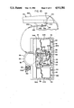
- FIG. 6 is a vertical section taken substantially along line 6--6 of FIG. 2 to depict not only the interactive spring that is cantilevered outwardly from the spring support to be operatively engaged by the back supporting portion but also the main back support spring that is secured to the back supporting portion operatively to engage the pan of the seating portion as well as that lock-out assembly which is operative between the seating portion and the stanchion;
- FIG. 7 is a schematic side elevation, similar to FIG. 3 but depicting the chair with both the seating portion having been tilted and the back supporting portion having been swung with respect to the pedestal assembly, the relative position of the back supporting portion with respect to the seating portion remaining substantially the same as that relationship is represented in FIG. 3;
- FIG. 8 is a schematic side elevation similar to FIGS. 3 and 7, but depicting the chair with only the back supporting portion having been tilted with respect to the seating portion, the seating portion remaining fixedly disposed relative to the pedestal assembly;
- FIG. 9 is a schematic side elevation, more closely similar to FIG. 7, with both the seating portion having been tilted and the back supporting portion having been swung with respect to the pedestal assembly, but with the back supporting portion having been swung through a significantly greater angular displacement than the angular displacement through which the seating portion has been tilted;
- FIG. 10 is an enlarged, side elevation of the back cushion, partly broken away to reveal the interconnection of the cushion with the stanchion;
- FIG. 11 is an enlarged cross section taken substantially along line 11--11 of FIG. 4 to depict the journal arrangement by which the back supporting portion may be pivotally carried on the seating portion, FIG. 11 appearing on the same sheet of drawings as FIG. 4;
- FIG. 12 is a schematic representation of a representative lock-out assembly, with the housing thereof being depicted in horizontal section;
- FIG. 13 is a vertical section taken substantially along line 13--13 of FIG. 12;
- FIG. 14 is a side elevation of the housing depicted in FIGS. 12 and 13; and,
- FIG. 15 is a schematic representation of a structural arrangement by which to effect translation of the movable wedge member associated with the interactive spring, the spring support being shown in top plan to reveal the incorporation of the lock-out assembly as it is secured to the spring support, the spring support also being partly broken away more precisely to reveal the mechanism by which the control lever effects translation of the wedge member.
- the representative suspension mechanism 10 is incorporated in a chair assembly 12, and as seen in FIG. 1, the chair assembly 12 comprises a pedestal assembly 14, a seating portion 16 and a back supporting portion 18.
- the suspension mechanism 10 is the sole structure interposed between the pedestal assembly 14 and both the seating portion 16 and the back supporting portion 18.
- the pedestal assembly 14 has a conventional, five leg spider, or base, 20 with a caster wheel 22 secured at the outer end of each leg 24 on the spider 20.
- the five legged spider 20 provides stability for the chair assembly 12 when the occupant is moving the chair while seated, or while leaning forwardly, rearwardly, or to the side. These movements are often made when the occupant desires to retrieve an article without leaving the chair.
- the pedestal assembly 14 also includes a cylindrical post 26 on which a spring support 30 is secured, as by the cylindrical mounting cup 32 which circumscribes the post 26.
- the spring support 30 has a pair of laterally spaced, spring engaging ramps 34, the upwardly facing surface 36 of which is curvilinearly contoured, as depicted in FIGS. 3 and 5.
- Each curvilinearly contoured surface 36 merges into an anchor surface 38.
- the anchor surfaces 38A and 38B are adjacent the ramps 34A and 34B.
- a particular structural member, component or arrangement may be employed at more than one location.
- a common numerical designation shall be employed.
- one of the structural members, components or arrangements so identified is to be individually identified it shall be referenced by virtue of a letter suffix employed in combination with the numerical designation employed for general identification of that structural member, component or arrangement.
- a primary seat spring 40 is secured to each of the laterally spaced anchor surfaces 38.
- individual mounting plates 42 and threaded fasteners 44 may be employed.
- a mounting plate 42 is disposed to overlie the first end portion 46 of each primary seat spring 40 so the fasteners 44 may pass through appropriate openings in each mounting plate 42 as well as through openings in the first end portion 46 of each primary seat spring 40 and finally into receiving bores 48 in the laterally spaced anchor surfaces 38A and 38B.
- the primary seat springs 40 are, therefore, securely anchored to the spring support 30, and thereby to the pedestal assembly 14.
- a central slideway, or recess, 50 houses a movable wedge member 52.
- the upwardly facing surface 54 on the movable wedge member 52 is also curvilinearly contoured and may be juxtaposed to a centrally located spring anchor surface 56 which is also presented from the spring support 30.
- An interactive spring 60 is centrally positioned on the spring support 30 intermediately with respect to the primary seat springs 40A and 40B.
- the interactive spring 60 is attached to the spring support 30 in a manner similar to that used for the attachment on the primary seat springs 40. That is, a mounting plate 42 is disposed to overlie the first end portion 64 of the interactive spring 60, and a pair of threaded fasteners 44 are inserted through appropriate openings provided in the mounting plate 42, through registered bores in the first end portion 64 of the interactive spring 60 and into receiving bores 66 in the central anchor surface 56.
- each of the primary seat springs 40 When properly secured to the anchor surfaces 38, each of the primary seat springs 40 are vertically aligned with one of the curvilinearly contoured surfaces 36 on the ramps 34. So aligned, the primary seat springs 40 extend generally rearwardly and upwardly from the respective, laterally spaced anchor surfaces 38.
- the interactive spring 60 which is located between the laterally spaced primary seat springs 40, is vertically aligned with the central slideway 50 on the spring support 30.
- the interactive spring 60 extends generally rearwardly and upwardly from the central anchor surface 56.
- the interactive spring 60 is purposely shorter than the primary seat springs 40, and as such the interactive spring 60 is cantilevered outwardly from the central anchor surface 56 to which the first end portion 64 of the interactive spring 60 is secured. As such, the second end portion 68 of the interactive spring 60 is unsupported.
- each primary seat spring 40A and 40B is connected to the seat pan 72 in the seating portion 16 of the chair assembly 12 at anchor surfaces 74A and 74B which align with the lateral anchor surfaces 38A and 38B, respectively, on the spring support 30.
- Each anchor surface 74 is substantially flat and is provided with a pair of receiving bores 76.
- the second end portion 70 of each primary seat spring 40 is secured to one of the anchor surfaces 74 by a flat, mounting plate 42 and a pair of preferably threaded fasteners 44 which extend through the mounting plate 42, the second end portion 70 of the respective, primary seat springs 40 and into the receiving bores 76 in the same manner as the end portions of the other spring members have heretofore been described as being secured to their respective anchor surfaces.
- the seat pan 72 has a pair of mounting blocks 80 each having a bearing surface in the configuration of a semi-cylindrical saddle 82.
- the seat pan 72 is mounted on a pair of laterally spaced, cylindrical journals 84 formed integrally with the base portion 86 of a stanchion 90.
- a cap 92 having an opposed, semi-cylindrical, bearing surface 94 is secured to each mounting block 80 with one of the journals 84 disposed between the opposed bearing surfaces 82 and 94.
- a pair of fasteners 96 may be employed to secure each cap 92 to its respective mounting block 80.
- the journals 84 thus define the pivotal axis about which the stanchion 90 will swing in relation to the seating portion 16.
- FIG. 3 represents the fore and aft location of the journals 84 to be medially between the fore and aft boundary delineated by the connection of the primary seat spring 40 with the spring support 30 and the connection of the primary seat spring 40 with the seating portion 16. This location accomplishes the desired result of allowing the back supporting portion 18 to swing back and forth about virtually the same center of rotation as the person seated on the seating portion 16.
- the substantial concentricity for the swinging movement of the back supporting portion 18 and leaning movement of the person using the chair assembly 12 obviates the undesirable scrubbing action historically present between the back supporting portion 18 and the user when the seating portion and the back supporting portion of the chair were both capable of being moved.
- the journals 84 are located approximately one-third the distance from the front of the seating portion 16 to the rear thereof.
- the stanchion 90 has a pair of S-curved support arms 98A and 98B which are laterally spaced to lie on either side of the seating portion 16 and which extend between the base portion 86 of the stanchion 90 to a transverse support bar 100, also comprising an integral portion of the stanchion 90.
- the base portion 86, the support arms 98 as well as the transverse support bar 100 thus combine to form the stanchion 90 of the back supporting portion 18 in the chair assembly 12.
- a back cushion assembly 102 may be pivotally secured to the transverse support bar 100 by a pivot joint 104 that may be hidden within the back cushion assembly 102.
- a pair of spacer arms 106 are offset from the transverse support bar 100 and extend upwardly, terminating in opposed stub shafts 108, The stub shafts 108 are disposed to lie adjacent to the frame plate 110 of the back cushion assembly 102.
- a cushion 114 is attached to the frame plate 110 by means well known to the art.
- a pair of opposed fingers 112A and 112B may be struck from the frame plate 110 to embrace the stub shafts 108 and permit the latter to rotate therebetween, at least through that number of degrees which affords comfortable engagement of the cushion 114 with a person sitting in the chair assembly 12.
- a decorative backing panel 116 may be secured to the frame plate 110 by snaps 117, and a pair of guard arms 118 extend outwardly from the decorative backing panel 116 to embrace the fingers 112 and thereby assist in maintaining the desired engagement between the fingers 112 and the stub shafts 108.
- the back cushion assembly 102 is thus capable of at least a limited degree of rotation about the transverse, rotational axis 120 of the pivot joint 104 in order to accommodate the back of the person seated in the chair assembly 12.
- the base portion 86 of the stanchion 90 has a pair of lever arms 122A and 122B that are disposed laterally of the sagittal plane 124 with respect to the chair assembly 12.
- the outer end portion of each lever arm 122 terminates in a hook 126 that is adapted to receive a rod-like axle 128 upon which a low friction follower, or drive wheel, 130 is rotatably mounted.
- the follower 130 is preferably aligned with the sagittal plane 124 of the chair assembly 12, as seen in FIG. 6.
- the follower 130 preferably rests lightly against the interactive spring 60 when the chair assembly 12 is in the "at rest," or unoccupied, position depicted in FIG. 3.
- the base portion 86 of the stanchion 90 also presents a curvilinearly contoured surface 132 which merges with an anchor surface 134.
- the first end 136 of a primary back spring 140 is attached to the anchor surface 134 in a manner similar to that used for the primary seat spring 40 as well as the interactive springs 60. That is, a mounting plate 42 overlies the first end 136 of the primary back spring 140, and a pair of fasteners 44 penetrate the mounting plate 42 and the first end 136 of the primary back spring 140 threadably to engage receiving bores 142 in the anchor surface 134.
- the second end 144 of the primary back spring 140 is disposed in sliding engagement with the undersurface 146 of the seat pan 72.
- the primary seat springs 40, the interactive spring 60 and the primary back spring 140 are all preferably of the leaf spring variety. Although one may fabricate the aforesaid leaf springs from any desired material, it has been found that fiber reinforced plastic or carbon composite material works extremely well.
- the primary seat springs 40 and the interactive spring 60 are laterally aligned. Particularly when the chair assembly 12 is empty, there is virtually no stress imparted to the primary seat springs 40 or the interactive spring 60. Similarly, the primary back spring 140 is also only slightly stressed under the virtually no load condition. As such, the primary seat springs 40 are only barely in contact with the curvilinearly contoured surfaces 36 on the spring support 30, and the primary back spring 140 is barely in contact with the curvilinearly contoured surface 132.
- the primary seat springs 40 deflect under the weight of the person sitting on the seating portion 16.
- the weight of the person sitting in the chair will determine the extent to which the primary seat springs 40 will engge the curvilinearly contoured surfaces 36 on the spring support 30.
- the flexure characteristics of the primary seat springs 40 are directly affected by the extent to which the primary seat springs 40 engage the curvilinearly contoured surfaces 36. The greater the distance along the surfaces 36 that is contacted by the springs 40, the stiffer the springs 40 appear to be. Thus, if a relatively heavy person is seated in the chair, the weight of that person will establish flexure characteristics for the springs 40 which directly reflect the heavier weight of the person using the chair.
- a chair assembly 12 incorporating a suspension mechanism 10 embodying the concepts of the present invention is equally acceptable for use by virtually any size person.
- the occupant of the chair 12 wishes to tilt the seating portion 16 rearwardly (while maintaining the existing angularity between the back supporting portion 18 and the seating portion 16).
- the occupant need merely shift his, or her, weight rearwardly on the seating portion 16.
- the primary seat springs 40 will further deflect counterclockwise about the anchor surfaces 38, as seen in FIG. 7.
- the primary seat springs 40 will come into increasing contact with the length of the curvilinearly contoured surfaces 36. Therefore, as the seat pan 72 is tilted, the resistance to further tilting will increase.
- the interactive spring 60 will be deflected by the generally downward movement of the stanchion 90 as it is carried with the seating portion 16.
- This downward movement of the stanchion 90 forces the follower 130 against the interactive spring 60.
- Engagement of the follower 130 with the interactive spring 60 flexes the interactive spring 60 and brings the interactive spring 60 into progressively increasing engagement with the curvilinear surface 54 on the movable wedge member 52.
- the wedge member 52 is movable, one can adjust the flexure characteristics of the interactive spring 60 by selectively positioning the wedge member 52 within the slideway 50 to control the amount of deflection required by the interactive spring 60 before it will engage the curvilinearly contoured surface 54 on the wedge member 52.
- This simple predisposition of the wedge member 52 offers a relatively easy way in which to adjust the stiffness of the chair 12 in response to the particular person who will use it.
- the second end 144 of the primary back spring 140 will not only slide along the undersurface 146 of the seat pan 72 but the action of the second end 144 of the primary back spring 140 against the undersurface 146 of the seat pan 72 will cause the primary back spring 140 to flex, thereby progressively engaging the curvilinearly contoured surface 132 and thus also progressively stiffening the flexure characteristics of the primary back spring 140 which imparts resistance to the rearward swinging movement of the back supporting portion 18.
- This rearward swinging movement of the back supporting portion 18 also forces the follower 130 to engage, and flex, the interactive spring 60.
- the interactive spring 60 also supplies an additional biasing force which tends to resist the rearward swinging movement of the back supporting portion 18.
- the person occupying the chair 12 will desire not only to tilt the seating portion 16 rearwardly but simultaneously also to swing the back supporting 18 rearwardly, as seen in FIG. 9.
- the tilting of the seating portion 16 will also cause the follower 130 to engage, and flex, the interactive spring 60 in the same manner heretofore described in conjunction with the explanation as to the action of the primary seat springs 40 and the interactive spring 60 when the seating portion 16 is tilted.
- a chair embodying the concepts of the present invention may secure the chair so that only the seating portion 16 will tilt or so that only the back supporting portion 18 will swing, as desired.
- Such a response may be obtained by the use of a pair of lock-out assemblies 150, a representative example of which is depicted in FIGS. 6 and 12 through 14.
- the lock-out assembly 150 utilizes a lock bar 152 which reciprocates within a housing 154 that contains the lock and release mechanism 156.
- the exemplary lock bar 152 depicted employs a semi-cylindrical shaft portion 158 which presents a plurality of teeth 160 that extend axially along the outer surface of the shaft portion 158.
- a pair of shoulders 162A and 162B extend radially outwardly on diametrically opposite sides of the shaft portion 158.
- the housing 154 of the lock-out assembly has a support plate 164 from which a locking block 166 is supported. Specifically, a mounting bolt 168 passes through the support plate 164 and is received within a bore 170 in the reverse face 172 of the locking block 166. The mounting bolt 168 is tightened sufficiently to secure the locking block 166 to the support plate 164 but is loose enough to permit the locking block 166 to adjust to the modest difference between the angularity of the lock bar 152 as it swings between the engaged and the disengaged positions. To understand the engaged and the disengaged positions it must be noted that the locking block 166 has a recess 174 in the obverse face 176 thereof.
- the semi-cylindrical inner surface of the recess 174 presents a plurality of teeth 178 which are adapted matingly to engage the teeth 160 on the shaft portion 158 of the lock bar 152.
- the movement of the locking block 166 is necessary to accommodate full engagement of the teeth 178 in the semi-cylindrical recess 174 of the locking block 166 with the teeth 160 on the lock bar 152.
- Engagement, and disengagement, of the teeth 160 and 178 can be enhanced by making the reverse face 172 of the locking block 166 arcuate about an axis disposed transversely of the recess 174, as best seen in FIG. 12.
- the combination of the arcuate, reverse face 172 and the modestly loose engagement of the mounting bolt 168 permit the desired accommodation of the teeth 178 in the locking block 166 to the teeth 160 on the lock bar 152.
- Spring means are employed to bias the teeth 160 on the lock bar 152 out of engagement with the teeth 178 on the locking block 166.
- a pair of release springs 180A and 180B may be secured to the support plate 164 and engage the opposed shoulders 162A and 162B, respectively, to bias the lock bar 152 away from the locking block 166.
- An actuating throw arm 182 is pivotally mounted within the housing 154. Specifically, a pair of stub shafts 184A and 184B extend outwardly from the opposite sides of the actuating throw arm 182 to be journaled within the laterally spaced, side walls 186 and 188 of the housing 154. A cam surface 190 on the actuating throw arm 182 engages the spine surface 192 on the lock bar 152. As such, rotation of the actuating throw arm 182 (clockwise as seen in FIG. 13) drives the cam surface 190 against the spine surface 192 on the lock bar 152 to drive the teeth 160 on the lock bar 152 against the teeth 178 in the recess 174 of the locking block 166.
- a cable 194 is secured to the transverse end surface 196 of the stub shaft 184B so that rotation of the cable 194 will effect rotation of the actuating throw arm 182.
- the opposite end of the cable 194 is secured to a control lever 200 which may be journaled for rotation in the support arm 98A of the stanchion.
- the control lever 200 can be located in proximity to the juncture of the base portion 86 with the support arm 98A. At this point it should be noted that the control lever 200 may well be preferred to be presented from support arm 98A.
- the control lever 200, and/or the other controls hereinafter described, can be located on whatever side, or sides, of the chair assembly 12 one might prefer--their location does not affect their operation.
- the control lever 200 engages first and second detents 202 and 204, respectively, which define the extent to which the control lever 200 can be rotated.
- first and second detents 202 and 204 respectively, which define the extent to which the control lever 200 can be rotated.
- the rotational force applied to the control lever 200 is transferred through the cable 194 to rotate the actuating throw arm 182.
- the throw arm 182 will secure the lock bar 152 in the proper position with respect to the locking block 166.
- Engagement of the control lever 200 with the first detent 202 may well be sufficient to maintain the actuating throw arm 182 in the desired position, however, it is possible to configure the cam surface 190 so that it will assume an over-the-center locking engagement with the spine surface 192 on the lock bar 152.
- the cable 194 is capable of storing the energy created by the rotational force applied to the control lever 200 until some relative movement between the lock bar 152 and the locking block 166 occurs which will effect a meshing alignment of the teeth 160 and 178. At that time the stored energy in the cable 194 will complete the rotation of the actuating throw arm 182 and effect the desired locking of the lock bar 152 against the locking block 166.
- control lever 200 when one wishes to release the lock-out assembly 150 the control lever 200 is rotated to release it from engagement with the first detent 202 and bring it into operative engagement with the second detent 204. Such rotation is transferred through the cable 194 the counter-rotate the actuating throw arm 182 and allow the release springs 180 to bias the lock bar 152 away from the locking block 166, thus disengaging the teeth 160 from the teeth 178.
- the afore-described lock-out assembly 150 can be used not only to effect selective immobilization of the back supporting portion 18 in relation to the seating portion 16 but also to effect selective immobilization of the seating portion 16 with respect to the pedestal assembly 14, or, if desired, simultaneously to immobilize both movements.
- the lock bar 152 is secured to the seat pan 72, and the housing 154 is secured to, or incorporated in, the base portion 86 of the stanchion 90, as depicted by lock-out assembly 150A in FIG. 6.
- lock bar 152 is also secured to the seat pan 72, but the housing 154 is secured to, or incorporated in, the spring support 30.
- This arrangement is represented by lock-out assembly 150B in FIG. 6 wherein the housing 154 is incorporated along the exterior surface of the cylindrical mounting cup 32.
- the wedge member 52 is movable within the slideway 50 in order to adjust the flexure characteristics of the interactive spring 60.
- the movable wedge member 52 is depicted at end 206 of the slideway 50.
- the interactive spring 60 has the lightest pre-load and the lowest spring rate.
- the interactive spring 60 provides the least resistance to movement of the seating portion 16 or the back supporting portion 18.
- the wedge member 52 is moved toward the end 208--the opposite end of the slideway 50--the spring rate of the interactive spring 60 will increase. Therefore, if increased resistance is desired for a given angular range of movement for the back supporting portion 18, the wedge member 52 is moved toward end 208 of the slideway 50.
- the flexure characteristics of the interactive spring 60 contribute to the basic stiffness of the chair assembly 12 inasmuch as the follower 130 applies some pressure to the interactive spring 60 when a relatively heavy person sits on, or attempts to tilt, the seating portion 16 or swing the back supporting portion 18.
- the movement of the wedge member 52 required to achieve the desired flexure characteristics of the interactive spring 60 can also be effected by manual operation of a control lever 210 that may, for convenience, be located in support arm 98B of the stanchion 90, as shown, or, if desired, the control lever 210 may be located in proximity to the control levers 200.
- the control lever 210 is mounted on a pivot pin 212 with the effort arm 214 extending outwardly from the pivot pin 212 to be available for manipulation by the person who is adjusting the chair assembly 12.
- the diametrically opposed resistance arm 216 extends inwardly from the pivot pin 212, and thus inwardly relative to the support arm 98B of the stanchion 90.
- the end of the resistance arm 216 is secured, by means well known to the art, to a core 218 that is slidably received within the sheath 220 of a push pull control cable 222.
- That end of the sheath 220 adjacent the resistance arm 216 is secured to the stanchion 90, as by a first mounting bracket 224.
- the opposite end of the sheath 220 is secured to the spring support 30, as by a second mounting bracket 226.
- the spring arm 228 is mounted on a pivot 230 presented from the spring support 30 and extends from the pivot 230 to be swingingly received in a recess 232 incised in the undersurface 234 of the wedge member 52--the curvilinearly contoured surface 54 being presented from the opposite side of the wedge member 52.
- the weight on the seating portion 16 could be sufficient for the follower 130 to have forced the interactive spring 60 against the curvilinearly contoured surface 54 on the wedge member 52, thus precluding translation of the wedge member 52.
- the spring arm 228 By making the spring arm 228 from a material that will flex, the operator will immediately notice that the control lever 210 will not remain in the position selected, but will, instead, simply return to the position it had been in when the adjustment was begun. As such, a tactile signal is provided by the structural configuration described. The unspoken message is that the wedge member 52 cannot be moved until the interactive spring 60 is unloaded.
- the control lever 210 is rotated in the opposite direction (counterclockwise as viewed in FIG. 15) to pull the core 218.
- pulling on the core 218 effects clockwise movement of the spring arm 228 against the wall 238 of the recess 232, and thereby urges the wedge member 52 toward the second end 208 of the slideway 50.
- This location of the wedge member 52 delays engagement of the interactive spring 60 with the curvilinearly contoured surface 54 on the wedge member 52 to decrease the stiffness of the interactive spring 60.
- the control lever 210 will provide a tactile signal if the wedge member 52 is locked such that it cannot be translated within the slideway 50.
- the primary seat springs 40 which connect the seating portion 16 to the spring support 30, serve the purpose of supporting the seating portion 16.
- the primary seat springs 40 also allow the seating portion 16 to tilt rearwardly, to provide that desired feature of many conventional chairs.
- the primary seat springs 40 further allow the seating portion 16 to tilt forwardly, a feature provided by the newer style "task chairs.” The “at rest” position between these ranges of movement is most appropriate for entry and egress. It should also be noted that no pivot axles are required to support the seating portion 16, thus reducing friction and the potential for wear and squeaking.
- the interactive spring 60 which is preferably mounted from the spring support 30, provides additional biasing force when the seating portion 16 is tilted rearwardly.
- the interactive spring 60 also supplies additional biasing force when the back supporting portion 18 is swung rearwardly, as previously discussed.
- the biasing effect is compounded. This compounding is desirable because the load on the back supporting portion 18 increases as the seating portion 16 is tilted rearwardly. The rearward tilt if the seating portion 16 allows the torso of the person in the chair 12 to move further rearwardly with respect to the center line of the pedestal assembly 14.
- curvilinearly contoured surfaces provides the desired change in the flexure characteristics of the springs when a heavy person sits in the chair. As the springs deflect downwardly the curvilinearly contoured surfaces are designed progressively to shorten the effective length of the springs. On the other hand, a light person does not deflect the springs sufficiently to effect engagement between the springs and the curvilinearly contoured surfaces. Accordingly, people of any size can use the chair with absolute comfort.
- the necessary adjustment to the flexure characteristics of the chair can be accomplished by the use of a movable wedge member 52 to coact with the interactive spring 60.
- the interactive spring 60 also incorporates a curvilinearly contoured surface 54, and by being movable a person can change the location of the wedge member 52 within the slideway 50 with comparative ease when the chair is "at rest" and with no one sitting therein. This ease of adjustment contrasts with most chair mechanisms in which the main support spring must be compressed or relieved by taking many turns on an adjusting knob.
- Independent movement of the seating portion 16 and the back supporting portion 18 allows the occupant to assume whatever position is most comfortable for the task at hand.
- Most chairs have a fixed seat-to-back angle. If the occupant prefers a more open angle, his, or her, only recourse is to sit on the front edge of the seat and lean against the top edge of the back.
- Those chairs which do allow the back to move in relation to the seat generally have a fixed seat.
- a few expensive products on the market provide back movement in relation to a moving seat but that movement follows a standard pattern. For example, two degrees of swing for the back supporting portion for each one degree of tilt for the seating portion.
- the independent movement of the seating portion 16 and the back supporting portion 18 provided by the present invention allows the chair to respond to the desired angularity between the seating portion 16 and the back supporting portion 18 for each individual occupant, and for each task to be performed by the person using the chair 12.
- a horizontal pivot joint in the back cushion assembly 102 allows the cushion assembly 102 to maintain full contact with the occupant of the chair 12, and thus fully supports the back of the occupant during minor changes of posture.
- This arrangement also accommodates various seating postures. For example, two people may prefer to have the back in the same place in relation to the seat but one person may sit quite upright while another may sit forward or lean back.
- Movement of the back supporting portion 18 in relation to the seating portion 16, or the seating portion 16 in relation to the pedestal assembly 14 can be immobilized by use of easily manipulated, conveniently located control levers 200.
- Use of the lock-out mechanisms 150 operated by the levers 200 allows the occupant to immobilize the chair, or selected components thereof, in whatever position the occupant desires.
- Selective use of the lock-out mechanisms 150 allow the chair to provide the action of virtually every other type of prior known office chair, but without the limitations inherent to each of the prior known arrangements. This allows a facility manager to purchase one chair for all, knowing it will be appropriate for whatever tasks are to be performed, rather than purchasing separate chair types for each different type of job.
- the present invention not only teaches that an improved suspension mechanism can be provided for attaching the seating portion as well as the back supporting portion of a chair to a pedestal assembly but also that the other objects of the invention can likewise be accomplished.
Abstract
Description
Claims (19)
Priority Applications (9)
| Application Number | Priority Date | Filing Date | Title |
|---|---|---|---|
| US07/364,996 US4911501A (en) | 1989-06-09 | 1989-06-09 | Suspension mechanism for connecting chair backs and seats to a pedestal |
| US07/463,241 US5046780A (en) | 1989-06-09 | 1990-01-09 | Suspension mechanism for connecting chair backs and seats to a pedestal |
| GB9010999A GB2232884B (en) | 1989-06-09 | 1990-05-16 | Suspension mechanism for connecting chair backs and seats to a pedestal |
| CA002017665A CA2017665C (en) | 1989-06-09 | 1990-05-28 | Suspension mechanism for connecting chair backs and seats to a pedestal |
| DE4018436A DE4018436A1 (en) | 1989-06-09 | 1990-06-08 | SUSPENSION FOR CONNECTING THE SEAT AND BACKREST OF A CHAIR WITH THE BASE THEREOF |
| KR1019900008396A KR910000069A (en) | 1989-06-09 | 1990-06-08 | Chair back and seat connection suspension to pedestal |
| JP2148856A JPH0323810A (en) | 1989-06-09 | 1990-06-08 | Suspension mechanism to connect leg to back and seat of chair |
| FR9007134A FR2648337A1 (en) | 1989-06-09 | 1990-06-08 | SUSPENSION MECHANISM FOR CONNECTING THE BACKREST AND SEAT OF A SEAT TO A BASE |
| US07/713,675 US5121934A (en) | 1989-06-09 | 1991-06-11 | Suspension mechanism for connecting chair backs and seats to a pedestal |
Applications Claiming Priority (1)
| Application Number | Priority Date | Filing Date | Title |
|---|---|---|---|
| US07/364,996 US4911501A (en) | 1989-06-09 | 1989-06-09 | Suspension mechanism for connecting chair backs and seats to a pedestal |
Related Child Applications (1)
| Application Number | Title | Priority Date | Filing Date |
|---|---|---|---|
| US07/463,241 Continuation-In-Part US5046780A (en) | 1989-06-09 | 1990-01-09 | Suspension mechanism for connecting chair backs and seats to a pedestal |
Publications (1)
| Publication Number | Publication Date |
|---|---|
| US4911501A true US4911501A (en) | 1990-03-27 |
Family
ID=23437053
Family Applications (3)
| Application Number | Title | Priority Date | Filing Date |
|---|---|---|---|
| US07/364,996 Expired - Fee Related US4911501A (en) | 1989-06-09 | 1989-06-09 | Suspension mechanism for connecting chair backs and seats to a pedestal |
| US07/463,241 Expired - Lifetime US5046780A (en) | 1989-06-09 | 1990-01-09 | Suspension mechanism for connecting chair backs and seats to a pedestal |
| US07/713,675 Expired - Fee Related US5121934A (en) | 1989-06-09 | 1991-06-11 | Suspension mechanism for connecting chair backs and seats to a pedestal |
Family Applications After (2)
| Application Number | Title | Priority Date | Filing Date |
|---|---|---|---|
| US07/463,241 Expired - Lifetime US5046780A (en) | 1989-06-09 | 1990-01-09 | Suspension mechanism for connecting chair backs and seats to a pedestal |
| US07/713,675 Expired - Fee Related US5121934A (en) | 1989-06-09 | 1991-06-11 | Suspension mechanism for connecting chair backs and seats to a pedestal |
Country Status (7)
| Country | Link |
|---|---|
| US (3) | US4911501A (en) |
| JP (1) | JPH0323810A (en) |
| KR (1) | KR910000069A (en) |
| CA (1) | CA2017665C (en) |
| DE (1) | DE4018436A1 (en) |
| FR (1) | FR2648337A1 (en) |
| GB (1) | GB2232884B (en) |
Cited By (77)
| Publication number | Priority date | Publication date | Assignee | Title |
|---|---|---|---|---|
| USD340589S (en) | 1989-10-11 | 1993-10-26 | Steelcase Inc. | Chair |
| US5282670A (en) * | 1992-04-20 | 1994-02-01 | Steelcase Inc. | Cable actuated variable stop mechanism |
| US5308142A (en) * | 1992-01-23 | 1994-05-03 | Steelcase, Inc. | Chair with arm mounted motion control |
| US5320410A (en) * | 1992-01-14 | 1994-06-14 | Steelcase Inc. | Chair control |
| US5328242A (en) * | 1992-03-18 | 1994-07-12 | Steelcase Inc. | Chair with back lock |
| US5356199A (en) * | 1990-03-28 | 1994-10-18 | Fritz Hansen A/S | Mechanism for mounting the seat of a swivel chair on a chair frame |
| US5577807A (en) | 1994-06-09 | 1996-11-26 | Steelcase Inc. | Adjustable chair actuator |
| US5630643A (en) * | 1993-06-01 | 1997-05-20 | Steelcase Inc | Upholstered chair with two-piece shell |
| US5630649A (en) * | 1995-02-17 | 1997-05-20 | Steelcase Inc. | Modular chair construction and method of assembly |
| USD383322S (en) * | 1995-02-17 | 1997-09-09 | Steelcase Inc. | Seating unit |
| USD383323S (en) * | 1995-02-17 | 1997-09-09 | Steelcase Inc. | Seating unit |
| US5873628A (en) * | 1992-08-27 | 1999-02-23 | Allard; Peter B. | Dynamic posture chair |
| USD410342S (en) * | 1998-09-02 | 1999-06-01 | Steelcase Inc. | Seating unit |
| US5918935A (en) * | 1997-06-03 | 1999-07-06 | Stulik; Edward L. | Reclining chair |
| US5997087A (en) * | 1997-08-29 | 1999-12-07 | Northfield Metal Products Ltd. | Chair tilt mechanism |
| WO2000005996A1 (en) * | 1998-07-27 | 2000-02-10 | Ashfield Engineering Company Wexford Limited | A chair |
| USD421540S (en) * | 1999-04-02 | 2000-03-14 | Steelcase Inc. | Chair back |
| USD431741S (en) * | 1999-04-09 | 2000-10-10 | Steelcase Development Inc. | Chair arm |
| US6250715B1 (en) | 1998-01-21 | 2001-06-26 | Herman Miller, Inc. | Chair |
| US6378943B1 (en) | 1999-03-26 | 2002-04-30 | Northfield Metal Products Ltd. | Chair tilt lock mechanisms |
| EP1247474A2 (en) | 2001-04-02 | 2002-10-09 | Simons, Steven | Reclining chair |
| US6471293B2 (en) | 2000-11-09 | 2002-10-29 | Michigan Tube Swagers & Fabricators, Inc. | Stackable chair with flexible back support |
| US20030047981A1 (en) * | 2001-08-30 | 2003-03-13 | Roth Peter Simon | Stackable chair with flexible back |
| US6554364B1 (en) | 1995-02-17 | 2003-04-29 | Steelcase Development Corporation | Articulating armrest |
| US6582019B2 (en) | 2000-03-17 | 2003-06-24 | Herman Miller, Inc. | Tilt assembly for a chair |
| US20030127896A1 (en) * | 2001-12-14 | 2003-07-10 | Deimen Michael L. | Chair with lumbar support and conforming back |
| US6595584B1 (en) * | 2002-01-16 | 2003-07-22 | John W. Caldwell | Seating for individuals and for groups of individuals with various degrees of accommodation and distraction |
| US20030230918A1 (en) * | 2002-06-18 | 2003-12-18 | Hector Serber | Dynamically balanced seat assembly having independently and arcuately movable seat and backrest and method |
| US20040080199A1 (en) * | 2000-11-09 | 2004-04-29 | Ware R. Duane | Chair having flexible back support |
| US6773066B2 (en) * | 2002-09-17 | 2004-08-10 | John W. Caldwell | Control for a seat, and a seat incorporating it |
| US20040245839A1 (en) * | 2002-09-12 | 2004-12-09 | Bodnar David A. | Combined tension and back stop function for seating unit |
| US7188900B1 (en) * | 2003-11-17 | 2007-03-13 | Hni Technologies Inc. | Flexible support for a chair backrest |
| US20070057552A1 (en) * | 2005-03-01 | 2007-03-15 | Roslund Richard N | Tension adjustment mechanism for a chair |
| KR100788108B1 (en) * | 2006-11-10 | 2007-12-21 | 한정우 | A chair |
| US20080001453A1 (en) * | 2006-06-08 | 2008-01-03 | Matthew Rutman | Tension adjustment mechanism for a chair |
| US20080111414A1 (en) * | 2006-10-13 | 2008-05-15 | L&P Property Management Company | Casual control tilt lockout |
| US20080217977A1 (en) * | 2007-01-29 | 2008-09-11 | Aldrich John F | Seating structure and methods for the use thereof |
| US20080290712A1 (en) * | 2006-10-04 | 2008-11-27 | Formway Furniture Limited | Chair |
| US20090079238A1 (en) * | 2007-09-20 | 2009-03-26 | Claudia Plikat | Body support structure |
| US20090236890A1 (en) * | 2006-08-30 | 2009-09-24 | Itoki Corporation | Chair |
| US20090261637A1 (en) * | 2006-03-24 | 2009-10-22 | Johann Burkhard Schmitz | Piece of Furniture |
| USD613084S1 (en) | 2008-12-12 | 2010-04-06 | Formway Furniture Limited | Chair |
| USD615784S1 (en) | 2008-04-09 | 2010-05-18 | Formway Furniture Limited | Chair back |
| USD616213S1 (en) | 2008-04-09 | 2010-05-25 | Formway Furniture Limited | Chair |
| US8272692B1 (en) * | 2009-10-26 | 2012-09-25 | Epperson Ronald B | Office chair having tiltable seat and back |
| US20130113254A1 (en) * | 2010-06-15 | 2013-05-09 | Betty A. Augustat | Ergometric Chair Apparatus |
| US20130207427A1 (en) * | 2010-10-19 | 2013-08-15 | Okamura Corporation | Chair with armrest |
| TWI458455B (en) * | 2006-10-13 | 2014-11-01 | L & P Property Management Co | Casual control tilt lockout |
| US9033421B2 (en) | 2008-12-12 | 2015-05-19 | Formway Furniture Limited | Chair, a support, and components |
| US9173492B1 (en) * | 2014-06-06 | 2015-11-03 | Jacques Fortin | Self-reclining chair |
| EP2974620A1 (en) * | 2014-07-17 | 2016-01-20 | Boss Design Limited | Chair |
| US20160128481A1 (en) * | 2014-11-11 | 2016-05-12 | Pro-Cord S.P.A. | Chair with seat and backrest movable in a synchronized way |
| US20160220025A1 (en) * | 2014-11-11 | 2016-08-04 | Pro-Cord S.P.A. | Chair with seat and backrest movable in a synchronized way |
| US9560917B2 (en) | 2014-11-26 | 2017-02-07 | Steelcase Inc. | Recline adjustment system for chair |
| US20170197532A1 (en) * | 2014-06-06 | 2017-07-13 | Francis Paul Zwaan | A shock mitigation apparatus |
| US20180099176A1 (en) * | 2016-10-10 | 2018-04-12 | Rep Fitness, LLC | Adjustable bench assembly |
| US10016061B2 (en) * | 2016-02-15 | 2018-07-10 | Interstuhl Bueromoebel Gmbh & Co. Kg | Backrest for an office chair |
| US10021984B2 (en) | 2015-04-13 | 2018-07-17 | Steelcase Inc. | Seating arrangement |
| US20190029440A1 (en) * | 2016-03-14 | 2019-01-31 | Burkhard Schmitz | Chair |
| US10194750B2 (en) | 2015-04-13 | 2019-02-05 | Steelcase Inc. | Seating arrangement |
| US10292498B2 (en) * | 2015-02-11 | 2019-05-21 | Aaron DeJule | Apparatus with weight responsive changeable adjusting characteristics |
| US10321763B2 (en) | 2014-07-17 | 2019-06-18 | Boss Design Limited | Chair |
| US10531738B2 (en) | 2015-03-14 | 2020-01-14 | Herman Miller, Inc. | Mechanical assembly for a chair and chair with such a mechanical assembly |
| US10624457B2 (en) | 2016-03-14 | 2020-04-21 | Herman Miller, Inc. | Chair |
| US10966527B2 (en) | 2017-06-09 | 2021-04-06 | Steelcase Inc. | Seating arrangement and method of construction |
| US11109683B2 (en) | 2019-02-21 | 2021-09-07 | Steelcase Inc. | Body support assembly and method for the use and assembly thereof |
| USD939033S1 (en) | 2020-07-07 | 2021-12-21 | Rep Fitness, LLC | Adjustable weight bench |
| US11259637B2 (en) | 2015-04-13 | 2022-03-01 | Steelcase Inc. | Seating arrangement |
| US11357329B2 (en) | 2019-12-13 | 2022-06-14 | Steelcase Inc. | Body support assembly and methods for the use and assembly thereof |
| US11375820B2 (en) | 2018-06-01 | 2022-07-05 | Steelcase Inc. | Seating arrangement |
| US20220378208A1 (en) * | 2019-06-17 | 2022-12-01 | Quali Co., Ltd. | Tilt chair |
| US11559141B2 (en) * | 2019-08-30 | 2023-01-24 | Itoki Corporation | Chair |
| US11596235B2 (en) * | 2015-02-11 | 2023-03-07 | Aaron DeJule | Apparatus with weight responsive changeable adjusting characteristics |
| US11617444B2 (en) | 2020-03-02 | 2023-04-04 | Steelcase Inc. | Body support assembly and methods for the use and assembly thereof |
| US20230284778A1 (en) * | 2022-03-10 | 2023-09-14 | Xuanbin Yang | Highly steady rotary chair |
| US11812870B2 (en) | 2021-02-10 | 2023-11-14 | Steelcase Inc. | Body support structure |
| USD1010753S1 (en) | 2022-01-07 | 2024-01-09 | Rep Fitness Llc | Adjustable weight bench |
Families Citing this family (28)
| Publication number | Priority date | Publication date | Assignee | Title |
|---|---|---|---|---|
| US5375912A (en) * | 1990-08-10 | 1994-12-27 | Stulik; Edward L. | Reclining chair |
| JP2919131B2 (en) * | 1991-10-22 | 1999-07-12 | 株式会社イトーキクレビオ | Chair tilt control device |
| CA2116079C (en) * | 1993-02-22 | 2005-12-27 | Benjamin Cowan | Chair |
| US5765914A (en) * | 1995-06-07 | 1998-06-16 | Herman Miller, Inc. | Chair with a tilt control mechanism |
| US5725276A (en) * | 1995-06-07 | 1998-03-10 | Ginat; Jonathan | Tilt back chair and control |
| DE19681735D2 (en) * | 1996-12-27 | 1999-03-25 | Iwts Vertrieb Bergen Kg | Hanging device for seating |
| DE50105125D1 (en) * | 2000-03-24 | 2005-02-24 | Giroflex Entwicklungs Ag | SEAT AND BACKREST ASSEMBLY FOR SEATING, ESPECIALLY OFFICE CHAIRS |
| AU783829B2 (en) | 2000-09-28 | 2005-12-08 | Formway Furniture Limited | A reclinable chair |
| AUPR054400A0 (en) | 2000-09-29 | 2000-10-26 | Formway Furniture Limited | A castor |
| US6598936B1 (en) | 2001-04-11 | 2003-07-29 | Michael N. Klein | Multi-task mid-pivot chair control mechanism |
| US6616231B2 (en) | 2001-06-15 | 2003-09-09 | Hon Technology Inc. | Multi-position tilt-limiting mechanism |
| US6488336B1 (en) * | 2001-09-25 | 2002-12-03 | Tung Yu Oa Co., Ltd. | Backrest adjustment device |
| WO2003068025A2 (en) * | 2002-02-13 | 2003-08-21 | Herman Miller, Inc. | Tilt chair having a flexible back, adjustable armrests and asjustable seat depth, and methods for the use thereof |
| JP2003292048A (en) * | 2002-03-28 | 2003-10-15 | Seiko Epson Corp | Packaged article, packaging method and partition member |
| US6869142B2 (en) * | 2002-09-12 | 2005-03-22 | Steelcase Development Corporation | Seating unit having motion control |
| US6685267B1 (en) | 2002-12-19 | 2004-02-03 | L & P Property Management Company | Chair and synchrotilt chair mechanism |
| US7273253B2 (en) * | 2004-06-09 | 2007-09-25 | Kimball International, Inc. | Chair ride mechanism with tension assembly |
| WO2006033490A1 (en) * | 2004-09-22 | 2006-03-30 | Byung-Chul Lee | Chair |
| JP4817168B2 (en) * | 2005-01-31 | 2011-11-16 | コクヨ株式会社 | Chair |
| JP5002835B2 (en) | 2005-10-27 | 2012-08-15 | コクヨ株式会社 | Member connection structure |
| JP4719905B2 (en) | 2005-10-27 | 2011-07-06 | コクヨ株式会社 | Chair |
| JP4721183B2 (en) * | 2005-11-11 | 2011-07-13 | コクヨ株式会社 | Spring mounting structure |
| JP4945781B2 (en) | 2005-11-11 | 2012-06-06 | コクヨ株式会社 | Chair |
| JP4747311B2 (en) * | 2005-11-11 | 2011-08-17 | コクヨ株式会社 | Chair |
| DE102006023982A1 (en) * | 2006-05-22 | 2007-12-06 | Wilkhahn Wilkening + Hahne Gmbh & Co. Kg | chair |
| US8577711B2 (en) * | 2008-01-25 | 2013-11-05 | Herman Miller, Inc. | Occupancy analysis |
| US20100141002A1 (en) * | 2008-06-04 | 2010-06-10 | Kurrasch Andrew J | Biasing mechanism |
| US11589678B2 (en) | 2019-01-17 | 2023-02-28 | Hni Technologies Inc. | Chairs including flexible frames |
Citations (5)
| Publication number | Priority date | Publication date | Assignee | Title |
|---|---|---|---|---|
| DE868407C (en) * | 1949-11-01 | 1953-02-26 | Hermann Pabst | Saddle or seat spring arrangement, especially for bicycles and motorcycles u. like |
| US3989297A (en) * | 1973-01-29 | 1976-11-02 | Fritz Kerstholt | Chair or couch with a movable back support |
| US4411469A (en) * | 1979-07-23 | 1983-10-25 | Drabert Sohne | Chair, particularly a data display chair |
| US4744600A (en) * | 1986-05-06 | 1988-05-17 | Itoki Co., Ltd. | Cushioning mechanism for use with seat of chair and interlocking cushioning mechanism for seat and backrest |
| US4758045A (en) * | 1986-03-15 | 1988-07-19 | Drabert Sohne Gmbh & Co. | Seat furniture |
Family Cites Families (5)
| Publication number | Priority date | Publication date | Assignee | Title |
|---|---|---|---|---|
| CA806983A (en) * | 1965-07-23 | 1969-02-25 | Dufton Ronald | Chair tilting mechanism |
| US4411468A (en) * | 1981-03-05 | 1983-10-25 | Homecrest Industries Incorporated | Rocking chair |
| CA1184108A (en) * | 1984-04-09 | 1985-03-19 | David W. Smith | Suspension arrangement for a tilting chair |
| US4889385A (en) * | 1988-03-09 | 1989-12-26 | American Seating Company | Chair seat-and-back support |
| US4889335A (en) * | 1988-10-28 | 1989-12-26 | Diversified Investments Corporation | Compound bicycle exercising apparatus |
-
1989
- 1989-06-09 US US07/364,996 patent/US4911501A/en not_active Expired - Fee Related
-
1990
- 1990-01-09 US US07/463,241 patent/US5046780A/en not_active Expired - Lifetime
- 1990-05-16 GB GB9010999A patent/GB2232884B/en not_active Expired - Fee Related
- 1990-05-28 CA CA002017665A patent/CA2017665C/en not_active Expired - Fee Related
- 1990-06-08 KR KR1019900008396A patent/KR910000069A/en not_active Application Discontinuation
- 1990-06-08 JP JP2148856A patent/JPH0323810A/en active Pending
- 1990-06-08 DE DE4018436A patent/DE4018436A1/en not_active Withdrawn
- 1990-06-08 FR FR9007134A patent/FR2648337A1/en active Pending
-
1991
- 1991-06-11 US US07/713,675 patent/US5121934A/en not_active Expired - Fee Related
Patent Citations (5)
| Publication number | Priority date | Publication date | Assignee | Title |
|---|---|---|---|---|
| DE868407C (en) * | 1949-11-01 | 1953-02-26 | Hermann Pabst | Saddle or seat spring arrangement, especially for bicycles and motorcycles u. like |
| US3989297A (en) * | 1973-01-29 | 1976-11-02 | Fritz Kerstholt | Chair or couch with a movable back support |
| US4411469A (en) * | 1979-07-23 | 1983-10-25 | Drabert Sohne | Chair, particularly a data display chair |
| US4758045A (en) * | 1986-03-15 | 1988-07-19 | Drabert Sohne Gmbh & Co. | Seat furniture |
| US4744600A (en) * | 1986-05-06 | 1988-05-17 | Itoki Co., Ltd. | Cushioning mechanism for use with seat of chair and interlocking cushioning mechanism for seat and backrest |
Cited By (137)
| Publication number | Priority date | Publication date | Assignee | Title |
|---|---|---|---|---|
| USD340589S (en) | 1989-10-11 | 1993-10-26 | Steelcase Inc. | Chair |
| US5356199A (en) * | 1990-03-28 | 1994-10-18 | Fritz Hansen A/S | Mechanism for mounting the seat of a swivel chair on a chair frame |
| US5320410A (en) * | 1992-01-14 | 1994-06-14 | Steelcase Inc. | Chair control |
| US5308142A (en) * | 1992-01-23 | 1994-05-03 | Steelcase, Inc. | Chair with arm mounted motion control |
| US5516196A (en) * | 1992-01-23 | 1996-05-14 | Steelcase, Inc. | Chair with arm mounted motion control |
| US5328242A (en) * | 1992-03-18 | 1994-07-12 | Steelcase Inc. | Chair with back lock |
| US5282670A (en) * | 1992-04-20 | 1994-02-01 | Steelcase Inc. | Cable actuated variable stop mechanism |
| US5873628A (en) * | 1992-08-27 | 1999-02-23 | Allard; Peter B. | Dynamic posture chair |
| US5630643A (en) * | 1993-06-01 | 1997-05-20 | Steelcase Inc | Upholstered chair with two-piece shell |
| US5577807A (en) | 1994-06-09 | 1996-11-26 | Steelcase Inc. | Adjustable chair actuator |
| USD383322S (en) * | 1995-02-17 | 1997-09-09 | Steelcase Inc. | Seating unit |
| US5979988A (en) * | 1995-02-17 | 1999-11-09 | Steelcase Development Inc. | Modular chair construction and method of assembly |
| US6554364B1 (en) | 1995-02-17 | 2003-04-29 | Steelcase Development Corporation | Articulating armrest |
| USD383323S (en) * | 1995-02-17 | 1997-09-09 | Steelcase Inc. | Seating unit |
| US5782536A (en) * | 1995-02-17 | 1998-07-21 | Steelcase Inc. | Modular chair construction and method of assembly |
| US5873634A (en) * | 1995-02-17 | 1999-02-23 | Steelcase Inc. | Modular chair construction and method of assembly |
| US5630649A (en) * | 1995-02-17 | 1997-05-20 | Steelcase Inc. | Modular chair construction and method of assembly |
| US5630647A (en) * | 1995-02-17 | 1997-05-20 | Steelcase Inc. | Tension adjustment mechanism for chairs |
| US5918935A (en) * | 1997-06-03 | 1999-07-06 | Stulik; Edward L. | Reclining chair |
| US5997087A (en) * | 1997-08-29 | 1999-12-07 | Northfield Metal Products Ltd. | Chair tilt mechanism |
| US20050017557A1 (en) * | 1998-01-21 | 2005-01-27 | Herman Miller, Inc. | Chair |
| US7004543B2 (en) | 1998-01-21 | 2006-02-28 | Herman Miller, Inc. | Chair |
| US6367876B2 (en) | 1998-01-21 | 2002-04-09 | Herman Miller, Inc. | Chair |
| US6250715B1 (en) | 1998-01-21 | 2001-06-26 | Herman Miller, Inc. | Chair |
| WO2000005996A1 (en) * | 1998-07-27 | 2000-02-10 | Ashfield Engineering Company Wexford Limited | A chair |
| US6422649B2 (en) | 1998-07-27 | 2002-07-23 | Ashfield Engineering Company Wexford Limited | Chair |
| GB2340746B (en) * | 1998-07-27 | 2002-02-13 | Ashfield Eng Co Wexford Ltd | A chair |
| USD410342S (en) * | 1998-09-02 | 1999-06-01 | Steelcase Inc. | Seating unit |
| US6378943B1 (en) | 1999-03-26 | 2002-04-30 | Northfield Metal Products Ltd. | Chair tilt lock mechanisms |
| USD421540S (en) * | 1999-04-02 | 2000-03-14 | Steelcase Inc. | Chair back |
| USD431741S (en) * | 1999-04-09 | 2000-10-10 | Steelcase Development Inc. | Chair arm |
| US6582019B2 (en) | 2000-03-17 | 2003-06-24 | Herman Miller, Inc. | Tilt assembly for a chair |
| US20040080199A1 (en) * | 2000-11-09 | 2004-04-29 | Ware R. Duane | Chair having flexible back support |
| US6471293B2 (en) | 2000-11-09 | 2002-10-29 | Michigan Tube Swagers & Fabricators, Inc. | Stackable chair with flexible back support |
| US6679551B2 (en) | 2000-11-09 | 2004-01-20 | Michigan Tube Swagers And Fabricators, Inc. | Stackable chair with flexible back support |
| US6820934B2 (en) | 2000-11-09 | 2004-11-23 | Michigan Tube Swagers & Fabricators, Inc. | Chair having flexible back support |
| EP1247474A2 (en) | 2001-04-02 | 2002-10-09 | Simons, Steven | Reclining chair |
| US20030047981A1 (en) * | 2001-08-30 | 2003-03-13 | Roth Peter Simon | Stackable chair with flexible back |
| US6805412B2 (en) | 2001-08-30 | 2004-10-19 | Burgess Furniture Ltd. | Stackable chair with flexible back |
| US20030127896A1 (en) * | 2001-12-14 | 2003-07-10 | Deimen Michael L. | Chair with lumbar support and conforming back |
| US20050052061A1 (en) * | 2001-12-14 | 2005-03-10 | Deimen Michael L. | Chair with lumbar support and conforming back |
| US6595584B1 (en) * | 2002-01-16 | 2003-07-22 | John W. Caldwell | Seating for individuals and for groups of individuals with various degrees of accommodation and distraction |
| US20030230918A1 (en) * | 2002-06-18 | 2003-12-18 | Hector Serber | Dynamically balanced seat assembly having independently and arcuately movable seat and backrest and method |
| US7234775B2 (en) * | 2002-06-18 | 2007-06-26 | Hector Serber | Dynamically balanced seat assembly having independently and arcuately movable seat and backrest and method |
| US6880886B2 (en) | 2002-09-12 | 2005-04-19 | Steelcase Development Corporation | Combined tension and back stop function for seating unit |
| US7165811B2 (en) | 2002-09-12 | 2007-01-23 | Steelcase Development Corporation | Control mechanism for seating unit |
| US20040245839A1 (en) * | 2002-09-12 | 2004-12-09 | Bodnar David A. | Combined tension and back stop function for seating unit |
| US6773066B2 (en) * | 2002-09-17 | 2004-08-10 | John W. Caldwell | Control for a seat, and a seat incorporating it |
| US7188900B1 (en) * | 2003-11-17 | 2007-03-13 | Hni Technologies Inc. | Flexible support for a chair backrest |
| US7367622B2 (en) | 2005-03-01 | 2008-05-06 | Haworth, Inc. | Tension adjustment mechanism for a chair |
| US20070057552A1 (en) * | 2005-03-01 | 2007-03-15 | Roslund Richard N | Tension adjustment mechanism for a chair |
| US8025334B2 (en) * | 2006-03-24 | 2011-09-27 | Herman Miller, Inc. | Piece of furniture |
| US20110067931A1 (en) * | 2006-03-24 | 2011-03-24 | Johann Burkhard Schmitz | Piece of furniture |
| US20090261637A1 (en) * | 2006-03-24 | 2009-10-22 | Johann Burkhard Schmitz | Piece of Furniture |
| US7857390B2 (en) | 2006-03-24 | 2010-12-28 | Herman Miller, Inc. | Piece of furniture |
| US20080001453A1 (en) * | 2006-06-08 | 2008-01-03 | Matthew Rutman | Tension adjustment mechanism for a chair |
| US7410216B2 (en) * | 2006-06-08 | 2008-08-12 | Haworth, Inc. | Tension adjustment mechanism for a chair |
| US7896439B2 (en) * | 2006-08-30 | 2011-03-01 | Itoki Corporation | Chair |
| US20090236890A1 (en) * | 2006-08-30 | 2009-09-24 | Itoki Corporation | Chair |
| US20080290712A1 (en) * | 2006-10-04 | 2008-11-27 | Formway Furniture Limited | Chair |
| US8668265B2 (en) | 2006-10-04 | 2014-03-11 | Formway Furniture Limited | Chair |
| US8613481B2 (en) | 2006-10-04 | 2013-12-24 | Formway Furniture Limited | Chair |
| US8096615B2 (en) | 2006-10-04 | 2012-01-17 | Formay Furniture Limited | Chair |
| US8087727B2 (en) | 2006-10-04 | 2012-01-03 | Formway Furniture Limited | Chair |
| US8888183B2 (en) | 2006-10-04 | 2014-11-18 | Formway Furniture Limited | Chair |
| US8029060B2 (en) | 2006-10-04 | 2011-10-04 | Formway Furniture Limited | Chair |
| US7753447B2 (en) * | 2006-10-13 | 2010-07-13 | L&P Property Management Company | Casual control tilt lockout |
| TWI458455B (en) * | 2006-10-13 | 2014-11-01 | L & P Property Management Co | Casual control tilt lockout |
| US20080111414A1 (en) * | 2006-10-13 | 2008-05-15 | L&P Property Management Company | Casual control tilt lockout |
| KR100788108B1 (en) * | 2006-11-10 | 2007-12-21 | 한정우 | A chair |
| US7922248B2 (en) * | 2007-01-29 | 2011-04-12 | Herman Miller, Inc. | Seating structure and methods for the use thereof |
| US8419133B2 (en) | 2007-01-29 | 2013-04-16 | Herman Miller, Inc. | Seating structure with independently adjustable back |
| US20080217977A1 (en) * | 2007-01-29 | 2008-09-11 | Aldrich John F | Seating structure and methods for the use thereof |
| JP2010516433A (en) * | 2007-01-29 | 2010-05-20 | ハーマン、ミラー、インコーポレイテッド | Seating structure and method of using the same |
| US8210611B2 (en) | 2007-01-29 | 2012-07-03 | Herman Miller, Inc. | Seating structure and methods for the use thereof |
| US8262162B2 (en) | 2007-01-29 | 2012-09-11 | Herman Miller, Inc. | Biasing mechanism for a seating structure and methods for the use thereof |
| US20090079238A1 (en) * | 2007-09-20 | 2009-03-26 | Claudia Plikat | Body support structure |
| US7992937B2 (en) | 2007-09-20 | 2011-08-09 | Herman Miller, Inc. | Body support structure |
| USD615784S1 (en) | 2008-04-09 | 2010-05-18 | Formway Furniture Limited | Chair back |
| USD616213S1 (en) | 2008-04-09 | 2010-05-25 | Formway Furniture Limited | Chair |
| USD613084S1 (en) | 2008-12-12 | 2010-04-06 | Formway Furniture Limited | Chair |
| US9622579B2 (en) | 2008-12-12 | 2017-04-18 | Formway Furniture Limited | Chair, a support, and components |
| US9033421B2 (en) | 2008-12-12 | 2015-05-19 | Formway Furniture Limited | Chair, a support, and components |
| US8272692B1 (en) * | 2009-10-26 | 2012-09-25 | Epperson Ronald B | Office chair having tiltable seat and back |
| US20130113254A1 (en) * | 2010-06-15 | 2013-05-09 | Betty A. Augustat | Ergometric Chair Apparatus |
| US8864230B2 (en) * | 2010-06-15 | 2014-10-21 | Betty A. Augustat | Ergometric chair apparatus |
| US20130207427A1 (en) * | 2010-10-19 | 2013-08-15 | Okamura Corporation | Chair with armrest |
| US10017082B2 (en) * | 2014-06-06 | 2018-07-10 | Francis Paul Zwaan | Shock mitigation apparatus |
| US20170197532A1 (en) * | 2014-06-06 | 2017-07-13 | Francis Paul Zwaan | A shock mitigation apparatus |
| US9173492B1 (en) * | 2014-06-06 | 2015-11-03 | Jacques Fortin | Self-reclining chair |
| EP2974620A1 (en) * | 2014-07-17 | 2016-01-20 | Boss Design Limited | Chair |
| US10321763B2 (en) | 2014-07-17 | 2019-06-18 | Boss Design Limited | Chair |
| US20160128481A1 (en) * | 2014-11-11 | 2016-05-12 | Pro-Cord S.P.A. | Chair with seat and backrest movable in a synchronized way |
| US20160220025A1 (en) * | 2014-11-11 | 2016-08-04 | Pro-Cord S.P.A. | Chair with seat and backrest movable in a synchronized way |
| US9883746B2 (en) * | 2014-11-11 | 2018-02-06 | Pro-Cord S.P.A. | Chair with seat and backrest movable in a synchronized way |
| US9560917B2 (en) | 2014-11-26 | 2017-02-07 | Steelcase Inc. | Recline adjustment system for chair |
| US11944210B2 (en) * | 2015-02-11 | 2024-04-02 | Aaron Dejule | Chair having at least three different components that move together when a weight is applied to the seat, the chair also including a leaf spring in direct contact with the linkage to provide resistance to tilting of a backrest of the chair |
| US20230363542A1 (en) * | 2015-02-11 | 2023-11-16 | Aaron DeJule | Chair having at least three different components that move together when a weight is applied to the seat, the chair also including a leaf spring in direct contact with the linkage to provide resistance to tilting of a backrest of the chair |
| US20230346127A1 (en) * | 2015-02-11 | 2023-11-02 | Aaron DeJule | Chair having a leaf spring in contact with a linkage to provide a resistance to tilting of a backrest of the chair relative to a column of the chair |
| US11744374B2 (en) | 2015-02-11 | 2023-09-05 | Aaron DeJule | Reconfigurable apparatus having a leaf spring with a working length that shortens to increase resistance to tilting of a backrest relative to a column, and process for assembling the reconfigurable apparatus |
| US10292498B2 (en) * | 2015-02-11 | 2019-05-21 | Aaron DeJule | Apparatus with weight responsive changeable adjusting characteristics |
| US10893753B2 (en) | 2015-02-11 | 2021-01-19 | Aaron DeJule | Apparatus with weight responsive changeable adjusting characteristics |
| US11950710B2 (en) | 2015-02-11 | 2024-04-09 | Aaron DeJule | Chair having a leaf spring with a working length that shortens to increase resistance to tilting of a backrest relative to a column |
| US11744373B2 (en) | 2015-02-11 | 2023-09-05 | Aaron DeJule | Chair having a leaf spring with a fulcrum point that moves to shorten a working length of the leaf spring and increase resistance to tilting of a backrest portion of the chair relative to a column portion of the chair |
| US11596235B2 (en) * | 2015-02-11 | 2023-03-07 | Aaron DeJule | Apparatus with weight responsive changeable adjusting characteristics |
| US10531738B2 (en) | 2015-03-14 | 2020-01-14 | Herman Miller, Inc. | Mechanical assembly for a chair and chair with such a mechanical assembly |
| US10575648B2 (en) | 2015-04-13 | 2020-03-03 | Steelcase Inc. | Seating arrangement |
| US11324325B2 (en) | 2015-04-13 | 2022-05-10 | Steelcase Inc. | Seating arrangement |
| US11096497B2 (en) | 2015-04-13 | 2021-08-24 | Steelcase Inc. | Seating arrangement |
| US10021984B2 (en) | 2015-04-13 | 2018-07-17 | Steelcase Inc. | Seating arrangement |
| US10194750B2 (en) | 2015-04-13 | 2019-02-05 | Steelcase Inc. | Seating arrangement |
| US11553797B2 (en) | 2015-04-13 | 2023-01-17 | Steelcase Inc. | Seating arrangement |
| US11259637B2 (en) | 2015-04-13 | 2022-03-01 | Steelcase Inc. | Seating arrangement |
| US10016061B2 (en) * | 2016-02-15 | 2018-07-10 | Interstuhl Bueromoebel Gmbh & Co. Kg | Backrest for an office chair |
| US20190029440A1 (en) * | 2016-03-14 | 2019-01-31 | Burkhard Schmitz | Chair |
| US10653249B2 (en) * | 2016-03-14 | 2020-05-19 | Burkhard Schmitz | Chair |
| US10624457B2 (en) | 2016-03-14 | 2020-04-21 | Herman Miller, Inc. | Chair |
| US11166569B2 (en) | 2016-03-14 | 2021-11-09 | Burkhard Schmitz | Chair |
| US10589144B2 (en) * | 2016-10-10 | 2020-03-17 | Rep Fitness, LLC | Adjustable bench assembly |
| US20180099176A1 (en) * | 2016-10-10 | 2018-04-12 | Rep Fitness, LLC | Adjustable bench assembly |
| US11825955B2 (en) | 2017-06-09 | 2023-11-28 | Steelcase Inc. | Seating arrangement and method of construction |
| US10966527B2 (en) | 2017-06-09 | 2021-04-06 | Steelcase Inc. | Seating arrangement and method of construction |
| US11375820B2 (en) | 2018-06-01 | 2022-07-05 | Steelcase Inc. | Seating arrangement |
| US11910934B2 (en) | 2019-02-21 | 2024-02-27 | Steelcase Inc. | Body support assembly and methods for the use and assembly thereof |
| US11602223B2 (en) | 2019-02-21 | 2023-03-14 | Steelcase Inc. | Body support assembly and methods for the use and assembly thereof |
| US11109683B2 (en) | 2019-02-21 | 2021-09-07 | Steelcase Inc. | Body support assembly and method for the use and assembly thereof |
| US20220378208A1 (en) * | 2019-06-17 | 2022-12-01 | Quali Co., Ltd. | Tilt chair |
| US11559141B2 (en) * | 2019-08-30 | 2023-01-24 | Itoki Corporation | Chair |
| US11786039B2 (en) | 2019-12-13 | 2023-10-17 | Steelcase Inc. | Body support assembly and methods for the use and assembly thereof |
| US11805913B2 (en) | 2019-12-13 | 2023-11-07 | Steelcase Inc. | Body support assembly and methods for the use and assembly thereof |
| US11357329B2 (en) | 2019-12-13 | 2022-06-14 | Steelcase Inc. | Body support assembly and methods for the use and assembly thereof |
| US11617444B2 (en) | 2020-03-02 | 2023-04-04 | Steelcase Inc. | Body support assembly and methods for the use and assembly thereof |
| USD939033S1 (en) | 2020-07-07 | 2021-12-21 | Rep Fitness, LLC | Adjustable weight bench |
| US11812870B2 (en) | 2021-02-10 | 2023-11-14 | Steelcase Inc. | Body support structure |
| USD1010753S1 (en) | 2022-01-07 | 2024-01-09 | Rep Fitness Llc | Adjustable weight bench |
| US11766126B1 (en) * | 2022-03-10 | 2023-09-26 | Xuanbin Yang | Highly steady rotary chair |
| US20230284778A1 (en) * | 2022-03-10 | 2023-09-14 | Xuanbin Yang | Highly steady rotary chair |
Also Published As
| Publication number | Publication date |
|---|---|
| DE4018436A1 (en) | 1990-12-13 |
| GB9010999D0 (en) | 1990-07-04 |
| US5046780A (en) | 1991-09-10 |
| CA2017665C (en) | 2000-03-21 |
| GB2232884B (en) | 1993-10-20 |
| JPH0323810A (en) | 1991-01-31 |
| FR2648337A1 (en) | 1990-12-21 |
| KR910000069A (en) | 1991-01-29 |
| CA2017665A1 (en) | 1990-12-09 |
| US5121934A (en) | 1992-06-16 |
| GB2232884A (en) | 1991-01-02 |
Similar Documents
| Publication | Publication Date | Title |
|---|---|---|
| US4911501A (en) | Suspension mechanism for connecting chair backs and seats to a pedestal | |
| US6193313B1 (en) | Chair | |
| US7004543B2 (en) | Chair | |
| CA2223243C (en) | Chair with a tilt control mechanism | |
| US6109694A (en) | Chair with four-bar linkage for self-adjusting back tension | |
| JP4958351B2 (en) | Reclinable chair | |
| CA1278250C (en) | Invalid's chair construction | |
| US7249802B2 (en) | Back support structure | |
| EP1319353A2 (en) | Chair with conforming seat | |
| JPH03242113A (en) | One-piece chair and device for controlling same | |
| JP2533065B2 (en) | Integrated chair and control | |
| EP0482439B1 (en) | Chair seat mounting mechanism | |
| US7431397B2 (en) | Chair | |
| US5197781A (en) | Reclining apparatus | |
| CA1280959C (en) | Seat mounting for office chairs | |
| JP4021162B2 (en) | Chair with lumbar support function | |
| EP0382855B1 (en) | Reclining structure | |
| CN212878533U (en) | Seat surface structure of chair | |
| CA1188972A (en) | Office chairs | |
| GB2045070A (en) | Furniture arm rests | |
| JPH03123507A (en) | Chair with reclining means |
Legal Events
| Date | Code | Title | Description |
|---|---|---|---|
| AS | Assignment |
Owner name: HARTER CORPORATION, 400 PRAIRIE AVENUE, STURGIS, M Free format text: ASSIGNMENT OF ASSIGNORS INTEREST.;ASSIGNORS:DECKER, LLOYD B.;GULLIVER, BARRON J.;WOGOMAN, STEVEN S.;REEL/FRAME:005088/0767 Effective date: 19890606 |
|
| FPAY | Fee payment |
Year of fee payment: 4 |
|
| AS | Assignment |
Owner name: HARTER GROUP, THE, A DIVISION OF JAMI, INC., A COR Free format text: NUNC PRO TUNC ASSIGNMENT;ASSIGNOR:HARTER, CORPORATION, THE, A CORP. OF MI;REEL/FRAME:007577/0413 Effective date: 19950802 |
|
| AS | Assignment |
Owner name: BOATMEN'S NATIONAL BANK OF ST. LOUIS., THE, MISSOU Free format text: ASSIGNMENT OF ASSIGNORS INTEREST;ASSIGNOR:JAMI, INC.;REEL/FRAME:007786/0728 Effective date: 19960116 |
|
| AS | Assignment |
Owner name: JAMI, INC., KANSAS Free format text: ASSIGNMENT OF ASSIGNORS INTEREST;ASSIGNOR:HARTER GROUP, THE (A DIVISION OF JAMI, INC.);REEL/FRAME:008167/0197 Effective date: 19960930 |
|
| FPAY | Fee payment |
Year of fee payment: 8 |
|
| AS | Assignment |
Owner name: BOATMEN'S A NATIONAL BANK OF ST. LOUIS, AS AGENT, Free format text: ASSIGNMENT OF ASSIGNORS INTEREST;ASSIGNOR:BOATMEN'S NATINAL BANK OF ST. LOUIS, THE;REEL/FRAME:008579/0872 Effective date: 19970502 |
|
| AS | Assignment |
Owner name: HARRIS TRUST AND SAVINGS BANK, AS AGENT, ILLINOIS Free format text: COLLATERAL AGREEMENT;ASSIGNOR:JAMI, INC.;REEL/FRAME:011213/0440 Effective date: 20001010 |
|
| REMI | Maintenance fee reminder mailed | ||
| LAPS | Lapse for failure to pay maintenance fees | ||
| STCH | Information on status: patent discontinuation |
Free format text: PATENT EXPIRED DUE TO NONPAYMENT OF MAINTENANCE FEES UNDER 37 CFR 1.362 |
|
| FP | Lapsed due to failure to pay maintenance fee |
Effective date: 20020327 |
|
| AS | Assignment |
Owner name: JAMI, INC., MICHIGAN Free format text: RELEASE BY SECURED PARTY;ASSIGNOR:HARRIS N.A., AS SUCCESSOR BY MERGER WITH HARRIS TRUST AND SAVINGS BANK;REEL/FRAME:022024/0842 Effective date: 20080530 |
|
| AS | Assignment |
Owner name: JAMI, INC., KANSAS Free format text: CORRECTIVE ASSIGNMENT TO CORRECT THE RECEIVING PARTY DATA STATE/COUNTRY LISTED AS MICHIGAN PREVIOUSLY RECORDED ON REEL 022024 FRAME 0842;ASSIGNOR:HARRIS N.A., AS SUCCESSOR BY MERGER WITH HARRIS TRUST AND SAVINGS BANK;REEL/FRAME:022440/0828 Effective date: 20080530 |