US4917268A - Liquid dispensing package with drainback spout - Google Patents
Liquid dispensing package with drainback spout Download PDFInfo
- Publication number
- US4917268A US4917268A US07/209,221 US20922188A US4917268A US 4917268 A US4917268 A US 4917268A US 20922188 A US20922188 A US 20922188A US 4917268 A US4917268 A US 4917268A
- Authority
- US
- United States
- Prior art keywords
- fitment
- finish
- cup
- ramps
- teeth
- Prior art date
- Legal status (The legal status is an assumption and is not a legal conclusion. Google has not performed a legal analysis and makes no representation as to the accuracy of the status listed.)
- Expired - Lifetime
Links
Images


Classifications
-
- B—PERFORMING OPERATIONS; TRANSPORTING
- B65—CONVEYING; PACKING; STORING; HANDLING THIN OR FILAMENTARY MATERIAL
- B65D—CONTAINERS FOR STORAGE OR TRANSPORT OF ARTICLES OR MATERIALS, e.g. BAGS, BARRELS, BOTTLES, BOXES, CANS, CARTONS, CRATES, DRUMS, JARS, TANKS, HOPPERS, FORWARDING CONTAINERS; ACCESSORIES, CLOSURES, OR FITTINGS THEREFOR; PACKAGING ELEMENTS; PACKAGES
- B65D47/00—Closures with filling and discharging, or with discharging, devices
- B65D47/04—Closures with discharging devices other than pumps
- B65D47/06—Closures with discharging devices other than pumps with pouring spouts or tubes; with discharge nozzles or passages
- B65D47/12—Closures with discharging devices other than pumps with pouring spouts or tubes; with discharge nozzles or passages having removable closures
- B65D47/122—Threaded caps
- B65D47/123—Threaded caps with internal parts
-
- B—PERFORMING OPERATIONS; TRANSPORTING
- B65—CONVEYING; PACKING; STORING; HANDLING THIN OR FILAMENTARY MATERIAL
- B65D—CONTAINERS FOR STORAGE OR TRANSPORT OF ARTICLES OR MATERIALS, e.g. BAGS, BARRELS, BOTTLES, BOXES, CANS, CARTONS, CRATES, DRUMS, JARS, TANKS, HOPPERS, FORWARDING CONTAINERS; ACCESSORIES, CLOSURES, OR FITTINGS THEREFOR; PACKAGING ELEMENTS; PACKAGES
- B65D47/00—Closures with filling and discharging, or with discharging, devices
- B65D47/40—Closures with filling and discharging, or with discharging, devices with drip catchers or drip-preventing means
-
- B—PERFORMING OPERATIONS; TRANSPORTING
- B65—CONVEYING; PACKING; STORING; HANDLING THIN OR FILAMENTARY MATERIAL
- B65D—CONTAINERS FOR STORAGE OR TRANSPORT OF ARTICLES OR MATERIALS, e.g. BAGS, BARRELS, BOTTLES, BOXES, CANS, CARTONS, CRATES, DRUMS, JARS, TANKS, HOPPERS, FORWARDING CONTAINERS; ACCESSORIES, CLOSURES, OR FITTINGS THEREFOR; PACKAGING ELEMENTS; PACKAGES
- B65D2255/00—Locking devices
- B65D2255/20—Locking devices with coacting elements, e.g. ratchet and pawl, formed integrally in the container and closure or dispensing device, e.g. spout, for permanently preventing removal of the latter
Definitions
- This invention is directed to an improved dispensing package for liquids.
- the invention is directed to such a package having a measuring cup closure and drainback pouring spout.
- U.S. Pat. No. 4,273,247 which issued to Earls on June 16, 1981, discloses another dispensing container of interest. With this device a cap closure assembly having internal threads which mate with external threads on the container finish is provided. With this device any residual liquid that remains in the cup after dispensing may drip over the threads and thence the outside of the container.
- a dispensing package comprising a liquid container having a finish with an opening at the upper end thereof.
- a drainback spout fitment is fitted within the finish opening.
- the spout fitment includes a frustoconical spout and a downwardly directed frustoconical sidewall surrounding and spaced from the spout.
- An angled transition wall forms a drainback channel between the spout and the frustoconical side wall for draining back drips to a drain opening whence they flow back into the container.
- An interlock and centering means is also provided between the finish and fitment which centers the two parts with respect to each other to center and align the parts and thereby assists the sealing system in preventing leaks.
- the interlock and centering means also serves to prevent rotation of the fitment when a measuring cup which is also included with the package is rotated out of engagement for removal. Alternate embodiments of the spout fitment are also provided showing different sealing means.
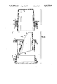
- FIG. 1 is a fragmentary front elevational view in cross-section of the inventive liquid dispenser package
- FIG. 1A is a partial cross-sectional detail view taken along lines 1A--1A in FIG. 1;
- FIG. 2 is a fragmentary front elevational view of the liquid dispenser container with spout fitment thereon;
- FIG. 3 is a fragmentary, exploded front elevational cross-sectional view of the liquid dispenser package of FIG. 1;
- FIG. 4 is a fragmentary cross-sectional view taken along lines 4--4 in FIG. 1 and showing details of interengagement between the container finish and spout fitment;
- FIG. 5A is an enlarged partial cross-sectional detail view taken along lines 5A--5A in FIG. 4;
- FIG. 5B is an enlarged partial cross-sectional detail view taken along lines 5B--5B in FIG. 4;
- FIG. 6A is an enlarged detail view taken along lines 6A--6A in FIG. 5A;
- FIG. 6B is an enlarged detail view taken along lines 6B--6B in FIG. 5B;
- FIG. 7 is a top plan view taken along lines 7--7 in FIG. 3 and showing the spout fitment
- FIG. 8 is a top plan view taken along lines 8--8 in FIG. 3 and showing details of the interlock means on the container finish;
- FIG. 9 is an enlarged partial cross-sectional detail view of a first alternate embodiment of the spout fitment
- FIG. 10 is an enlarged partial cross-sectional detail view of a second alternate embodiment of the spout fitment.
- FIG. 11 is an enlarged partial cross-sectional detail view of a third alternate embodiment of the spout fitment.
- FIG. 1 a preferred embodiment of the inventive package generally at 10.
- Package 10 comprises generally a hollow liquid container shown at 12, a spout fitment generally at 14, and a measuring cup generally at 16 as will be more fully described hereinafter.
- Container 12 may be conveniently made of a polyolefin such as high-density polyethylene plastic material.
- the container has a body portion 18 and an upwardly extending finish 20 having an opening 21 in the upper end thereof An end wall 22 is provided at the upper end for sealing.
- Body portion 18, including that which is not shown, may be of any suitable configuration so as to provide a closed-end chamber 24 for receiving liquids to be dispensed.
- Fitted within the opening 21 is a spout fitment 26 which may be made of an injection-molded polyolefin such as low-density polyethylene plastic material.
- Fitment 26 is comprised of a downwardly directed frustoconical, inwardly sloping side wall 28 and an interiorally spaced frustoconical spout 30 for dispensing liquids.
- Spout 30 has an inlet opening 32 in communication with chamber 24 and an outlet opening 34.
- Connecting spout 30 with side wall 28 is an angled transition wall 36, as best seen in FIG. 7.
- a depending annular skirt 46 Radially outward of side wall 28 is a depending annular skirt 46 having an interior annular bead 48 which mechanically mates with an accommodating groove 50 on the exterior of finish 20.
- Skirt 46 is joined to side wall 28 by means of a radially directed flat annular flange 52 having sealing surfaces 54, 56 on the upper and lower sides thereof. Lower sealing surface 56 sealingly mates with end wall 22 of finish 20.
- measuring cup 16 it may be made of an injection-molded polyolefin such as polypropylene plastic material.
- the cup comprises a generally cylindrical side wall 58 having a generally planar bottom wall 60 closing one end. The other end defines an opening 61.
- the cup 16 functions not only to measure liquid to be dispensed when it is removed and inverted, but also to act as a cap closure for the container 12 when it is fully engaged on the container.
- radially outward of side wall 58 is a depending skirt 62.
- This skirt is integrally connected to side wall 58 by means of a radially directed annular flange 64 having a lower sealing surface 65 located intermediate the closed end 60 and the open end 61 of the cup 16.
- a sealing bead of a convenient shape such as "V"-shaped annular ridge 67 is molded into the lower sealing surface 65 of flange 64.
- This "V" ridge is aligned with flange 52 of fitment 14 and end wall 22 of finish 20 so that a concentrated sealing force is produced as best seen in FIG. 1A.
- Also assisting in concentrating the force is the provision of a pair of bevel angles X, Y on end wall 22 of finish 20.
- the bevel angles X and Y may conveniently be 2° and 8°, respectively.
- Located on the interior wall 66 of skirt 62 are a plurality of threads 68 which produce this force when the cup 16 is rotated onto the container and the threads are interengaged.
- threads 68 interengage with corresponding threads 70 on the outer wall 72 of finish 20. Threads 68 also interengage with thread 74 on bottom periphery of the outer wall 76 of skirt 46.
- threads 70 cooperate with thread 74 to provide a continuous thread to interengage with the cup threads (not shown).
- thread 70 ends with an end surface such as angled end surface 78 which abuts an accommodating end surface such as angled end surface 80 on thread 74.
- Thread 74 makes just a single circumference of fitment 26 and stops adjacent to its starting flat surface 82 although it could make more or fewer turns.
- Threads 70 make slightly more than one circumference of finish 20 as shown although it could be longer or shorter as well.
- This abutment 78 has an additional function of orienting the fitment 26 and spout 30 thereon with respect to the liquid container 10, which may have a handle (not shown). It also functions to prevent rotation of fitment 26 with respect to finish 20 when cup 16 is rotated into its fully engaged position wherein it serves as a cap closure for the container.
- cup 16 is shown in its fully engaged position wherein it serves as a cap closure for container 10.
- outer wall surface 82 of side wall 58 of cup 16 is in contact with inner wall surface 84 of side wall 28 of fitment 14.
- the thus contacting surfaces of cup 16 and fitment 14 are closely fitted so that centering is produced therebetween.
- This centering of the cup with respect to the fitment also centers the threads 68 with respect to threads 70, 74 for equal force distribution around the circumference when the cup 14 is fully rotationally engaged. This produces an even distribution of forces between upper and lower sealing surfaces 54, 56 so that "V" ridge 67 is evenly compressed.
- the remainder of the outer wall surface 86 is tapered and spaced from inner wall surface 82.
- an interlock and centering means 88 comprises a plurality of locking teeth 90 and ramps 92, 94 integrally molded into the finish 20 and fitment 26, respectively.
- the interlock and centering means is provided for a first purpose of preventing rotation of the fitment 26 with respect to said finish 20 when the cap (not shown) is rotated off the container.
- the ramps in opposite quadrants have two shapes.
- the first is a one-sided ramp 92 as perhaps best seen in FIGS. 5A and 6A.
- These one-side ramps have a leading edge wall 96 which are at an obtuse angle B to a tangent to the side wall 98 of finish 20.
- the obtuse angle B may conveniently be 150°.
- the trailing edge wall 100 is radially directed to a tangent to side wall 98 of finish 20. This angle may conveniently be 90°.
- the included angle A between leading edge wall 96 and trailing edge wall 100 may conveniently be 60°.
- Teeth 90 are generally rectangular and projecting from the inner wall surface 102 of fitment 26. These teeth in their normal, undeformed state project at an angle D which may conveniently be 45° to a tangent to inner wall surface 102. Each of the teeth includes a radially directed end wall 104 which is adapted to contact and stop against a trailing edge wall 100. In this manner rotation in one direction is prevented. As may be seen, the teeth and ramps are evenly spaced so that the twice distance d1 between every tooth is substantially equal to one-and-one-half times the distance d2 between each one-sided ramp 92. To put it another way, there are three ramps for every two teeth. Other ratios and spacings are also possible.
- the teeth and ramps are so spaced such that the contact of teeth to ramps produces the interlock and centering function. It does this by having teeth contact the leading edge, trailing edge, or apexes of ramps at sufficient points about the circumference of the fitment and finish.
- the radial height h1 of each tooth is substantially equal to the distance between side wall 98 of finish 20 and wall surface 102 of fitment 26.
- the radial height h2 of one-sided ramps 92 is less so that teeth 90 may flex and deform and pass over ramps 92 as the fitment 26 attempts to be relatively rotated to the left with respect to the finish 20 as viewed in the drawing of FIG. 5A.
- the ratio of height h1 to h2 may conveniently be 4 to 3.
- the teeth 90 remain the same so need no further discussion.
- the ramps 94 are shown to be two-sided. Again, they have a leading edge wall 96'. They also have a trailing edge wall 100' which is also at an angle.
- the two acute angles A' and C' between the radial direction and the respective walls 96' and 100' may be equal and may conveniently be 70°.
- the obtuse angle B' may conveniently be 160°.
- the radial height h1' equals radial height h1.
- the radial height of each tooth h1' bears a ratio of 2 to 1 with respect to the height of each two-sided ramp 94.
- the one- and two-side ramps 92, 94, respectively may be of equal width w2, w2'. Teeth 90 can have a shorter width w1, w1' which may both be equal.
- the one- and two-sided ramps 92, 94 may also be seen in FIG. 8. As shown therein, one-sided ramps 92 are located on opposite quadrants from each other and on intermediate quadrants from the two-sided ramps 94. At least two purposes are served by having the two-sided ramp on opposite quadrants and one-sided ramps on the remaining quadrants. First of all, the two-sided ramps permit the container to be removed from the mold after blow-molding with conventional extrusion blow-molding equipment. If the ramps were all one-sided around the finish of the container, the container could not be removed from the mold halves (not shown).
- a second fundamental purpose for having two-sided ramps or any kind of ramp is that of centering of the fitment 26 with respect to the finish 20. This centering is accomplished as seen in FIG. 5B by the teeth 90 contacting some portion of the leading or trailing edge walls 96' or 100', respectively.
- This centering of the fitment with respect to the finish helps to prevent misalignment of the subject parts and thereby assist the sealing system in preventing unwanted leakage of liquid from the container around the parts. It accomplishes this by positioning fitment 14 with respect to finish 20 so that sealing forces are concentrated on the apex of the finish. As best seen in FIG.
- finish 20 is centered with respect to fitment 14 to be on a common axis so that annular apex 106 formed by the intersection of beveled surfaces 108, 110 on end wall 22 is on a line of contact.
- "V" ridge 67 on cup 16 is on the same line of contact due to the dimensional control between outer and inner wall surfaces 82, 84 which results in the cup being on the same common axis with the finish and fitment. In this manner, "V" ridge 67 will be on a direct line of contact with apex 106 with flange 52 sandwiched therebetween.
- FIGS. 9-11 several alternate embodiments are shown wherein a seal bead is added to enhance the sealing effect.
- FIGS. 9-11 show exemplary bead structures and other structures are also contemplated which provide the necessary sealing function.
- a bead 112 of generally rectangular cross-section but having a "V" groove 114 in the lowermost portion thereof so as to form a pair of spaced, concentric downwardly directed annular ridges 116, 118. These ridges seal with end wall 22.
- a "V"-shaped annular bead 112 is shown on lower sealing surface 56 of flange 52. This bead 112' sealingly mates with end wall 22 of the finish.
- FIG. 11 shows a bead 112'' having a generally rectangular cross-section. This bead sealingly contacts apex 106 formed on end wall 22.
Abstract
Description
Claims (19)
Priority Applications (2)
| Application Number | Priority Date | Filing Date | Title |
|---|---|---|---|
| US07/209,221 US4917268A (en) | 1988-06-20 | 1988-06-20 | Liquid dispensing package with drainback spout |
| EP89306065A EP0348102A1 (en) | 1988-06-20 | 1989-06-15 | Liquid dispensing package with drainback spout |
Applications Claiming Priority (1)
| Application Number | Priority Date | Filing Date | Title |
|---|---|---|---|
| US07/209,221 US4917268A (en) | 1988-06-20 | 1988-06-20 | Liquid dispensing package with drainback spout |
Publications (1)
| Publication Number | Publication Date |
|---|---|
| US4917268A true US4917268A (en) | 1990-04-17 |
Family
ID=22777859
Family Applications (1)
| Application Number | Title | Priority Date | Filing Date |
|---|---|---|---|
| US07/209,221 Expired - Lifetime US4917268A (en) | 1988-06-20 | 1988-06-20 | Liquid dispensing package with drainback spout |
Country Status (2)
| Country | Link |
|---|---|
| US (1) | US4917268A (en) |
| EP (1) | EP0348102A1 (en) |
Cited By (62)
| Publication number | Priority date | Publication date | Assignee | Title |
|---|---|---|---|---|
| US5181630A (en) * | 1991-06-19 | 1993-01-26 | The Procter & Gamble Company | Vessel having dual function pouring spout for spot treating or rapid transfer of viscous liquids |
| US5228596A (en) * | 1991-06-19 | 1993-07-20 | The Procter & Gamble Company | Outwardly projecting directed pour spout exhibiting thread compatible cross-sectional profile |
| US5251788A (en) * | 1992-04-23 | 1993-10-12 | Phoenix Closures, Inc. | Pour spout and dispenser closure with drainage feature |
| US5431306A (en) * | 1993-12-31 | 1995-07-11 | Innovative Molding, Inc. | Drain back container with internal thread |
| US5435467A (en) * | 1994-04-20 | 1995-07-25 | Phoenix Closures, Inc. | Stackable dispenser closure |
| US5462202A (en) * | 1994-08-25 | 1995-10-31 | Owens-Illinois Closure Inc. | Liquid containing and dispensing package |
| US5533553A (en) * | 1994-01-26 | 1996-07-09 | Colgate-Palmolive Co. | Container set comprising at least two containers |
| US5549209A (en) * | 1995-03-03 | 1996-08-27 | Colgate-Palmolive Company | Closure brush |
| US5566862A (en) * | 1994-10-24 | 1996-10-22 | Owens-Illinois Closure Inc. | Liquid containing and dispensing package |
| US5641099A (en) * | 1995-12-08 | 1997-06-24 | Rieke Corporation | Nestable pouring spout assembly |
| US5746260A (en) * | 1994-01-26 | 1998-05-05 | Colgate-Palmolive Company | Container set comprising at least two containers |
| WO1998045207A1 (en) | 1997-04-04 | 1998-10-15 | Graham Packaging Corporation | Plastic container dispensing fitment |
| US5868283A (en) * | 1996-07-02 | 1999-02-09 | Lever Brothers Company, Division Of Conopco, Inc. | Reclosable closure and bottle |
| US5941422A (en) * | 1998-04-06 | 1999-08-24 | Owens-Brockway Plastic Products Inc. | Liquid containing and dispensing package |
| US6500380B1 (en) * | 1998-07-13 | 2002-12-31 | Owens Brockway Plastic Products Inc. | Method and apparatus for making a plastic container with drain back spout |
| US6530500B2 (en) * | 1999-07-08 | 2003-03-11 | The Sherwin-Williams Company | Storage and dispensing container for viscous fluids, paints and the like, and method of minimizing dripping |
| USD472145S1 (en) | 2001-08-14 | 2003-03-25 | Nottingham-Spirk Partners, Llc | Paint container lid |
| USD473790S1 (en) | 2001-08-14 | 2003-04-29 | Nottingham-Spirk Partners, Llc | Paint container insert |
| US20030188986A1 (en) * | 2000-04-11 | 2003-10-09 | Wylie Arun M. | Container |
| USD480973S1 (en) | 2001-08-14 | 2003-10-21 | Nsi Innovation Llp | Design for a round paint container |
| WO2003088791A1 (en) * | 2002-04-19 | 2003-10-30 | Rieke Corporation | Improved container for holding a product |
| USD482973S1 (en) | 2001-08-14 | 2003-12-02 | Nsi Innovation Llc | Square paint container |
| US20040011831A1 (en) * | 2002-07-03 | 2004-01-22 | Mcdonald Robert E. | Plastic paint container having a cube-shaped body |
| US20040011825A1 (en) * | 2002-07-19 | 2004-01-22 | Mclelland Douglas M. | Container for liquids, including sealing mechanisms |
| US20050006418A1 (en) * | 2003-06-25 | 2005-01-13 | Doron Rigel | Retractable spout assembly for bottles |
| US20050023293A1 (en) * | 2002-07-19 | 2005-02-03 | Kasting Thomas P. | Sealing mechanisms for use in liquid-storage containers |
| US20050087548A1 (en) * | 2003-10-24 | 2005-04-28 | Erie County Plastics Corporation | Drain-back snap-on pour spout fitment closure |
| US20050092784A1 (en) * | 2003-10-28 | 2005-05-05 | Masterchem Industries, Inc. | Container spout |
| US20050139609A1 (en) * | 2003-12-30 | 2005-06-30 | Unilever Home & Personal Care Usa | Pour spout fitment and container |
| US20050188911A1 (en) * | 2004-03-01 | 2005-09-01 | Masterchem Industries, Inc. | Torque indicator |
| US7036693B2 (en) | 2001-12-05 | 2006-05-02 | Masterchem Industries Llc | Paint container |
| US20060097006A1 (en) * | 2005-10-11 | 2006-05-11 | Erie County Plastics Corporation | Pour spout fitment with internal cut off |
| US20060131330A1 (en) * | 2004-12-21 | 2006-06-22 | Erie County Plastics Corporation | Drain-back spout fitment closure with drip-less pour tip |
| US20060163252A1 (en) * | 2005-01-24 | 2006-07-27 | Letica Corporation | Container |
| US20060201977A1 (en) * | 2002-07-19 | 2006-09-14 | Rieke Corporation | Sealing mechanisms for use in liquid-storage containers |
| US20070257057A1 (en) * | 2004-11-15 | 2007-11-08 | The Procter & Gamble Company | Transitions for containers |
| US20080142547A1 (en) * | 2006-12-13 | 2008-06-19 | Conopco, Inc., D/B/A Unilever | Liquids dispensing container with spouted fitment and anti-backoff and anti-rotation features |
| US20080164282A1 (en) * | 2006-06-15 | 2008-07-10 | Plastek Industries, Inc. | Pour Spout |
| US20080283552A1 (en) * | 2007-05-17 | 2008-11-20 | Penny Michael E | Molded preform and container having integrated pour spout |
| US20090045224A1 (en) * | 2007-08-17 | 2009-02-19 | Joel Faaborg | Liquid product pouring and measuring package with drain-back spout fitment and tight-sealing measuring cup assembly |
| US20090101682A1 (en) * | 2005-06-15 | 2009-04-23 | Plastek Industries, Inc. | Pour Spout |
| US20090314738A1 (en) * | 2008-06-23 | 2009-12-24 | Siacunco James P | Bottle cap with internal brush |
| US20100043910A1 (en) * | 2006-02-06 | 2010-02-25 | Plastek Industries, Inc. | Pour Spout |
| US20100116776A1 (en) * | 2007-05-31 | 2010-05-13 | Plastek Industries, Inc. | Pour Spout |
| US20100213211A1 (en) * | 2009-02-26 | 2010-08-26 | Whaling Audrey M | Bottle Cap With Dosing and Pretreatment |
| US20110089195A1 (en) * | 2007-05-17 | 2011-04-21 | Amcor Limited | Molded preform and container having integrated pour spout |
| US20110163108A1 (en) * | 2010-01-07 | 2011-07-07 | Stiefel Laboratories, Inc. | Container venting disc |
| US20120012552A1 (en) * | 2010-07-16 | 2012-01-19 | Kubicek Chris A | Refill For And A Method Of Inserting A Refill Into A Volatile Material Dispenser |
| US20120043295A1 (en) * | 2010-08-20 | 2012-02-23 | Judith Webster | Child resistant flip-top closure with pouring spout |
| CN102530372A (en) * | 2012-02-20 | 2012-07-04 | 力帆实业(集团)股份有限公司 | Flow guiding inner cover for engine oil bottle |
| CN102530371A (en) * | 2012-02-20 | 2012-07-04 | 力帆实业(集团)股份有限公司 | Engine oil bottle |
| US20130161281A1 (en) * | 2011-06-08 | 2013-06-27 | Mwv Slatersville, Llc | Dispensing closure |
| US8663419B2 (en) | 2010-11-30 | 2014-03-04 | Ecologic | Manual container assembly and liner integration fixture for pulp-molded shell with polymer liner container systems |
| US20140144948A1 (en) * | 2012-11-26 | 2014-05-29 | Daniel John Brausen | Self-Ventilating Container |
| US8757453B1 (en) * | 2007-01-10 | 2014-06-24 | Sven O. Olsson | Pouring spout |
| RU2568101C2 (en) * | 2010-04-29 | 2015-11-10 | Дорон РИГЕЛЬ | Auxiliary device for installation together with cap on bottle for riveting of sliding nose to bottle |
| US9187219B2 (en) | 2013-03-06 | 2015-11-17 | Westrock Slatersville, Llc | Pour lip closure with drain back |
| US9365808B2 (en) | 2011-09-28 | 2016-06-14 | Eric Sternberg | Composition and system for treating a drain and methods thereof |
| US9371165B2 (en) | 2013-08-16 | 2016-06-21 | Westrock Slatersville, Llc | Two-piece child-resistant dispensing closure |
| US9446885B2 (en) | 2012-11-10 | 2016-09-20 | Kraft Foods Group Brands Llc | Container with a removable measuring cap |
| US10167118B1 (en) * | 2016-04-28 | 2019-01-01 | Plastek Industries, Inc. | Closure cap with a flange upper surface having an interrupted annular recess |
| US20220041346A1 (en) * | 2018-09-14 | 2022-02-10 | Alpla Werke Alwin Lehner Gmbh & Co. Kg | Plastic container comprising a pouring element |
Families Citing this family (3)
| Publication number | Priority date | Publication date | Assignee | Title |
|---|---|---|---|---|
| US5058772A (en) * | 1989-11-13 | 1991-10-22 | Phoenix Closures, Inc. | Dispenser closure with drain back feature |
| FR2703978B1 (en) * | 1993-04-16 | 1998-01-09 | Roger Pellegrino | Pouring device with drop sensor. |
| CN106458395A (en) * | 2014-05-29 | 2017-02-22 | 卢姆森股份公司 | A safety closure for containers |
Citations (29)
| Publication number | Priority date | Publication date | Assignee | Title |
|---|---|---|---|---|
| US2061685A (en) * | 1935-03-15 | 1936-11-24 | Owens Illinois Glass Co | Closure |
| US2601040A (en) * | 1950-07-05 | 1952-06-17 | Livingstone Jay Gould | Fitting and sealing means therefor |
| US2601039A (en) * | 1949-12-01 | 1952-06-17 | Livingstone Jay Gould | Pouring spout |
| US2715480A (en) * | 1953-03-09 | 1955-08-16 | Jay G Livingstone | Container adapter provided with pouring spout, drip return, and cap |
| US2743844A (en) * | 1956-05-01 | livingstone | ||
| US2763403A (en) * | 1953-06-16 | 1956-09-18 | Jay G Livingstone | Fittings |
| US3201014A (en) * | 1957-11-25 | 1965-08-17 | Jay G Livingstone | Perforate plastic fitment with bottom which is at least partly flat in pressure contact with flat portion of top of container |
| US3300104A (en) * | 1965-07-09 | 1967-01-24 | Procter & Gamble | Pouring adapter for liquid containers |
| US3369710A (en) * | 1966-11-01 | 1968-02-20 | Procter & Gamble | Pouring fitment |
| US3628697A (en) * | 1969-02-08 | 1971-12-21 | D P Inserts Ltd | Drip-preventing device for bottle |
| US3833150A (en) * | 1971-06-16 | 1974-09-03 | Patings W Visser | Pouring stop |
| JPS51129658A (en) * | 1975-04-30 | 1976-11-11 | Matsushita Electric Works Ltd | Reed relay |
| US4078700A (en) * | 1974-08-05 | 1978-03-14 | Hidding Walter E | Dripless pouring spout and closure cap therefor |
| US4218189A (en) * | 1977-08-09 | 1980-08-19 | Rolls-Royce Limited | Sealing means for bladed rotor for a gas turbine engine |
| US4273247A (en) * | 1980-01-28 | 1981-06-16 | Schenley Industries, Inc. | Bottle closure-cup assembly |
| US4298129A (en) * | 1980-05-02 | 1981-11-03 | Morton Stull | Childproof, snap-on, twist-off safety cap and container |
| US4298145A (en) * | 1979-03-09 | 1981-11-03 | Motoyori Iida | Adapter for a container |
| US4349056A (en) * | 1979-12-29 | 1982-09-14 | The Procter & Gamble Company | Container for liquid with non-drip measuring cap closure |
| DE3207223A1 (en) * | 1982-03-01 | 1983-09-08 | Henkel KGaA, 4000 Düsseldorf | DOSING SCREW CAP |
| US4494682A (en) * | 1982-07-07 | 1985-01-22 | Hunt-Wesson Foods, Inc. | Pouring fitment with container and closure therefor |
| US4533058A (en) * | 1984-11-28 | 1985-08-06 | Owens-Illinois, Inc. | One-piece thermoplastic child-resistent dispensing closure |
| US4550862A (en) * | 1982-11-17 | 1985-11-05 | The Procter & Gamble Company | Liquid product pouring and measuring package with self draining feature |
| US4600131A (en) * | 1983-11-30 | 1986-07-15 | Thoroughbred Plastics Corp. | Pourout fitment/closure |
| EP0214675A2 (en) * | 1985-08-01 | 1987-03-18 | Procter & Gamble European Technical Center | Blow molded container having a first and a second internal attachment means |
| US4671421A (en) * | 1986-03-06 | 1987-06-09 | Owens-Illinois, Inc. | Plastic container |
| US4696416A (en) * | 1984-09-28 | 1987-09-29 | The Procter & Gamble Company | Liquid product dispensing package with self draining feature employing drip concentrator |
| US4706829A (en) * | 1986-02-07 | 1987-11-17 | Owens-Illinois Closure Inc. | Liquid containing and dispensing package |
| EP0255062A2 (en) * | 1986-08-01 | 1988-02-03 | Henkel Kommanditgesellschaft auf Aktien | Measuring cup closure and method of fitting of the closure |
| JPH0551342A (en) * | 1991-08-22 | 1993-03-02 | Mitsubishi Kasei Corp | Chain terpene |
Family Cites Families (1)
| Publication number | Priority date | Publication date | Assignee | Title |
|---|---|---|---|---|
| ATE30136T1 (en) * | 1982-11-17 | 1987-10-15 | Procter & Gamble | PACKAGING CONTAINER FOR LIQUIDS WITH SPOUTING DEVICE AND MEASURING CUP AND DRIPPING DEVICE. |
-
1988
- 1988-06-20 US US07/209,221 patent/US4917268A/en not_active Expired - Lifetime
-
1989
- 1989-06-15 EP EP89306065A patent/EP0348102A1/en not_active Ceased
Patent Citations (30)
| Publication number | Priority date | Publication date | Assignee | Title |
|---|---|---|---|---|
| US2743844A (en) * | 1956-05-01 | livingstone | ||
| US2061685A (en) * | 1935-03-15 | 1936-11-24 | Owens Illinois Glass Co | Closure |
| US2601039A (en) * | 1949-12-01 | 1952-06-17 | Livingstone Jay Gould | Pouring spout |
| US2601040A (en) * | 1950-07-05 | 1952-06-17 | Livingstone Jay Gould | Fitting and sealing means therefor |
| US2715480A (en) * | 1953-03-09 | 1955-08-16 | Jay G Livingstone | Container adapter provided with pouring spout, drip return, and cap |
| US2763403A (en) * | 1953-06-16 | 1956-09-18 | Jay G Livingstone | Fittings |
| US3201014A (en) * | 1957-11-25 | 1965-08-17 | Jay G Livingstone | Perforate plastic fitment with bottom which is at least partly flat in pressure contact with flat portion of top of container |
| US3300104A (en) * | 1965-07-09 | 1967-01-24 | Procter & Gamble | Pouring adapter for liquid containers |
| US3369710A (en) * | 1966-11-01 | 1968-02-20 | Procter & Gamble | Pouring fitment |
| US3628697A (en) * | 1969-02-08 | 1971-12-21 | D P Inserts Ltd | Drip-preventing device for bottle |
| US3833150A (en) * | 1971-06-16 | 1974-09-03 | Patings W Visser | Pouring stop |
| US4078700A (en) * | 1974-08-05 | 1978-03-14 | Hidding Walter E | Dripless pouring spout and closure cap therefor |
| JPS51129658A (en) * | 1975-04-30 | 1976-11-11 | Matsushita Electric Works Ltd | Reed relay |
| US4218189A (en) * | 1977-08-09 | 1980-08-19 | Rolls-Royce Limited | Sealing means for bladed rotor for a gas turbine engine |
| US4298145A (en) * | 1979-03-09 | 1981-11-03 | Motoyori Iida | Adapter for a container |
| US4349056A (en) * | 1979-12-29 | 1982-09-14 | The Procter & Gamble Company | Container for liquid with non-drip measuring cap closure |
| US4273247A (en) * | 1980-01-28 | 1981-06-16 | Schenley Industries, Inc. | Bottle closure-cup assembly |
| US4298129A (en) * | 1980-05-02 | 1981-11-03 | Morton Stull | Childproof, snap-on, twist-off safety cap and container |
| DE3207223A1 (en) * | 1982-03-01 | 1983-09-08 | Henkel KGaA, 4000 Düsseldorf | DOSING SCREW CAP |
| US4494682A (en) * | 1982-07-07 | 1985-01-22 | Hunt-Wesson Foods, Inc. | Pouring fitment with container and closure therefor |
| US4550862A (en) * | 1982-11-17 | 1985-11-05 | The Procter & Gamble Company | Liquid product pouring and measuring package with self draining feature |
| US4600131A (en) * | 1983-11-30 | 1986-07-15 | Thoroughbred Plastics Corp. | Pourout fitment/closure |
| US4696416A (en) * | 1984-09-28 | 1987-09-29 | The Procter & Gamble Company | Liquid product dispensing package with self draining feature employing drip concentrator |
| US4533058A (en) * | 1984-11-28 | 1985-08-06 | Owens-Illinois, Inc. | One-piece thermoplastic child-resistent dispensing closure |
| EP0214675A2 (en) * | 1985-08-01 | 1987-03-18 | Procter & Gamble European Technical Center | Blow molded container having a first and a second internal attachment means |
| US4706829A (en) * | 1986-02-07 | 1987-11-17 | Owens-Illinois Closure Inc. | Liquid containing and dispensing package |
| US4671421A (en) * | 1986-03-06 | 1987-06-09 | Owens-Illinois, Inc. | Plastic container |
| EP0255062A2 (en) * | 1986-08-01 | 1988-02-03 | Henkel Kommanditgesellschaft auf Aktien | Measuring cup closure and method of fitting of the closure |
| US4773560A (en) * | 1986-08-01 | 1988-09-27 | Henkel Kommanditgesellschaft Auf Aktien | Measuring cup closure and method for fitting the closure |
| JPH0551342A (en) * | 1991-08-22 | 1993-03-02 | Mitsubishi Kasei Corp | Chain terpene |
Cited By (106)
| Publication number | Priority date | Publication date | Assignee | Title |
|---|---|---|---|---|
| US5228596A (en) * | 1991-06-19 | 1993-07-20 | The Procter & Gamble Company | Outwardly projecting directed pour spout exhibiting thread compatible cross-sectional profile |
| US5181630A (en) * | 1991-06-19 | 1993-01-26 | The Procter & Gamble Company | Vessel having dual function pouring spout for spot treating or rapid transfer of viscous liquids |
| US5251788A (en) * | 1992-04-23 | 1993-10-12 | Phoenix Closures, Inc. | Pour spout and dispenser closure with drainage feature |
| US5603787A (en) * | 1993-12-31 | 1997-02-18 | Innovative Molding, Inc. | Drain back container assembly |
| US5431306A (en) * | 1993-12-31 | 1995-07-11 | Innovative Molding, Inc. | Drain back container with internal thread |
| US5533553A (en) * | 1994-01-26 | 1996-07-09 | Colgate-Palmolive Co. | Container set comprising at least two containers |
| US5746260A (en) * | 1994-01-26 | 1998-05-05 | Colgate-Palmolive Company | Container set comprising at least two containers |
| US5435467A (en) * | 1994-04-20 | 1995-07-25 | Phoenix Closures, Inc. | Stackable dispenser closure |
| US5462202A (en) * | 1994-08-25 | 1995-10-31 | Owens-Illinois Closure Inc. | Liquid containing and dispensing package |
| US5566862A (en) * | 1994-10-24 | 1996-10-22 | Owens-Illinois Closure Inc. | Liquid containing and dispensing package |
| US5549209A (en) * | 1995-03-03 | 1996-08-27 | Colgate-Palmolive Company | Closure brush |
| US5641099A (en) * | 1995-12-08 | 1997-06-24 | Rieke Corporation | Nestable pouring spout assembly |
| US5797525A (en) * | 1995-12-08 | 1998-08-25 | Rieke Corporation | Nestable pouring spout assembly |
| US5868283A (en) * | 1996-07-02 | 1999-02-09 | Lever Brothers Company, Division Of Conopco, Inc. | Reclosable closure and bottle |
| WO1998045207A1 (en) | 1997-04-04 | 1998-10-15 | Graham Packaging Corporation | Plastic container dispensing fitment |
| US5855299A (en) * | 1997-04-04 | 1999-01-05 | Graham Packaging Corporation | Plastic container dispensing fitment |
| US5941422A (en) * | 1998-04-06 | 1999-08-24 | Owens-Brockway Plastic Products Inc. | Liquid containing and dispensing package |
| US6500380B1 (en) * | 1998-07-13 | 2002-12-31 | Owens Brockway Plastic Products Inc. | Method and apparatus for making a plastic container with drain back spout |
| US6634525B2 (en) * | 1999-07-08 | 2003-10-21 | The Sherwin-Williams Company | Storage and dispensing container for paint |
| US6530500B2 (en) * | 1999-07-08 | 2003-03-11 | The Sherwin-Williams Company | Storage and dispensing container for viscous fluids, paints and the like, and method of minimizing dripping |
| US20050028884A1 (en) * | 1999-07-08 | 2005-02-10 | The Sherwin Williams Company | Storage and dispensing container for paint |
| US7325687B2 (en) | 1999-07-08 | 2008-02-05 | The Sherwin-Williams Company | Storage and dispensing container for paint |
| US7703641B2 (en) * | 1999-07-08 | 2010-04-27 | The Sherwin-Williams Company | Storage and dispensing container for paint |
| US20060288660A1 (en) * | 2000-04-11 | 2006-12-28 | Wylie Arun M | Container |
| US20060163106A1 (en) * | 2000-04-11 | 2006-07-27 | Wylie Arun M | Container |
| US20060163107A1 (en) * | 2000-04-11 | 2006-07-27 | Wylie Arun M | Container |
| US7032756B2 (en) | 2000-04-11 | 2006-04-25 | Wylie Arun M | Container |
| US20060163105A1 (en) * | 2000-04-11 | 2006-07-27 | Wylie Arun M | Container |
| US20060016713A1 (en) * | 2000-04-11 | 2006-01-26 | Wylie Arun M | Container |
| US20060163108A1 (en) * | 2000-04-11 | 2006-07-27 | Wylie Arun M | Container |
| US20030188986A1 (en) * | 2000-04-11 | 2003-10-09 | Wylie Arun M. | Container |
| US20060283756A1 (en) * | 2000-04-11 | 2006-12-21 | Wylie Arun M | Container |
| US20070074487A1 (en) * | 2000-04-11 | 2007-04-05 | Wylie Arun M | Container |
| US20070000804A1 (en) * | 2000-04-11 | 2007-01-04 | Wylie Arun M | Container |
| US20060289326A1 (en) * | 2000-04-11 | 2006-12-28 | Wylie Arun M | Container |
| US20060289543A1 (en) * | 2000-04-11 | 2006-12-28 | Wylie Arun M | Container |
| USD472145S1 (en) | 2001-08-14 | 2003-03-25 | Nottingham-Spirk Partners, Llc | Paint container lid |
| USD473790S1 (en) | 2001-08-14 | 2003-04-29 | Nottingham-Spirk Partners, Llc | Paint container insert |
| USD480973S1 (en) | 2001-08-14 | 2003-10-21 | Nsi Innovation Llp | Design for a round paint container |
| USD482973S1 (en) | 2001-08-14 | 2003-12-02 | Nsi Innovation Llc | Square paint container |
| US7036693B2 (en) | 2001-12-05 | 2006-05-02 | Masterchem Industries Llc | Paint container |
| US20060289570A1 (en) * | 2002-04-19 | 2006-12-28 | Rohr Robert D | Container for holding a product |
| WO2003088791A1 (en) * | 2002-04-19 | 2003-10-30 | Rieke Corporation | Improved container for holding a product |
| AU2003228605B2 (en) * | 2002-04-19 | 2008-07-17 | Rieke Corporation | Improved container for holding a product |
| US20040026450A1 (en) * | 2002-04-19 | 2004-02-12 | Rohr Robert D. | Container for holding a product |
| US20040011831A1 (en) * | 2002-07-03 | 2004-01-22 | Mcdonald Robert E. | Plastic paint container having a cube-shaped body |
| US6896156B2 (en) | 2002-07-03 | 2005-05-24 | The Sherwin-Williams Company | Plastic paint container having a cube-shaped body |
| US20040011825A1 (en) * | 2002-07-19 | 2004-01-22 | Mclelland Douglas M. | Container for liquids, including sealing mechanisms |
| US7347343B2 (en) * | 2002-07-19 | 2008-03-25 | Rieke Corporation | Container for liquids, including sealing mechanisms |
| US20050023293A1 (en) * | 2002-07-19 | 2005-02-03 | Kasting Thomas P. | Sealing mechanisms for use in liquid-storage containers |
| US7677423B2 (en) | 2002-07-19 | 2010-03-16 | Rieke Corporation | Sealing mechanisms for use in liquid-storage containers |
| US20060201977A1 (en) * | 2002-07-19 | 2006-09-14 | Rieke Corporation | Sealing mechanisms for use in liquid-storage containers |
| US7216779B2 (en) * | 2002-07-19 | 2007-05-15 | Rieke Corporation | Sealing mechanisms for use in liquid-storage containers |
| US6976610B2 (en) * | 2003-06-25 | 2005-12-20 | Doron Rigel | Retractable spout assembly for bottles |
| WO2004113176A3 (en) * | 2003-06-25 | 2005-04-21 | Doron Rigel | Retractable spout assembly for bottles |
| US20050006418A1 (en) * | 2003-06-25 | 2005-01-13 | Doron Rigel | Retractable spout assembly for bottles |
| US6923341B2 (en) | 2003-10-24 | 2005-08-02 | Erie County Plastics Corporation | Drain-back snap-on pour spout fitment closure |
| US20050087548A1 (en) * | 2003-10-24 | 2005-04-28 | Erie County Plastics Corporation | Drain-back snap-on pour spout fitment closure |
| US7841489B2 (en) | 2003-10-28 | 2010-11-30 | Masterchem Industries, Llc | Container sealing system |
| US20050092784A1 (en) * | 2003-10-28 | 2005-05-05 | Masterchem Industries, Inc. | Container spout |
| US20070272706A1 (en) * | 2003-10-28 | 2007-11-29 | Gilbertson Mark A | Container Sealing System |
| US20050139609A1 (en) * | 2003-12-30 | 2005-06-30 | Unilever Home & Personal Care Usa | Pour spout fitment and container |
| US6968980B2 (en) * | 2003-12-30 | 2005-11-29 | Unilever Home & Personal Care Usa, A Division Of Conopco, Inc. | Pour spout fitment and container |
| US20050188911A1 (en) * | 2004-03-01 | 2005-09-01 | Masterchem Industries, Inc. | Torque indicator |
| US20070257057A1 (en) * | 2004-11-15 | 2007-11-08 | The Procter & Gamble Company | Transitions for containers |
| US7673774B2 (en) * | 2004-11-15 | 2010-03-09 | The Procter & Gamble Company | Transitions for containers |
| US7686188B2 (en) | 2004-12-21 | 2010-03-30 | Berry Plastics Corporation | Drain-back spout fitment closure with drip-less pour tip |
| US20060131330A1 (en) * | 2004-12-21 | 2006-06-22 | Erie County Plastics Corporation | Drain-back spout fitment closure with drip-less pour tip |
| US20060163252A1 (en) * | 2005-01-24 | 2006-07-27 | Letica Corporation | Container |
| US20090101682A1 (en) * | 2005-06-15 | 2009-04-23 | Plastek Industries, Inc. | Pour Spout |
| US20060097006A1 (en) * | 2005-10-11 | 2006-05-11 | Erie County Plastics Corporation | Pour spout fitment with internal cut off |
| US20100043910A1 (en) * | 2006-02-06 | 2010-02-25 | Plastek Industries, Inc. | Pour Spout |
| US8025183B2 (en) | 2006-06-15 | 2011-09-27 | Plastek Industries, Inc. | Pour spout |
| US20080164282A1 (en) * | 2006-06-15 | 2008-07-10 | Plastek Industries, Inc. | Pour Spout |
| US20080142547A1 (en) * | 2006-12-13 | 2008-06-19 | Conopco, Inc., D/B/A Unilever | Liquids dispensing container with spouted fitment and anti-backoff and anti-rotation features |
| US8757453B1 (en) * | 2007-01-10 | 2014-06-24 | Sven O. Olsson | Pouring spout |
| US20080283552A1 (en) * | 2007-05-17 | 2008-11-20 | Penny Michael E | Molded preform and container having integrated pour spout |
| US8177098B2 (en) * | 2007-05-17 | 2012-05-15 | Amcor Limited | Molded preform and container having integrated pour spout |
| US8955716B2 (en) | 2007-05-17 | 2015-02-17 | Amcor Limited | Molded preform and container having integrated pour spout |
| US20110089195A1 (en) * | 2007-05-17 | 2011-04-21 | Amcor Limited | Molded preform and container having integrated pour spout |
| US20100116776A1 (en) * | 2007-05-31 | 2010-05-13 | Plastek Industries, Inc. | Pour Spout |
| US8474657B2 (en) * | 2007-05-31 | 2013-07-02 | Plastek Industries, Inc. | Pour spout |
| US7959034B2 (en) | 2007-08-17 | 2011-06-14 | The Dial Corporation | Liquid product pouring and measuring package with drain-back spout fitment and tight-sealing measuring cup assembly |
| US20090045224A1 (en) * | 2007-08-17 | 2009-02-19 | Joel Faaborg | Liquid product pouring and measuring package with drain-back spout fitment and tight-sealing measuring cup assembly |
| US20090314738A1 (en) * | 2008-06-23 | 2009-12-24 | Siacunco James P | Bottle cap with internal brush |
| US20100213211A1 (en) * | 2009-02-26 | 2010-08-26 | Whaling Audrey M | Bottle Cap With Dosing and Pretreatment |
| US20110163108A1 (en) * | 2010-01-07 | 2011-07-07 | Stiefel Laboratories, Inc. | Container venting disc |
| RU2568101C2 (en) * | 2010-04-29 | 2015-11-10 | Дорон РИГЕЛЬ | Auxiliary device for installation together with cap on bottle for riveting of sliding nose to bottle |
| US20120012552A1 (en) * | 2010-07-16 | 2012-01-19 | Kubicek Chris A | Refill For And A Method Of Inserting A Refill Into A Volatile Material Dispenser |
| US20120043295A1 (en) * | 2010-08-20 | 2012-02-23 | Judith Webster | Child resistant flip-top closure with pouring spout |
| US8511492B2 (en) * | 2010-08-20 | 2013-08-20 | The Clorox Company | Bottle with handle venting inlet and child resistant flip-top closure with pouring spout and drainback hole |
| US8663419B2 (en) | 2010-11-30 | 2014-03-04 | Ecologic | Manual container assembly and liner integration fixture for pulp-molded shell with polymer liner container systems |
| US9126719B2 (en) | 2010-11-30 | 2015-09-08 | Ecologic | Manual container assembly and liner integration fixture for pulp-molded shell with polymer liner container systems |
| US8651304B2 (en) * | 2011-06-08 | 2014-02-18 | Mwv Slatersville, Llc | Dispensing closure |
| US20130161281A1 (en) * | 2011-06-08 | 2013-06-27 | Mwv Slatersville, Llc | Dispensing closure |
| US9365808B2 (en) | 2011-09-28 | 2016-06-14 | Eric Sternberg | Composition and system for treating a drain and methods thereof |
| CN102530372A (en) * | 2012-02-20 | 2012-07-04 | 力帆实业(集团)股份有限公司 | Flow guiding inner cover for engine oil bottle |
| CN102530371A (en) * | 2012-02-20 | 2012-07-04 | 力帆实业(集团)股份有限公司 | Engine oil bottle |
| US9446885B2 (en) | 2012-11-10 | 2016-09-20 | Kraft Foods Group Brands Llc | Container with a removable measuring cap |
| US20140144948A1 (en) * | 2012-11-26 | 2014-05-29 | Daniel John Brausen | Self-Ventilating Container |
| US9096357B2 (en) * | 2012-11-26 | 2015-08-04 | Daniel John Brausen | Self-ventilating container |
| US9187219B2 (en) | 2013-03-06 | 2015-11-17 | Westrock Slatersville, Llc | Pour lip closure with drain back |
| US10106300B2 (en) | 2013-03-06 | 2018-10-23 | Silgan Dispensing Systems Slatersville Llc | Pour lip closure with drain back |
| US9371165B2 (en) | 2013-08-16 | 2016-06-21 | Westrock Slatersville, Llc | Two-piece child-resistant dispensing closure |
| US10167118B1 (en) * | 2016-04-28 | 2019-01-01 | Plastek Industries, Inc. | Closure cap with a flange upper surface having an interrupted annular recess |
| US20220041346A1 (en) * | 2018-09-14 | 2022-02-10 | Alpla Werke Alwin Lehner Gmbh & Co. Kg | Plastic container comprising a pouring element |
Also Published As
| Publication number | Publication date |
|---|---|
| EP0348102A1 (en) | 1989-12-27 |
Similar Documents
| Publication | Publication Date | Title |
|---|---|---|
| US4917268A (en) | Liquid dispensing package with drainback spout | |
| US5547091A (en) | Dispensing container snap hinge closure | |
| CA2003875C (en) | Dispensing cap with means for controlled flow rate and multiple seals | |
| US5303850A (en) | Dispensing cap | |
| US3298415A (en) | Closures for large mouth containers | |
| EP0109704B1 (en) | Liquid product pouring and measuring package with self draining feature | |
| CA2012310C (en) | Multiple chamber dispensing container and closure system | |
| US3439841A (en) | Multiple container package | |
| US3209963A (en) | Captive dispensing closure arrangement | |
| CA1122164A (en) | Pour through stopper | |
| CA1319908C (en) | Plastic container with self-draining feature | |
| EP0544381B1 (en) | Dispensing container snap hinge closure | |
| CA2042128A1 (en) | Low profile anti-drip dosing cap and spout for liquid containers | |
| PL168614B1 (en) | Container neck closure assembly | |
| US5862953A (en) | Tamper evident push-pull closure with pour spout | |
| US4632362A (en) | Tap | |
| US3317093A (en) | Sealable pouring cap | |
| US5111967A (en) | Dispensing closure for a container | |
| US3168969A (en) | Off-center dispensing closure arrangement | |
| US4334638A (en) | Child proof dispenser | |
| US3326402A (en) | Dispensing closure and container | |
| EP1071620B1 (en) | Dispensing nozzle for multi-compartment container | |
| US3220618A (en) | Metered liquid dispensing closure | |
| EP0701523B1 (en) | Clog-resistant toggle disk closure | |
| US4022464A (en) | Dispensing container and closure |
Legal Events
| Date | Code | Title | Description |
|---|---|---|---|
| AS | Assignment |
Owner name: CLOROX COMPANY, THE, OAKLAND, CA. A DE. CORP. Free format text: ASSIGNMENT OF ASSIGNORS INTEREST.;ASSIGNORS:CAMPBELL, G. EDWARD;LOMAX, VINCENT R.;BUELOW, JACK;AND OTHERS;REEL/FRAME:004943/0120;SIGNING DATES FROM 19880818 TO 19880825 |
|
| AS | Assignment |
Owner name: CLOROX COMPANY, THE, A DE CORP., CALIFORNIA Free format text: ASSIGNMENT OF ASSIGNORS INTEREST.;ASSIGNOR:CLOROX COMPANY, THE;REEL/FRAME:005012/0920 Effective date: 19881219 |
|
| STCF | Information on status: patent grant |
Free format text: PATENTED CASE |
|
| FEPP | Fee payment procedure |
Free format text: PAYOR NUMBER ASSIGNED (ORIGINAL EVENT CODE: ASPN); ENTITY STATUS OF PATENT OWNER: LARGE ENTITY |
|
| FPAY | Fee payment |
Year of fee payment: 4 |
|
| FPAY | Fee payment |
Year of fee payment: 8 |
|
| FPAY | Fee payment |
Year of fee payment: 12 |