US4917618A - Mounting system for plug-in modules - Google Patents
Mounting system for plug-in modules Download PDFInfo
- Publication number
- US4917618A US4917618A US07/302,825 US30282589A US4917618A US 4917618 A US4917618 A US 4917618A US 30282589 A US30282589 A US 30282589A US 4917618 A US4917618 A US 4917618A
- Authority
- US
- United States
- Prior art keywords
- plug
- lever
- modules
- end piece
- module
- Prior art date
- Legal status (The legal status is an assumption and is not a legal conclusion. Google has not performed a legal analysis and makes no representation as to the accuracy of the status listed.)
- Expired - Lifetime
Links
Images


Classifications
-
- H—ELECTRICITY
- H05—ELECTRIC TECHNIQUES NOT OTHERWISE PROVIDED FOR
- H05K—PRINTED CIRCUITS; CASINGS OR CONSTRUCTIONAL DETAILS OF ELECTRIC APPARATUS; MANUFACTURE OF ASSEMBLAGES OF ELECTRICAL COMPONENTS
- H05K7/00—Constructional details common to different types of electric apparatus
- H05K7/14—Mounting supporting structure in casing or on frame or rack
- H05K7/1401—Mounting supporting structure in casing or on frame or rack comprising clamping or extracting means
- H05K7/1402—Mounting supporting structure in casing or on frame or rack comprising clamping or extracting means for securing or extracting printed circuit boards
- H05K7/1409—Mounting supporting structure in casing or on frame or rack comprising clamping or extracting means for securing or extracting printed circuit boards by lever-type mechanisms
Definitions
- This invention relates to the field of structures assembled by means of plug-in modules. More specifically, it relates to a system for use in inserting and removing mechanical or electrical subassemblies into and from a modular structure.
- each plug-in module is equipped with a plug-in and pull-out fixture, the fixture having a lever which is connected by means of an endpiece to the plug-in module in such a manner that the fulcrum of the lever is supported in the end piece perpendicular to the plane of insertion.
- the lever is further provided with a slot having an outer and an inner projection which in the lever's locking position extends around a projection corresponding to the slot of a transverse bar of the module carrier.
- a front plate is connected to the endpiece for positive engagement.
- the lever is provided with a self-locking, resilient detent hook which extends, when in the locking position of the lever, behind a corresponding projection in a slot of the end plate which faces the system's transverse bar.
- This lever and endpiece of the present invention generate forces during module insertion and removal which are opposite to one another and which extend parallel to the front side of the mounting system. Even under conditions of high mechanical stress, the plug-in module remains reliably connected to the plug-in connector. The system also reduces the forces generated when removing and inserting the plug-in modules and provides more ergonomical handling.
- the inner projection of the lever slot is provided with a slit in such a manner that the part of the inner projection facing away from the lever slot forms a resilient leg.
- the inner projection of the slot is cocked in the locked position of the lever slot in the slot of the module carrier's transverse bar in such a manner that the locking of the plug-in module is aided. This also increases the reliability of the plug-in connection under vibratory stress.
- the end piece is provided with a slit extending perpendicular to the plug-in direction. In both walls bordering this slit, a tapped hole is provided which is arranged axially in the plug-in direction.
- Front plates of a U-section or a flat material of different widths can be used without the need to match the width of the plug-in and pull-out fixture to the width of the front plate.
- the plug-in and pull-out forces are supplied by the lever at the point where the multi-pin plug-in connectors are arranged at the vertical edge of the plug-in modules circuit board, which eliminates additional lever forces acting on the front plate.
- the frictional connection of the front plate to the end piece improves the electrical contact of the end piece with the front plate considerably.
- the front plate is wider than the plug-in module, the area not covered by the module's end piece is provided with a cover.
- the cover is connected to the front plate with a positive form/force engagement connection.
- blind plates consisting of a front plate and two covers are provided for bridging the fronts of parts of the module carrier not occupied by plug-in modules.
- any part of the module carrier not occupied by plug-in modules can be bridged cost-effectively with a blind plate, regardless of its width.
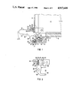
- FIG. 1 shows a cross-section of the present invention
- FIG. 2 shows an embodiment of the end piece of the present invention
- FIG. 3 shows two embodiments of the front plates of present invention
- FIG. 4 shows an additional embodiment of the front plate of the present invention.
- FIG. 5 shows still another embodiment of the present invention using a blind plate.
- a plug-in module carrier is partially depicted, only lower transverse bar 2 being shown for the sake of clarity.
- the carrier serves to receive plug-in modules 4, each module 4 comprising a circuit board with electronic components and contact elements 6 and a front plate 8, front plate 8 facing the front of the carrier.
- Each module 4 is guided into its location in the module carrier by guide rails 10.
- plug-in and pull-out fixtures 12 are arranged at the upper and lower end of each front plate 8.
- a module 4 with Europe format contains only one plug-in and pull-out fixture 12.
- the plug-in and pull-out fixture 12 located at the upper end of module 4 is not shown for the sake of clarity. It is identical with shown fixture 12 and arranged with mirror symmetry.
- Plug-in and pull-out fixture 12 comprises a lever 14 and an end piece 16, end piece 16 being mounted on circuit board 6 via screw 17. Additionally, end piece 16 is connected to front plate 8 in a form - and force-fitting manner by means of screw 18.
- Lever 14 is supported with its axis of rotation 20 perpendicular to the plug-in direction.
- the lever 14 has been shaped as a handle 22 with a self-locking resilient detent hook 24.
- Detent hook 24 extends in the locking position of fixture 12 behind a corresponding projection 26 of slot 28 in end piece 16, the slot opening downwards towards transverse bar 2.
- the inside surface of projection 26 is provided with a predetermined pitch directed toward the bottom of slot 28.
- detent hook 24 The corresponding contact surface of detent hook 24 is shaped in a similar fashion.
- the spring constant is determined by the length of detent hook 24 in conjunction with the material of lever 14.
- This corresponding shape and design of detent hook 24 and projection 26 of slot 28 results in reliable electrical and mechanical coupling of module 4 to the carrier, even in a highly stressed environment.
- this self-locking latch can be unlocked by a motion of the lever 14 in the direction of arrow B without placing excess additional force on detent hook 24.
- Lever 14 of fixture 12 is also provided with slot 30, the edges of which are designated 32 and 34.
- slot 30 of lever 14 engages with projection 36 of slot 37 in transverse bar 2 of the module carrier.
- edge 32 of slot 30 is braced against the outer surface 38 of projection 36.
- Tilting motion of lever 14 in the opposite direction braces inner projection 34 of slot 30 against inside surface 39 of projection 36.
- Inner projection 34 has a slit 40 formed so that the part of inner projection 34 facing away from projection 36 forms resilient leg 42. Due to the elasticity of the material of lever 14 and the shape of slit 40, the entire slot width of slot 37 is filled, whereby lever 14 is cocked in the locking position shown.
- Transverse bar 2 is provided with cavity 44 having a horizontal U - shaped profile, opening towards the front of the module carrier.
- Contact means 46 are arranged over the entire length of cavity 44.
- Contact means 46 takes the form of a leaf spring with comb-like spring tines In the locking position of fixture 12 shown, end piece 16 comes into large-area and, accordingly, low-resistance contact with contact means 46 by means of a tongue-shaped contact area 48 extending parallel to the plug-in direction.
- FIG. 2 shows an advantageous embodiment of end piece 16.
- End piece 16 comprises a tongue-shaped contact area 48, a stop and fastening part 50 for coupling end piece 16 to circuit board 6, slot 28 and fastening device 52 for coupling end piece 16 to front plate 8.
- Contact area 48 is connected to fastening device 62 by means of a connecting piece 54.
- Connecting piece 54 contains a post extending beyond both sides of piece 54, which post serves as the fulcrum of lever 14.
- connecting piece 54 is tapered toward tongue-like contact area 48, surface 56 extending away from contact area 48 at an angle. Surface 56 serves as a support area for lever 14 in its unlocked position.
- Lever 14 is forcibly held in this unlocking position by means of a spring which is attached to end piece 16.
- the inclination of surface 56 is so arranged that, upon inserting module 4 into the module carrier, outer projection 32 of slot 30 comes to lie against outer surface 38 of projection 36, so that lever 14 needs only to be moved in direction of front plate 8 in order to plug-in and lock module 4 in the end position.
- Wall 58 which is opposite to projection 26 of slot 28, and fastening device 52 are arranged parallel to each other at a predetermined spacing so slit 60 is formed.
- Fastening device 52 has shoulder 53 which protrudes into slit 60 and is opposite to wall 58.
- the width of shoulder 53 is smaller than the width of slit 60.
- Wall 58 and fastening device 52 are each provided with tapped holes 62 which are axially aligned.
- Fastening device 52 also has a laterally attached detent hook 64.
- U-shaped front plates 8 whose width is equal to the width of end piece 16 can be connected to this end piece 16 with a positive fit.
- U-shaped front plates whose width is larger that the width of end piece 16 are bolted additionally to end piece 16, connecting front plates 8 to end piece 16 in a form and force-locking manner.
- Front plates 8 of flat material can also be used if they are bolted to end piece 16.
- FIG. 3 shows two different embodiments of the mounting system.
- Plug-in module 41 is provided with a front plate 81 of flat material, the width of which is equal to that of fixture 121.
- Plug-in module 42 is provided with a U-shaped front plate 82, the width of which is twice that of fixture 122.
- the remaining residual width of U-shaped front plate 82 is provided with a cover 68 which can be connected to front plate 82 in a form- and/or force-locking manner.
- Cover 68 is provided with slit 70 which extends perpendicular to the insertion direction.
- Cover 68 is also provided with tongue-shaped area 72 which extends in the insertion direction of plug-in module 42.
- tongue-shaped area 72 extends, when module 42 is plugged in, into cavity 44 of transverse bar 2.
- the height of cover 68 is equal to the spacing of cavity 44 from the lower or upper edge, respectively, of front plate 8 plus the depth of slit 70.
- Cover 68 can be injection molded or extended by the yard, to be cut by the user of the module to the length desired.
- FIG. 4 A further embodiment of the mounting system is shown in FIG. 4.
- the plug-in module 4 has, in addition to components on the component side of the circuit board 6, components on the reverse side 74 of the circuit board. For clarity, only one surface-mounted device (SMD) 76 is shown. Due to the height of the SMD component, the next detent line is reached in the module carrier whereby the width of front plate 8 is greater by one pitch unit TE than fixture 12. This residual width is provided with cover 68. In this manner front plates 8 of any width can be connected to form a front system with a standard fixture 12, the residual width being provided with corresponding cover 68.
- SMD surface-mounted device
- blind plate 78 is plugged into the module carrier.
- Blind plate 76 comprises a U-shaped front plate 8 and two covers 68, the upper cover 68 of blind plate 78 not being shown.
- Cover 68 is connected to front plate 8 in a form - and/or force-fitting manner.
- the width of front plate 8 can be chosen as desired, preferably as a multiple of the base width, referring to the front dimensions of the module carrier in which it is the be used.
- Blind plate 78 covers those parts of the module carrier not occupied by plug-in modules 4.
- Blind plates 78 can also be used to substitute for front plates 8 where the modules 4 have lost their front plates 8.
Abstract
Description
Claims (6)
Applications Claiming Priority (2)
| Application Number | Priority Date | Filing Date | Title |
|---|---|---|---|
| DE8802800U DE8802800U1 (en) | 1988-03-02 | 1988-03-02 | |
| DE8802800[U] | 1988-03-02 |
Publications (1)
| Publication Number | Publication Date |
|---|---|
| US4917618A true US4917618A (en) | 1990-04-17 |
Family
ID=6821359
Family Applications (1)
| Application Number | Title | Priority Date | Filing Date |
|---|---|---|---|
| US07/302,825 Expired - Lifetime US4917618A (en) | 1988-03-02 | 1989-01-26 | Mounting system for plug-in modules |
Country Status (3)
| Country | Link |
|---|---|
| US (1) | US4917618A (en) |
| EP (1) | EP0330957B1 (en) |
| DE (2) | DE8802800U1 (en) |
Cited By (27)
| Publication number | Priority date | Publication date | Assignee | Title |
|---|---|---|---|---|
| US5139430A (en) * | 1990-06-28 | 1992-08-18 | Digital Equipment Corporation | PCB insertion/ejection lever mechanism |
| US5226828A (en) * | 1991-09-23 | 1993-07-13 | Siemens Aktiengesellschaft | Device for unlocking a resiliently prestressed catch element at the side of an insert unit |
| US5316491A (en) * | 1991-07-19 | 1994-05-31 | Kabushiki Kaisha Toshiba | Electronic apparatus, card-type electronic component used with the electronic apparatus, and electronic system with expanding apparatus for expanding function of electronic apparatus |
| US5363281A (en) * | 1990-09-26 | 1994-11-08 | Siemens Nixdorf Informationssysteme Aktiengesellschaft | Device for receiving and locking integrated cards in a support |
| US5504648A (en) * | 1991-09-06 | 1996-04-02 | Kabushiki Kaisha Toshiba | Electronic apparatus and electronic system with expanding apparatus having interlock, ejector, grounding, and lock mechanisms, for expanding function of electronic apparatus |
| US5526227A (en) * | 1991-07-30 | 1996-06-11 | Kabushiki Kaisha Toshiba | Computer having electric conductive portion contacting with electric conductive portion of card, and card receiver device having electric conductive portion contacting with electric conductive portion of card |
| US5544007A (en) * | 1991-07-19 | 1996-08-06 | Kabushiiki Kaisha Toshiba | Card-shaped electronic device used with an electronic apparatus and having shield plate with conductive portion on a lateral side |
| US6208514B1 (en) * | 1998-02-17 | 2001-03-27 | Intel Corporation | Mechanical latch for an electronic cartridge |
| US6220879B1 (en) * | 1998-12-28 | 2001-04-24 | Elma Electric Ag | Plug module with active-passive switching |
| US20010019913A1 (en) * | 1998-08-20 | 2001-09-06 | David J. Llapitan | Retention mechanism for an electrical assembly |
| US6449163B1 (en) | 1998-06-08 | 2002-09-10 | Intel Corporation | Inboard retention system for processor enclosure assemblies with substrate alignment |
| US6515871B1 (en) | 1998-02-17 | 2003-02-04 | Intel Corporation | Protection shield for an electronic cartridge |
| US20030156399A1 (en) * | 2002-02-15 | 2003-08-21 | Cerniglia Sean A. | Integrated bulkhead handle assembly |
| US20040040117A1 (en) * | 2002-09-04 | 2004-03-04 | Purcell Brackets, Inc. | Ejector handle |
| US20040049903A1 (en) * | 2000-08-17 | 2004-03-18 | Werner Koerber | Operating lever with display element |
| US6741479B2 (en) | 1999-12-23 | 2004-05-25 | Rittal Res Electronic Systems Gmbh & Co. Kg | Actuator element for levering in and out printed circuit modules with locking slide, front element for a printed circuit module with actuator element, and subrack that receives printed circuit modules |
| US20040099072A1 (en) * | 2000-08-17 | 2004-05-27 | Werner Koerber | Actuating element comprising a locking element for inserting and removing flat modules by leverage in at least three connection positions, front element for a flat module, comprisng an actuating element and a subassembly support for receiving flat modules |
| US20040219811A1 (en) * | 2003-04-29 | 2004-11-04 | International Business Machines Corporation | Apparatus for positioning an electrical assembly within a housing |
| US7165984B1 (en) * | 1999-12-22 | 2007-01-23 | Rittal Res Electronic Systems Gmbh & Co. Kg | Operating element with on and/or off lever piece for printed circuit boards |
| US20070258224A1 (en) * | 2006-05-04 | 2007-11-08 | Adlink Technology Inc. | Atca locking lever mounting structure |
| US20090000117A1 (en) * | 2005-11-11 | 2009-01-01 | Elma Electronic Ag | Apparatus And Method For The Insertion And Withdrawal Of Plug-In Modules |
| CN100483855C (en) * | 2003-01-31 | 2009-04-29 | 哈廷电子有限公司及两合公司 | Appts. for fixing bullet connector contact parts in bullet connector case |
| US20110299257A1 (en) * | 2010-06-04 | 2011-12-08 | Fujitsu Limited | Insertional buffering structure of substrate unit |
| CN104053331A (en) * | 2014-06-24 | 2014-09-17 | 易力行 | Circuit board secure connection device, circuit board and plug-and-lock industrial personal computer frame |
| US20150135783A1 (en) * | 2013-11-21 | 2015-05-21 | Schneider Electric It Corporation | Locking assembly for securing electronic equipment within an equipment rack |
| US20210364019A1 (en) * | 2020-05-25 | 2021-11-25 | Fivetech Technology Inc. | Fastener structure |
| CN113905576A (en) * | 2021-10-25 | 2022-01-07 | 中国电子科技集团公司第二十九研究所 | Heavy load module with quick locking device |
Families Citing this family (5)
| Publication number | Priority date | Publication date | Assignee | Title |
|---|---|---|---|---|
| FR2681212B1 (en) * | 1991-09-05 | 2004-01-09 | Telecommunications Sa | LOCKING SYSTEM FOR PRINTED CIRCUIT BOARDS. |
| GB9126235D0 (en) * | 1991-12-11 | 1992-02-12 | Bicc Plc | Enclosure for circuit boards |
| DE9301699U1 (en) * | 1993-02-08 | 1993-03-25 | Schroff Gmbh, 7541 Straubenhardt, De | |
| DE50200465D1 (en) † | 2002-02-07 | 2004-06-24 | Schroff Gmbh | Device for inserting and removing a plug-in module |
| DE202015002795U1 (en) | 2015-04-17 | 2016-06-03 | Men Mikro Elektronik Gmbh | Locking device of a plug-in module |
Citations (10)
| Publication number | Priority date | Publication date | Assignee | Title |
|---|---|---|---|---|
| US4233646A (en) * | 1979-06-29 | 1980-11-11 | Northern Telecom Limited | Latching lever for printed circuit boards |
| EP0129833A1 (en) * | 1983-06-22 | 1985-01-02 | Martin W. Oettli | Method of controlling the drift of an anchored ship and apparatus using the method |
| DE3407877A1 (en) * | 1984-03-02 | 1985-09-05 | Siemens AG, 1000 Berlin und 8000 München | Mechanical construction system |
| US4564250A (en) * | 1984-06-22 | 1986-01-14 | Siemens Aktiengesellschaft | Ejection and grounding system for rack-mounted plug-in modules |
| US4602835A (en) * | 1983-06-24 | 1986-07-29 | Siemens Aktiengesellschaft | Ejection and grounding system for rack-mounted plug-in modules |
| US4603375A (en) * | 1985-02-21 | 1986-07-29 | Zero Corporation | Ejector for printed circuit board plug-in unit |
| US4648009A (en) * | 1986-04-09 | 1987-03-03 | Northern Telecom Limited | Articulated latch for use with a printed circuit board |
| US4697303A (en) * | 1985-07-02 | 1987-10-06 | Kitagawa Industries Co., Ltd. | Withdrawal apparatus for a card-like structure |
| US4699594A (en) * | 1985-03-11 | 1987-10-13 | Siemens Aktiengesellschaft | Plug-in and disconnect aid |
| US4783720A (en) * | 1986-03-14 | 1988-11-08 | Schroff Gesellschaft Mit Beschrankter Haftung | Plug assembly |
Family Cites Families (1)
| Publication number | Priority date | Publication date | Assignee | Title |
|---|---|---|---|---|
| EP0129883B1 (en) * | 1983-06-24 | 1989-03-22 | Siemens Aktiengesellschaft | Frontal system for plug-in component boards insertable into frames, and frame for receiving the same |
-
1988
- 1988-03-02 DE DE8802800U patent/DE8802800U1/de not_active Expired
-
1989
- 1989-01-26 US US07/302,825 patent/US4917618A/en not_active Expired - Lifetime
- 1989-02-20 DE DE58907863T patent/DE58907863D1/en not_active Expired - Lifetime
- 1989-02-20 EP EP89102906A patent/EP0330957B1/en not_active Expired - Lifetime
Patent Citations (10)
| Publication number | Priority date | Publication date | Assignee | Title |
|---|---|---|---|---|
| US4233646A (en) * | 1979-06-29 | 1980-11-11 | Northern Telecom Limited | Latching lever for printed circuit boards |
| EP0129833A1 (en) * | 1983-06-22 | 1985-01-02 | Martin W. Oettli | Method of controlling the drift of an anchored ship and apparatus using the method |
| US4602835A (en) * | 1983-06-24 | 1986-07-29 | Siemens Aktiengesellschaft | Ejection and grounding system for rack-mounted plug-in modules |
| DE3407877A1 (en) * | 1984-03-02 | 1985-09-05 | Siemens AG, 1000 Berlin und 8000 München | Mechanical construction system |
| US4564250A (en) * | 1984-06-22 | 1986-01-14 | Siemens Aktiengesellschaft | Ejection and grounding system for rack-mounted plug-in modules |
| US4603375A (en) * | 1985-02-21 | 1986-07-29 | Zero Corporation | Ejector for printed circuit board plug-in unit |
| US4699594A (en) * | 1985-03-11 | 1987-10-13 | Siemens Aktiengesellschaft | Plug-in and disconnect aid |
| US4697303A (en) * | 1985-07-02 | 1987-10-06 | Kitagawa Industries Co., Ltd. | Withdrawal apparatus for a card-like structure |
| US4783720A (en) * | 1986-03-14 | 1988-11-08 | Schroff Gesellschaft Mit Beschrankter Haftung | Plug assembly |
| US4648009A (en) * | 1986-04-09 | 1987-03-03 | Northern Telecom Limited | Articulated latch for use with a printed circuit board |
Cited By (42)
| Publication number | Priority date | Publication date | Assignee | Title |
|---|---|---|---|---|
| US5139430A (en) * | 1990-06-28 | 1992-08-18 | Digital Equipment Corporation | PCB insertion/ejection lever mechanism |
| US5363281A (en) * | 1990-09-26 | 1994-11-08 | Siemens Nixdorf Informationssysteme Aktiengesellschaft | Device for receiving and locking integrated cards in a support |
| US5507661A (en) * | 1991-07-19 | 1996-04-16 | Kabushiki Kaisha Toshiba | Electronic system with expanding apparatus for expanding function of electronic apparatus |
| US5316491A (en) * | 1991-07-19 | 1994-05-31 | Kabushiki Kaisha Toshiba | Electronic apparatus, card-type electronic component used with the electronic apparatus, and electronic system with expanding apparatus for expanding function of electronic apparatus |
| US5499129A (en) * | 1991-07-19 | 1996-03-12 | Kabushiki Kaisha Toshiba | Electronic apparatus having a rib integral with the display housing for protecting the fluorescent lamp |
| US5544007A (en) * | 1991-07-19 | 1996-08-06 | Kabushiiki Kaisha Toshiba | Card-shaped electronic device used with an electronic apparatus and having shield plate with conductive portion on a lateral side |
| US5526227A (en) * | 1991-07-30 | 1996-06-11 | Kabushiki Kaisha Toshiba | Computer having electric conductive portion contacting with electric conductive portion of card, and card receiver device having electric conductive portion contacting with electric conductive portion of card |
| US6172867B1 (en) | 1991-07-30 | 2001-01-09 | Kabushiki Kaisha Toshiba | Electronic apparatus with reinforced upper case |
| US5504648A (en) * | 1991-09-06 | 1996-04-02 | Kabushiki Kaisha Toshiba | Electronic apparatus and electronic system with expanding apparatus having interlock, ejector, grounding, and lock mechanisms, for expanding function of electronic apparatus |
| US5226828A (en) * | 1991-09-23 | 1993-07-13 | Siemens Aktiengesellschaft | Device for unlocking a resiliently prestressed catch element at the side of an insert unit |
| US6208514B1 (en) * | 1998-02-17 | 2001-03-27 | Intel Corporation | Mechanical latch for an electronic cartridge |
| US6515871B1 (en) | 1998-02-17 | 2003-02-04 | Intel Corporation | Protection shield for an electronic cartridge |
| US6449163B1 (en) | 1998-06-08 | 2002-09-10 | Intel Corporation | Inboard retention system for processor enclosure assemblies with substrate alignment |
| US6722908B2 (en) | 1998-08-20 | 2004-04-20 | Intel Corporation | Retention mechanism for an electrical assembly |
| US20030096524A1 (en) * | 1998-08-20 | 2003-05-22 | Llapitan David J. | Retention mechanism for an electrical assembly |
| US6585534B2 (en) | 1998-08-20 | 2003-07-01 | Intel Corporation | Retention mechanism for an electrical assembly |
| US20010019913A1 (en) * | 1998-08-20 | 2001-09-06 | David J. Llapitan | Retention mechanism for an electrical assembly |
| US6220879B1 (en) * | 1998-12-28 | 2001-04-24 | Elma Electric Ag | Plug module with active-passive switching |
| US7165984B1 (en) * | 1999-12-22 | 2007-01-23 | Rittal Res Electronic Systems Gmbh & Co. Kg | Operating element with on and/or off lever piece for printed circuit boards |
| US6741479B2 (en) | 1999-12-23 | 2004-05-25 | Rittal Res Electronic Systems Gmbh & Co. Kg | Actuator element for levering in and out printed circuit modules with locking slide, front element for a printed circuit module with actuator element, and subrack that receives printed circuit modules |
| US7142432B2 (en) * | 2000-08-17 | 2006-11-28 | Rittal Electronic Systems Gmbh & Co. Kg | Operating lever with display element |
| US20040049903A1 (en) * | 2000-08-17 | 2004-03-18 | Werner Koerber | Operating lever with display element |
| US20040099072A1 (en) * | 2000-08-17 | 2004-05-27 | Werner Koerber | Actuating element comprising a locking element for inserting and removing flat modules by leverage in at least three connection positions, front element for a flat module, comprisng an actuating element and a subassembly support for receiving flat modules |
| US6924430B2 (en) * | 2000-08-17 | 2005-08-02 | Rittal Electronics Systems Gmbh & Co. Kg | Actuating element comprising a locking element for inserting and removing flat modules by leverage in a least three connection positions, front element for a flat module, comprising an actuating element and a subassembly support for receiving flat modules |
| US20030156399A1 (en) * | 2002-02-15 | 2003-08-21 | Cerniglia Sean A. | Integrated bulkhead handle assembly |
| US20040040117A1 (en) * | 2002-09-04 | 2004-03-04 | Purcell Brackets, Inc. | Ejector handle |
| CN100483855C (en) * | 2003-01-31 | 2009-04-29 | 哈廷电子有限公司及两合公司 | Appts. for fixing bullet connector contact parts in bullet connector case |
| US20040219811A1 (en) * | 2003-04-29 | 2004-11-04 | International Business Machines Corporation | Apparatus for positioning an electrical assembly within a housing |
| US6884096B2 (en) * | 2003-04-29 | 2005-04-26 | International Business Machines Corporation | Apparatus for positioning an electrical assembly within a housing |
| US8322034B2 (en) * | 2005-11-11 | 2012-12-04 | Elma Electronics Ag | Apparatus and method for the insertion and withdrawal of plug-in modules |
| US20090000117A1 (en) * | 2005-11-11 | 2009-01-01 | Elma Electronic Ag | Apparatus And Method For The Insertion And Withdrawal Of Plug-In Modules |
| US20070258224A1 (en) * | 2006-05-04 | 2007-11-08 | Adlink Technology Inc. | Atca locking lever mounting structure |
| US7301778B1 (en) * | 2006-05-04 | 2007-11-27 | Adlink Technology, Inc. | ATCA locking lever mounting structure |
| US20110299257A1 (en) * | 2010-06-04 | 2011-12-08 | Fujitsu Limited | Insertional buffering structure of substrate unit |
| US8325487B2 (en) * | 2010-06-04 | 2012-12-04 | Fujitsu Limited | Insertional buffering structure of substrate unit |
| US20150135783A1 (en) * | 2013-11-21 | 2015-05-21 | Schneider Electric It Corporation | Locking assembly for securing electronic equipment within an equipment rack |
| US9743549B2 (en) * | 2013-11-21 | 2017-08-22 | Schneider Electric It Corporation | Locking assembly for securing electronic equipment within an equipment rack |
| CN104053331A (en) * | 2014-06-24 | 2014-09-17 | 易力行 | Circuit board secure connection device, circuit board and plug-and-lock industrial personal computer frame |
| CN104053331B (en) * | 2014-06-24 | 2017-01-18 | 陈艺嫔 | Circuit board secure connection device, circuit board and plug-and-lock industrial personal computer frame |
| US20210364019A1 (en) * | 2020-05-25 | 2021-11-25 | Fivetech Technology Inc. | Fastener structure |
| CN113905576A (en) * | 2021-10-25 | 2022-01-07 | 中国电子科技集团公司第二十九研究所 | Heavy load module with quick locking device |
| CN113905576B (en) * | 2021-10-25 | 2023-02-21 | 中国电子科技集团公司第二十九研究所 | Heavy load module with quick locking device |
Also Published As
| Publication number | Publication date |
|---|---|
| EP0330957A1 (en) | 1989-09-06 |
| DE58907863D1 (en) | 1994-07-21 |
| DE8802800U1 (en) | 1988-06-01 |
| EP0330957B1 (en) | 1994-06-15 |
Similar Documents
| Publication | Publication Date | Title |
|---|---|---|
| US4917618A (en) | Mounting system for plug-in modules | |
| US4648009A (en) | Articulated latch for use with a printed circuit board | |
| US4712848A (en) | Edge board connector with positive board lock | |
| EP0528259B1 (en) | Electrical connector with improved latch mechanism | |
| EP0681349A1 (en) | Card edge connector having positive lock and extractor | |
| US4993956A (en) | Active electrical connector | |
| KR970004220B1 (en) | Printed circuit board mounting device for electrical connectors | |
| KR100251116B1 (en) | Connector | |
| EP0445263B1 (en) | Edge connector with board latching devices | |
| US6733344B2 (en) | Electronic device housing | |
| US5842886A (en) | Plug receiving connector | |
| KR20020040558A (en) | Connector for printed circuit boards | |
| EP0582935A1 (en) | Mounting system for electrical connectors | |
| EP0147092B1 (en) | High density low profile multiple contact connector | |
| EP1674606B1 (en) | Door locking device, in particular for a domestic electrical appliance | |
| US6210225B1 (en) | Electrical connector with a pick-up cover | |
| JP2002504757A (en) | Rack device for inserting printed boards | |
| JPH04504926A (en) | plug piece | |
| US6123580A (en) | Board lock for an electrical connector | |
| US6755686B2 (en) | Plug-in connection | |
| US6205033B1 (en) | Electronic assembly circuit board guide apparatus | |
| AU2002254952B2 (en) | Mounting tray for IDC junction modules | |
| AU2002254952A1 (en) | Mounting tray for IDC junction modules | |
| US6135825A (en) | Connector for detachable fastening to a rail | |
| US6575790B2 (en) | Detachable connecting system |
Legal Events
| Date | Code | Title | Description |
|---|---|---|---|
| AS | Assignment |
Owner name: SIEMENS AKTIENGESELLSCHAFT, GERMANY Free format text: ASSIGNMENT OF ASSIGNORS INTEREST.;ASSIGNORS:BEHRENS, RALF;SCHAFFER, KURT-MICHAEL;SCHIERREICH, HELMUT;REEL/FRAME:005034/0821 Effective date: 19891212 |
|
| STCF | Information on status: patent grant |
Free format text: PATENTED CASE |
|
| FEPP | Fee payment procedure |
Free format text: PAYOR NUMBER ASSIGNED (ORIGINAL EVENT CODE: ASPN); ENTITY STATUS OF PATENT OWNER: LARGE ENTITY |
|
| FPAY | Fee payment |
Year of fee payment: 4 |
|
| FPAY | Fee payment |
Year of fee payment: 8 |
|
| AS | Assignment |
Owner name: RITTAL ELECTRONIC SYSTEMS GMBH & CO. KG, GERMANY Free format text: ASSIGNMENT OF ASSIGNORS INTEREST;ASSIGNOR:SIEMENS AKTIENGESELLSCHAFT;REEL/FRAME:011967/0539 Effective date: 20010223 |
|
| FPAY | Fee payment |
Year of fee payment: 12 |