US4924463A - Data coding method for use in digital communication systems - Google Patents
Data coding method for use in digital communication systems Download PDFInfo
- Publication number
- US4924463A US4924463A US07/383,439 US38343989A US4924463A US 4924463 A US4924463 A US 4924463A US 38343989 A US38343989 A US 38343989A US 4924463 A US4924463 A US 4924463A
- Authority
- US
- United States
- Prior art keywords
- bit
- data stream
- words
- group
- symbols
- Prior art date
- Legal status (The legal status is an assumption and is not a legal conclusion. Google has not performed a legal analysis and makes no representation as to the accuracy of the status listed.)
- Expired - Lifetime
Links
Images


Classifications
-
- H—ELECTRICITY
- H04—ELECTRIC COMMUNICATION TECHNIQUE
- H04L—TRANSMISSION OF DIGITAL INFORMATION, e.g. TELEGRAPHIC COMMUNICATION
- H04L25/00—Baseband systems
- H04L25/38—Synchronous or start-stop systems, e.g. for Baudot code
- H04L25/40—Transmitting circuits; Receiving circuits
- H04L25/49—Transmitting circuits; Receiving circuits using code conversion at the transmitter; using predistortion; using insertion of idle bits for obtaining a desired frequency spectrum; using three or more amplitude levels ; Baseband coding techniques specific to data transmission systems
- H04L25/4906—Transmitting circuits; Receiving circuits using code conversion at the transmitter; using predistortion; using insertion of idle bits for obtaining a desired frequency spectrum; using three or more amplitude levels ; Baseband coding techniques specific to data transmission systems using binary codes
- H04L25/4908—Transmitting circuits; Receiving circuits using code conversion at the transmitter; using predistortion; using insertion of idle bits for obtaining a desired frequency spectrum; using three or more amplitude levels ; Baseband coding techniques specific to data transmission systems using binary codes using mBnB codes
-
- H—ELECTRICITY
- H04—ELECTRIC COMMUNICATION TECHNIQUE
- H04J—MULTIPLEX COMMUNICATION
- H04J3/00—Time-division multiplex systems
- H04J3/02—Details
- H04J3/06—Synchronising arrangements
- H04J3/0602—Systems characterised by the synchronising information used
- H04J3/0605—Special codes used as synchronising signal
Definitions
- the present invention relates, in general, to a data coding technique for use with a digital communication system, such as a serial baseband data link.
- coding schemes are often employed to improve the reliability, efficiency, and fault tolerance of the data transmission.
- coding schemes can be employed to aid in the synchronization of the data transmission and reception. Examples of such coding techniques are Manchester, Biphase and delay modulation.
- the Manchester code does, however, provide a constant 50 percent duty cycle, where the duty cycle is defined as the ratio of the number of 1's in a data stream, to the total number of bits in the data stream.
- Control of the duty cycle is desirable for a number of reasons. For one thing, signal variances that may occur in the transmission medium from cable losses, or transmitter strength, for example, affect the signal strength at the receiver. If the duty cycle is relatively fixed, it is easier to pinpoint and compensate for these losses, and compensation can be achieved with simpler circuitry. Simpler circuitry in turn enables the transmission circuit to run at a higher bit rate, which reduces transmission cost and time.
- the present invention is an improved digital data coding method, which provides high efficiency control over the duty cycle and a plurality of dual purpose synchronizing words.
- one embodiment of the invention provides plural data channels.
- a 4B/1/6B is provided which, like the Sperry 4B/5B code, maps every four bits of data into a five bit code symbol (but with a different map).
- a second logical channel is provided which is composed of single bits that are placed after each five bit symbol (every sixth bit of the data stream).
- the data on the second channel can be arbitrarily selected as desired and can include, for example, information from additional communication sources, or control information between the various elements of a communication system.
- the 4B/1/6B code additionally includes a plurality of twelve bit out-of-band synchronizing words that are useful in establishing and maintaining the synchronization of a communication link.
- Each of these synchronizing words includes a pair of five bit symbols which are selected from the sixteen out-of-band five bit symbols that do not correspond to one of the sixteen possible four bit data words.
- the selection of the pairs of out-of-band symbols is such that the resulting bit sequences can only occur where they are placed in a data stream even when the symbol boundaries are not known. Thus, they are easily recognizable by computer circuitry, and so can be used for synchronization of a receiver with an incoming data stream.
- the versatility of the present coding method is substantially increased.
- the synchronizing words can also be utilized for control information, as well.
- a first of the synchronizing words can be used to initially synchronize a communication link's symbol boundary and control state; a second can be used to indicate that the link is idle; a third can be used to indicate that the link is waiting for a signal transmission; and, a fourth can be inserted into the data stream periodically to insure that synchronization is maintained.
- the efficiency of the 4B/1/6B code is 80 percent for channel one data. Since channel two data is arbitrarily selected, it can be set to an efficiency of 80 percent, which will make the combined efficiency of both channels, also 80 percent.
- the duty cycle of the encoded channel one data ranges between 40 and 60 percent (2 or 3 1's per 5 bit code symbol), and, by setting the duty cycle of the channel two data to be the same, the duty cycle of the combined channel one and two data stream will also be 40 to 60 percent.
- the 4B/1/6B code has the further advantage that the maximum consecutive number of either one's or zero's (run length) in the encoded signal is always limited to at most 5. This limit makes it easier for the receiver to synchronize to the signal and to recover clocking information than if no limit was imposed.
- the second embodiment of the invention is a 4B/5B code likesperry's code, and uses the same group of in-band symbols that the 4B/1/6B code uses. However, only a single channel of data is provided. Since it is a 4B/5B code, it too has an efficiency of 80%. The duty cycle varies between 40% and 60% and its maximum run length is 4 since there is no second channel of data. Unlikesperry's 4B/5B code, this 4B/5B code is a NRZ code (Sperry's is a NRZI code). An NRZ code has the advantage that each bit is independently coded, whereas NRZI code bits are not.
- the present 4B/5B code also has a much larger set of individual synchronizing words and mutually compatible sets of synchronizing words.
- the synchronizing words are formed from pairs of five bit symbols, and each pair includes at least one out-of-band five bit symbol.
- the third embodiment of the invention is a "balanced" 4B/6B code having a fixed 50% duty cycle in which every four bits of data are mapped to a six bit code word.
- This balanced code is advantageous because it allows inexpensive code translation between links which require a 50% duty cycle, and those requiring a 40 to 60% duty cycle.
- the balanced 4B/6B code is derived from the two channel embodiment of the invention by choosing the second channel bits to provide a 50% duty cycle.
- the resulting code is advantageous in that it provides up to 70 synchronizing words. Its efficiency is 66.7%, and its maximum run length is 4 or 5, depending on which of the 70 synchronizing words are used.
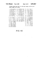
- FIG. 1 is a table showing the five bit in-band code symbols which are used to encode each of sixteen possible four bit data words in the first and second embodiments of the invention
- FIG. 2 is an illustration of a sample data stream encoded in accordance with the first embodiment of the present invention
- FIGS. 3A and 3B are tables illustrating synchronizing words for the first embodiment of the invention that use out-of-band symbol pairs;
- FIGS. 4A and 4B are tables illustrating control words for the first embodiment which are formed from other symbol pairs that can be utilized for miscellaneous control purposes;
- FIG. 5 is a general block diagram of a digital communication system for implementing the disclosed coding methods
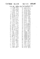
- FIG. 6 is a table of synchronizing words for a second embodiment of the present invention.
- FIGS. 7A and 7B are tables of example sets of mutually compatible synchronizing words selected from the table of FIG. 6;
- FIG. 8 is a table of in-band code symbols for a third embodiment of the present invention.
- FIG. 9 is a table of synchronization words for the third embodiment.
- FIG. 10 is a table of an example set of mutually compatible synchronizing words selected from the table of FIG. 9;
- FIGS. 11A and 11B are tables of control words for the second and third embodiments of the invention, respectively.
- FIG. 1 a table of sixteen five bit in-band code symbols that are utilized to encode each of sixteen possible four bit data words. As shown, there is no particular assignment of these code symbols to the individual data words, and such a selection can be arbitrarily made as desired (the decimal numbers to the left of each entry are for reference purposes only).
- each of them includes either 2 or 3 1's, which means each of the code symbols has a duty cycle (ratio of 1's to total number of bits) of either 40 or 60 percent.
- Being able to pinpoint the cause of signal strength variances enables the communication circuitry to be designed and operated more simply and efficiently, which in turn reduces cost.
- a data transmission having a duty cycle which remains fairly close to 50 percent can be transmitted at a higher bit rate, which saves time, and again, reduces cost.
- FIG. 2 illustrates a sample data stream that is encoded according to a first embodiment of the present invention, which can be termed a 4B/1/6B code.
- the data stream includes two channels (one and two) of data that are interleaved with one another in a time division multiplex manner.
- Channel one data includes five bit encoded symbols from the table in FIG. 1, while channel two includes single bits that are placed in the data stream every six bits, and are marked with an "x" to indicate that any arbitrary choice of a "0" or "1" can be placed at those positions.
- the duty cycle of the code symbols in FIG. 1, and therefore of the channel one data stream varies between 40 and 60 percent.
- the efficiency of the channel one data stream is 80 percent, since every four bit data word is mapped to a five bit code symbol. From this, it is easy to see that the entire data stream can also have a duty cycle of 40 to 60 percent, and an efficiency of 80 percent, if the channel two data is also chosen to meet these criteria. This can easily be accomplished by encoding the channel two data with the same encoding scheme represented in the FIG. 1 table (every four bits of channel two data would be encoded as five bits in accordance with FIG. 1).
- the two channel scheme illustrated in FIG. 2 can serve a number of useful purposes. Often times, a communication link requires more than one channel so that more than one source can transmit data over the same link. In other cases, the second channel is useful for transmitting control information between elements of a communication system without interfering with the data transmission. Examples of such control information include data requests, receiver connection or disconnection, flow control, etc.
- FIG. 3A there is illustrated a table of ten twelve bit synchronizing words for the 4B/1/6B code.
- Each of these synchronizing words includes a pair of out-of-band five bit symbols (out-of-band meaning that they are not in the set of in-band symbols in FIG. 1 that are used for data encoding), and a pair of channel two data bits.
- the channel two bits can be arbitrarily chosen as indicated by the x's placed at the channel two positions in those words.
- These synchronizing words have the property that their bit patterns will only appear, regardless of symbol boundaries, where they are placed in a data steam if they are used individually. This is not necessarily the case, however, if more than one of the ten synchronizing words are placed in a data stream.
- FIG. 3B there is illustrated a subset of four special "mutually compatible" twelve bit synchronizing words that are chosen from the set of FIG. 3A.
- Each of these synchronizing words labeled S1, S2, S3, and S4, are termed "mutually compatible" because they are pairs that result in the synchronizing words having the following unique property. If SW represents any one of the four synchronizing words, then if an encoded data stream is constructed from exactly n occurrences of SW along with an arbitrary number and combination of any or all of the other symbols and symbol pairs from the tables illustrated in FIGS.
- bit pattern SW will occur exactly n times in the resulting encoded string regardless of symbol boundaries.
- S1, S2, S3, and S4 can thus be easily recognized in a data stream and, as will be discussed in further detail below, employed to maintain synchronization of a receiving device with an incoming data stream. Also, the duty cycle of S1 and S2 will remain in the 40 to 60 percent range, regardless of the data on channel two.
- S4 can be utilized to initially synchronize the communication link's symbol boundary and control state. Since the channel two data in S4 is fixed, S4 can be used to reset the state on channel two when channel two is used as a control channel.
- FIGS. 4A and 4B illustrate two groups of other symbol pairs which form control words that can be utilized for miscellaneous communications link control.
- the decimal numbers to the left of each entry in these tables are for reference purposes only.
- the table in FIG. 4A is structured so that the entries in each subgroup have a common left symbol in channel one. These left symbols were selected from out-of-band symbols so that these entries can be easily recognized in a mixed stream of FIG. 1 data symbols.
- the entries in each group in FIG. 4B have been selected for the same reason so that their right symbols in channel one are selected from out-of-band symbols. It is intended that control words be chosen either from FIG. 4A or from FIG. 4B, but not from both.
- FIG. 5 there is illustrated a general block diagram of a communications system and link that employs the present invention.
- a communication system 10 which includes a transmitter and encoder circuit 12.
- Circuit 12 includes a four line input bus 14 for channel one data, which arrives from a source (not shown) in the form of four bit binary words, and is fed to an encoder 16.
- Encoder 16 includes a table lookup ROM or PLA (programmable logic array) for encoding each four bits of data into the corresponding five bit code symbol of FIG. 1.
- encoder 16 Also fed to encoder 16 is the single bit channel two data which arrives on an input line 18.
- a third input is provided to encoder 16 in the form of a multiple line bus 17 so that synchronizing words S1, S2, S3, or S4, along with the control words illustrated in FIG. 4A or 4B, can be passed through encoder 16 for controlling and synchronizing the link.
- the six bit output from encoder 16 is composed of five bit symbols for channel one data, synchronizing words, and control words in addition to the single bit for channel two. It is fed through a six line bus 22 to a parallel to serial converter 24.
- the output from converter 24 is a serial data stream like that shown in FIG. 2, and is transmitted via a serial communication link 26 to a receiver and decoder circuit 28.
- Receiver and decoder circuit 28 includes a serial to parallel converter 30 which reconverts the incoming data stream into six bit words, and feeds them through a six line bus 32 to a decoder 34.
- the data stream arriving on link 26 is also fed to a comparator circuit 36, which monitors a 12 bit wide window of the incoming data to sense the synchronizing words, S1, S2, S3, and S4, that are illustrated in FIG. 3B.
- a start of symbol control output 38 is fed, in response to detection of one of the synchronizing words, from comparator 36 to a sync input 40 on serial to parallel converter 30. This permits the operation of converter 30 to be properly synchronized with the incoming data stream so that it can determine the boundaries between each arriving code symbol.
- An output bus 41 is also provided on comparator 36 for outputting any received synchronizing words to an external device (not shown).
- Decoder 34 like encoder 16, includes a table lookup ROM or PLA to permit the incoming five bit symbols to be reconverted to the original four bit data words, and fed via a four line output bus 42 to a data receiving element (not shown).
- Channel two data is fed through decoder 34 to a single output line 44, and through an optional decoder 46 if the channel two data has been previously encoded, to a data receiving element (not shown).
- Another output bus 48 is provided on decoder 34 for outputting any of the control words in FIG. 4A or 4B that are received. This output is combined with the second output 41 from comparator 36, and can be fed to an external device (not shown) for control and synchronization purposes.
- the second data channel is not employed, and the resulting code is a 4B/5B NRZ code.
- This code utilizes the in-band code symbols of FIG. 1, and up to thirty individual synchronizing words as illustrated in FIG. 6. These thirty synchronizing words can be used individually with any of the in-band code symbols of FIG. 1 and be recognized in the data stream, although they may not necessarily be used in combination with other synchronizing words of FIG. 6.
- FIGS. 7A and 7B two sets of mutually compatible synchronizing words are illustrated, both of which are chosen from FIG. 6 as indicated by the entry numbers.
- the elements of these sets of synchronizing words can be used in combination with each other and have the same properties as the synchronizing words for the 4B/1/6B code illustrated in FIG. 3B. It should be understood that there are numerous other combinations of mutually compatible synchronizing words, and the sets illustrated in FIGS. 7A and 7B represent only two examples of these combinations.
- the in-band code symbols for a third embodiment of the present invention are illustrated in FIG. 8.
- This code is a 4B/6B code and has a balanced 50% duty cycle.
- the code symbols are derived from those of FIG. 1 by simply adding a leading 0 or 1 as needed to make the number of 1's and 0's in each symbol equal.
- the resulting code is a specialization of the 4B/1/6B code where the second channel bit has been set to a specific value for all in-band channel one symbols.
- the 4B/6B balanced code has 70 individual twelve bit synchronizing words which are illustrated in FIG. 9. From this set, a large number of mutually compatible sets of synchronizing words having the same properties of the synchronizing words in FIG. 3 for the 4B/1/6B code can be selected. An example of a mutually compatible set of synchronizing words is illustrated in FIG. 10. The number of synchronizing words in the set of FIG. 10 is larger than that of FIG. 3B because the second channel "x" bits now have specific values. Many other mutually compatible subsets of the FIG. 9 set exist including sets which contain more words than the set of FIG. 10.
- the in-band symbols of FIG. 1 can be used with the following set of mutually compatible synchronizing words from FIG. 7B that are chosen to independently code 2 bits of additional control information, w and v, in a highly redundant manner:
- the w code has Hamming distance 5 which means 3 bit errors within the symbol can be corrected.
- the v code has Hamming distance 3 which means 1 bit errors within the symbol can be corrected.
- out-of-band words can be used for control information without affecting the mutually compatible set properties:
- control words along with a number of other control words that are compatible with this example set of 4B/5B synchronizing words are illustrated in FIG. 11A.
- the in-band symbols of FIG. 8 can be combined with the following mutually compatible synchronizing words chosen from FIG. 10 to also independently code 2 bits of additional code information, w and v, in a highly redundant manner:
- the present invention provides an improved data encoding method which possesses a high efficiency, has good duty cycle control, and is very versatile by virtue of the two channel scheme in the first embodiment, and multiple synchronizing words in all three embodiments that can be employed both for data synchronization and control information transmission.
Abstract
Description
______________________________________ w v Entry # from FIG. 7B ______________________________________ w = 01111 01100 = v 15 w = 01111 00010 =vbar 13 wbar = 10000 11101 =v 18 wbar = 10000 10011 =vbar 16 ______________________________________
______________________________________ Word Information Conveyed ______________________________________ 10111 00100 Start ofPacket 01000 11011 End ofPacket 10111 00010Idle Channel 01000 11101 Pad ______________________________________
______________________________________
w           v       Entry # from FIG. 10
______________________________________
001111      001100  11
001111      100010  14
110000      011101  57
110000      110011  60
______________________________________
______________________________________ Word Information Conveyed ______________________________________ 010111 100100 Start ofpacket 110111 000100 001000 111011 End ofpacket 101000 011011 010111 100010ldle Channel 110111 000010 001000 111101Pad 101000 011101 ______________________________________
Claims (20)
Priority Applications (1)
| Application Number | Priority Date | Filing Date | Title |
|---|---|---|---|
| US07/383,439 US4924463A (en) | 1989-03-02 | 1989-07-24 | Data coding method for use in digital communication systems |
Applications Claiming Priority (2)
| Application Number | Priority Date | Filing Date | Title |
|---|---|---|---|
| US31846389A | 1989-03-02 | 1989-03-02 | |
| US07/383,439 US4924463A (en) | 1989-03-02 | 1989-07-24 | Data coding method for use in digital communication systems |
Related Parent Applications (1)
| Application Number | Title | Priority Date | Filing Date |
|---|---|---|---|
| US31846389A Continuation-In-Part | 1989-03-02 | 1989-03-02 |
Publications (1)
| Publication Number | Publication Date |
|---|---|
| US4924463A true US4924463A (en) | 1990-05-08 |
Family
ID=26981496
Family Applications (1)
| Application Number | Title | Priority Date | Filing Date |
|---|---|---|---|
| US07/383,439 Expired - Lifetime US4924463A (en) | 1989-03-02 | 1989-07-24 | Data coding method for use in digital communication systems |
Country Status (1)
| Country | Link |
|---|---|
| US (1) | US4924463A (en) |
Cited By (13)
| Publication number | Priority date | Publication date | Assignee | Title |
|---|---|---|---|---|
| US5426735A (en) * | 1990-06-11 | 1995-06-20 | Mita Industrial Co., Ltd. | Data communication device capable of adding data identification code to each data byte |
| EP0720318A2 (en) * | 1994-12-27 | 1996-07-03 | Nec Corporation | Time division multiplexing transmitter and decoding circuit multiplexing transmission |
| US5570388A (en) * | 1994-09-27 | 1996-10-29 | Digital Ocean, Inc. | Method and apparatus using simple codes for the wireless transmission of non-data symbols |
| US5606317A (en) * | 1994-12-09 | 1997-02-25 | Lucent Technologies Inc. | Bandwidth efficiency MBNB coding and decoding method and apparatus |
| US5625644A (en) * | 1991-12-20 | 1997-04-29 | Myers; David J. | DC balanced 4B/8B binary block code for digital data communications |
| US20020172200A1 (en) * | 2000-11-22 | 2002-11-21 | Yeshik Shin | Method and system for integrating packet type information with synchronization symbols |
| US6556583B1 (en) * | 1998-02-24 | 2003-04-29 | Yokogawa Electric Corporation | Communication system and communication control method |
| US20050069041A1 (en) * | 2000-10-06 | 2005-03-31 | Lincoln Daniel J. | Coherent expandable high speed interface |
| US20060132335A1 (en) * | 2004-12-20 | 2006-06-22 | Kawasaki Microelectronics, Inc. | Parallel data transmission method and parallel data transmission system |
| US20070088883A1 (en) * | 2005-10-13 | 2007-04-19 | Denso Corporation | Communication system and method, and distributed control system and method |
| US20070147354A1 (en) * | 2005-08-26 | 2007-06-28 | Ziqiang He | Local area network |
| US7676725B1 (en) | 2006-02-27 | 2010-03-09 | The United States Of America As Represented By The Director, National Security Agency | Method of code generation that minimizes error propagation |
| EP2339790A1 (en) * | 2009-12-28 | 2011-06-29 | Nxp B.V. | Definition of wakeup bus messages for partial networking |
Citations (4)
| Publication number | Priority date | Publication date | Assignee | Title |
|---|---|---|---|---|
| US3985967A (en) * | 1975-12-08 | 1976-10-12 | Bell Telephone Laboratories, Incorporated | Common control constant shift reframe circuit |
| US4161719A (en) * | 1977-10-04 | 1979-07-17 | Ncr Corporation | System for controlling synchronization in a digital communication system |
| US4530088A (en) * | 1983-02-15 | 1985-07-16 | Sperry Corporation | Group coding system for serial data transmission |
| US4606056A (en) * | 1985-02-04 | 1986-08-12 | Burroughs Corporation | Method of encoding and serially transmitting self-clocking data and control characters |
-
1989
- 1989-07-24 US US07/383,439 patent/US4924463A/en not_active Expired - Lifetime
Patent Citations (4)
| Publication number | Priority date | Publication date | Assignee | Title |
|---|---|---|---|---|
| US3985967A (en) * | 1975-12-08 | 1976-10-12 | Bell Telephone Laboratories, Incorporated | Common control constant shift reframe circuit |
| US4161719A (en) * | 1977-10-04 | 1979-07-17 | Ncr Corporation | System for controlling synchronization in a digital communication system |
| US4530088A (en) * | 1983-02-15 | 1985-07-16 | Sperry Corporation | Group coding system for serial data transmission |
| US4606056A (en) * | 1985-02-04 | 1986-08-12 | Burroughs Corporation | Method of encoding and serially transmitting self-clocking data and control characters |
Cited By (25)
| Publication number | Priority date | Publication date | Assignee | Title |
|---|---|---|---|---|
| US5426735A (en) * | 1990-06-11 | 1995-06-20 | Mita Industrial Co., Ltd. | Data communication device capable of adding data identification code to each data byte |
| US5625644A (en) * | 1991-12-20 | 1997-04-29 | Myers; David J. | DC balanced 4B/8B binary block code for digital data communications |
| US5570388A (en) * | 1994-09-27 | 1996-10-29 | Digital Ocean, Inc. | Method and apparatus using simple codes for the wireless transmission of non-data symbols |
| US5606317A (en) * | 1994-12-09 | 1997-02-25 | Lucent Technologies Inc. | Bandwidth efficiency MBNB coding and decoding method and apparatus |
| EP0720318A2 (en) * | 1994-12-27 | 1996-07-03 | Nec Corporation | Time division multiplexing transmitter and decoding circuit multiplexing transmission |
| EP0720318A3 (en) * | 1994-12-27 | 1999-04-28 | Nec Corporation | Time division multiplexing transmitter and decoding circuit multiplexing transmission |
| US6556583B1 (en) * | 1998-02-24 | 2003-04-29 | Yokogawa Electric Corporation | Communication system and communication control method |
| US20050069041A1 (en) * | 2000-10-06 | 2005-03-31 | Lincoln Daniel J. | Coherent expandable high speed interface |
| US7746798B2 (en) * | 2000-11-22 | 2010-06-29 | Silicon Image, Inc. | Method and system for integrating packet type information with synchronization symbols |
| US7257129B2 (en) * | 2000-11-22 | 2007-08-14 | Silicon Image | Memory architecture with multiple serial communications ports |
| US20080126824A1 (en) * | 2000-11-22 | 2008-05-29 | Silicon Image, Inc. | Communications architecture for memory-based devices |
| US20020191475A1 (en) * | 2000-11-22 | 2002-12-19 | Dongyun Lee | Communications architecture for memory-based devices |
| US20020172200A1 (en) * | 2000-11-22 | 2002-11-21 | Yeshik Shin | Method and system for integrating packet type information with synchronization symbols |
| US7903684B2 (en) | 2000-11-22 | 2011-03-08 | Silicon Image, Inc. | Communications architecture for transmission of data between memory bank caches and ports |
| US20060132335A1 (en) * | 2004-12-20 | 2006-06-22 | Kawasaki Microelectronics, Inc. | Parallel data transmission method and parallel data transmission system |
| US7307554B2 (en) | 2004-12-20 | 2007-12-11 | Kawasaki Microelectronics, Inc. | Parallel data transmission method and parallel data transmission system |
| US9106427B2 (en) * | 2005-08-26 | 2015-08-11 | Ziqiang He | Local area network |
| US20070147354A1 (en) * | 2005-08-26 | 2007-06-28 | Ziqiang He | Local area network |
| US20070088883A1 (en) * | 2005-10-13 | 2007-04-19 | Denso Corporation | Communication system and method, and distributed control system and method |
| US7487266B2 (en) * | 2005-10-13 | 2009-02-03 | Denso Corporation | Communication system and method, and distributed control system and method |
| US7676725B1 (en) | 2006-02-27 | 2010-03-09 | The United States Of America As Represented By The Director, National Security Agency | Method of code generation that minimizes error propagation |
| WO2011080662A1 (en) * | 2009-12-28 | 2011-07-07 | Nxp B.V | Definition of wakeup bus messages for partial networking |
| CN102687471A (en) * | 2009-12-28 | 2012-09-19 | Nxp股份有限公司 | Definition of wakeup bus messages for partial networking |
| US9032124B2 (en) | 2009-12-28 | 2015-05-12 | Nxp B.V. | Definition of wakeup bus messages for partial networking |
| EP2339790A1 (en) * | 2009-12-28 | 2011-06-29 | Nxp B.V. | Definition of wakeup bus messages for partial networking |
Similar Documents
| Publication | Publication Date | Title |
|---|---|---|
| EP0556981B1 (en) | Method and apparatus for transmitting and receiving code | |
| US4924463A (en) | Data coding method for use in digital communication systems | |
| US6167077A (en) | Using multiple high speed serial lines to transmit high data rates while compensating for overall skew | |
| US5408473A (en) | Method and apparatus for transmission of communication signals over two parallel channels | |
| EP0977411B1 (en) | Block code with limited disparity | |
| US5614901A (en) | Method and apparatus for providing data stream for cost effective transmission links | |
| US5420583A (en) | Fiber optic channel extender interface method and apparatus | |
| JPH07226730A (en) | Data transmission system | |
| US7889763B2 (en) | Data transmission apparatus and data transmission method | |
| GB2110509A (en) | Apparatus for and methods of processing digital data | |
| EP0886407B1 (en) | 5B6B coding for split channel transmission | |
| US5144305A (en) | Transmission arrangement comprising a block code encoded main channel and an auxiliary channel | |
| US5790057A (en) | Method of and system for the efficient encoding of data | |
| US5144469A (en) | Method for the transmission of data between two stations by means of optical waveguides | |
| WO2003075495A2 (en) | Multiplexing an additional bit stream with a primary bit stream | |
| EP0355988A2 (en) | Method and apparatus for transmitting and receiving characters using a balanced weight error correcting code | |
| US5428611A (en) | Strong framing protocol for HDLC and other run-length codes | |
| US5034741A (en) | Variable length bit patterns for data representation | |
| AU716212B2 (en) | Time multiplexing/demultiplexing method | |
| JPH03297236A (en) | Data transmission system | |
| JPH0936823A (en) | Parallel data transmitter using mbnb code | |
| US6356596B1 (en) | Encoding and decoding method using a multi-state signal | |
| JPH0377695B2 (en) | ||
| RU2206181C1 (en) | Data coding/decoding device | |
| CN1404674A (en) | Information processing system |
Legal Events
| Date | Code | Title | Description |
|---|---|---|---|
| AS | Assignment |
Owner name: DIGITAL EQUIPMENT CORPORATION, MASSACHUSETTS Free format text: ASSIGNMENT OF ASSIGNORS INTEREST.;ASSIGNORS:THOMAS, ROBERT E.;COOPER, JEFFREY L.;SIMCOE, ROBERT J.;REEL/FRAME:005182/0980;SIGNING DATES FROM 19891106 TO 19891113 |
|
| STCF | Information on status: patent grant |
Free format text: PATENTED CASE |
|
| FEPP | Fee payment procedure |
Free format text: PAYOR NUMBER ASSIGNED (ORIGINAL EVENT CODE: ASPN); ENTITY STATUS OF PATENT OWNER: LARGE ENTITY |
|
| FPAY | Fee payment |
Year of fee payment: 4 |
|
| FPAY | Fee payment |
Year of fee payment: 8 |
|
| AS | Assignment |
Owner name: CABLETRON SYSTEMS, INC., NEW HAMPSHIRE Free format text: ASSIGNMENT OF ASSIGNORS INTEREST;ASSIGNOR:DIGITAL EQUIPMENT CORPORATION;REEL/FRAME:009046/0792 Effective date: 19980206 |
|
| AS | Assignment |
Owner name: ENTERASYS NETWORKS, INC., NEW HAMPSHIRE Free format text: ASSIGNMENT OF ASSIGNORS INTEREST;ASSIGNOR:CABLETRON SYSTEMS, INC.;REEL/FRAME:011219/0376 Effective date: 20000929 |
|
| FEPP | Fee payment procedure |
Free format text: PAYER NUMBER DE-ASSIGNED (ORIGINAL EVENT CODE: RMPN); ENTITY STATUS OF PATENT OWNER: LARGE ENTITY Free format text: PAYOR NUMBER ASSIGNED (ORIGINAL EVENT CODE: ASPN); ENTITY STATUS OF PATENT OWNER: LARGE ENTITY |
|
| FPAY | Fee payment |
Year of fee payment: 12 |
|
| AS | Assignment |
Owner name: OBSIDIAN, LLC, CALIFORNIA Free format text: SECURITY AGREEMENT;ASSIGNOR:ENTERASYS NETWORKS, INC.;REEL/FRAME:017656/0552 Effective date: 20060516 Owner name: WELLS FARGO FOOTHILL, INC., CALIFORNIA Free format text: SECURITY AGREEMENT;ASSIGNOR:ENTERASYS NETWORKS, INC.;REEL/FRAME:017656/0552 Effective date: 20060516 |
|
| AS | Assignment |
Owner name: ENTERASYS NETWORKS, INC., MASSACHUSETTS Free format text: RELEASE AND REASSIGNMENT OF PATENTS AND PATENT APPLICATIONS AT REEL/FRAME NO. 17656/0552;ASSIGNORS:WELLS FARGO CAPITAL FINANCE, INC. (FORMERLY KNOWN AS WELLS FARGO FOOTHILL, INC.);ENTERPRISE COMMUNICATIONS FUNDING GMBH, AS SUCCESSOR IN INTEREST TO OBSIDIAN, LLC;REEL/FRAME:025406/0769 Effective date: 20101110 |