US4930101A - Microprocessor-controlled meter package for a printer - Google Patents
Microprocessor-controlled meter package for a printer Download PDFInfo
- Publication number
- US4930101A US4930101A US06/861,527 US86152786A US4930101A US 4930101 A US4930101 A US 4930101A US 86152786 A US86152786 A US 86152786A US 4930101 A US4930101 A US 4930101A
- Authority
- US
- United States
- Prior art keywords
- power
- meter
- printer
- kilolines
- hours
- Prior art date
- Legal status (The legal status is an assumption and is not a legal conclusion. Google has not performed a legal analysis and makes no representation as to the accuracy of the status listed.)
- Expired - Fee Related
Links
Images


Classifications
-
- B—PERFORMING OPERATIONS; TRANSPORTING
- B41—PRINTING; LINING MACHINES; TYPEWRITERS; STAMPS
- B41J—TYPEWRITERS; SELECTIVE PRINTING MECHANISMS, i.e. MECHANISMS PRINTING OTHERWISE THAN FROM A FORME; CORRECTION OF TYPOGRAPHICAL ERRORS
- B41J29/00—Details of, or accessories for, typewriters or selective printing mechanisms not otherwise provided for
- B41J29/20—Arrangements of counting devices
-
- B—PERFORMING OPERATIONS; TRANSPORTING
- B41—PRINTING; LINING MACHINES; TYPEWRITERS; STAMPS
- B41J—TYPEWRITERS; SELECTIVE PRINTING MECHANISMS, i.e. MECHANISMS PRINTING OTHERWISE THAN FROM A FORME; CORRECTION OF TYPOGRAPHICAL ERRORS
- B41J35/00—Other apparatus or arrangements associated with, or incorporated in, ink-ribbon mechanisms
- B41J35/36—Alarms, indicators, or feed disabling devices responsive to ink ribbon breakage or exhaustion
Definitions
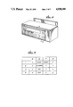
- FIG. 4 shows a pictorial representation of the 16-character alpha-numeric display and membrane keypad switch panel, both previously seen in FIG. 2, of the present invention.
- the program allows flexibility of the microprocessor-controlled meter package and enables display of customized alphanumeric messages.
- currently unused function keys F1, F2, and F3 allow implementation of specific customer requirements or future enhancements.
- Possible enhancements to the functions performed by the present invention include (1) the calculation of the printer duty cycle as the PRINT HOURS time divided by the total printer HOURS ON time, (2) the remaining hours until a service call is required, (3) the number of printer faults, and/or (4) the number of printer faults causing or requiring power down.
- the present approach offers more information, English language messages and prompts, better accuracy, and cost reduction over prior art methods of displaying status within, and cumulative operations of, a line printer. Consequent to such flexible and efficient application in serving as the meter package for a printer, the present invention should be interpreted by those claims which follow, only, and not by the specific preferred embodiment, either hardware or software, within which such invention is taught.
Abstract
In a line printer, an integrated meter package developing a clock incorporates a microprocessor receiving a line printed signal, power on voltage, and a preset ribbon exhaust count in order to compute in reference to the clock, and selectively display on an alphanumeric display panel, the total the lines printed, total on hours, total print hours, preset ribbon exhaust count, and number of print lines remaining until exhaustion of the ribbon. The microprocessor stores accumulated values to a non-volatile electrically programmable memory upon receipt of a power going down signal warning of incipient power off. The microprogrammed control is adaptable to maintain general maintenance and fault histories and periods.
Description
1. Field of the Invention
The present invention is generally concerned with electronically metering the histories and periods relevant to the maintenance and use of a printer. The present invention is specifically controlled using a microprocessor to receive certain signals, and to calculate and display certain quantities, particularly concerned with activities within a line printer.
2. Description of the Prior Art
Microprocessor-based control and maintenance panels, sometimes of great sophistication, are known for use with computers. However, metering, or conditions display for printers calls for the accumulation, and display, of certain types of information which are alien to computers.
One such condition which can be metered and displayed for a line printer is the total number of lines printed. In the prior art, such metering of total lines printed was accomplished by a mechanical or by an electrical-mechanical counter.
Another quantity which can be monitored for line printers is the remaining number of hours, or lines, within the life of a replaceable ribbon. This was also accomplished in the prior art by a mechanical or by an electrical-mechanical counter. Such electrical-mechanical counter could either be preset to a fixed number and count down, or, alternatively, could be preset to zero and count up. Both the counters for lines printed and for remaining lines of ribbon life tended to be bulky, expensive and failure prone.
Additionally, prior art printers normally employed an analog "mercury", thermometer-type, powered-on hours indicator. Such indicators are based on the migration of a visual indicator, nominally mercury, through a media during the presence of a potential difference across such media during periods of printer power on. Upon such elapsed hours as the migrating substance has completely crossed the media, the meter scale may be reversed, or the applied voltage may be reversed, and the entire process engaged in in the reverse direction. Unfortunately, the indication of elapsed hours obtained from such devices is extremely crude.
There is no evident attempt in the prior art to accumulate total print hours, possibly because of such crudity of elapsed time indicators. Consequent to the failure to determine total print hours, the duty cycle during which the printer is actually printing, as a fraction of the total hours during which the printer is powered on, has been indeterminable.
The present invention is a comprehensive, microprocessor-based, integrated meter package particularly for a line printer. The meter package will receive a line printed signal and power on voltage from the printer, and the user can manually enter a preset ribbon exhaust count. It internally produces a reference clock signal. The meter package computes therefrom, and selectively displays on an alphanumeric display panel, the (1) total lines printed, (2) total power-on hours, (3) total print hours, (4) ribbon exhaust preset, and (5) number of lines remaining in the current ribbon life. The meter package contains a microprocessor. Control of the microprocessor is by microcode, which is tailored in the preferred embodiment of the invention to a line printer but which is adaptable to diverse printer types. The microprogram approach offers improved English language prompts and output communication, better accuracy and resolution of quantities derived, and a cost reduction over prior art systems. It additionally offers the intrinsic display of new (the total print hours) and more accurate (the total power-on hours) information. Quantities hithertofore undeterminable such as the printer duty cycle (equalling the total print hours divided by the total power-on hours) are accurately determinable from the display output of the microprocessor-controlled meter package of the present invention.
In particular implementation, the present invention uses a microprocessor with both an integrated, on-board, random access memory (RAM) and read only memory (ROM), a 16-character alpha-numeric display, a non-volatile electrically erasable programmable read-only memory (EEPROM), and an 8-position membrane keypad. Multiple functions are accessible from the keypad, and data such as the ribbon life preset may be entered. The microprocessor uses its on-board random access memory (RAM) during power-on time for the storage of operands. The micro-instructions are nonvolatilely stored in the on-board read only memory (ROM). When the printer's power supply is cut off, a rapidly dropping printer-developed signal is sensed by the microprocessor some milliseconds before the D.C. supply voltage used to power the meter logic becomes unusable. The microprocessor then preserves computed operands in the RAM memory to the EEPROM (which has a limited write cycle life). The contents of the EEPROM are reloaded to RAM on power-up, and the system is totally reactivated for accruing the metered quantities. Displayed resolution of all time quantities maintained is to the hour, and all counts maintained are precise.
Correspondingly, it is the object of the present invention to employ a microprocessor-based integrated meter package for the metering of certain quantities, and elapsed times, particularly pertinent to the operation of a printer.
FIG. 1 shows a representational diagram of the location and function of the present invention of a microprocessor-controlled meter package for a printer.
FIG. 2 shows a schematic block diagram of the microprocessor-controlled meter package for a printer of the present invention.
FIG. 3 shows a timing diagram of certain signals of the printer which are communicated to and from the circuit of the present invention shown in FIG. 2.
FIG. 4 shows a pictorial representation of the 16-character alpha-numeric display and membrane keypad switch panel, both previously seen in FIG. 2, of the present invention.
FIG. 5 shows a matrix indicating how actuation of those membrane switches, shown in the pictorial representation of the display of FIG. 4, translate into control signals received at the microprocessor previously seen in FIG. 2.
The present invention of a microprocessor-controlled meter package for a printer accumulates and displays certain status and use information involved with the activities of a line printer. In prior art printers, the total number of lines printed within a line printer, and the number of lines printed since the replacement of the ribbon (or, alternatively, the number of lines remaining in a preset ribbon count which is decremented with each line printed) were, insofar as such quantities were registered at all, maintained by mechanical or electrical-mechanical counters. The number of power-on hours (which will be maintained by the meter package of the present invention) was maintained in prior art printers by "thermometer-type" analog gauges reading, as a crude indication of elapsed time, the visual migration of a chemical indicia across a barrier of some width due to the presence during power on of a power voltage which induces migration of the indicia across the barrier. The physical displacement of the indicia within the barrier is a rough indication of elapsed power on time. By contrast, the present invention will maintain the total printer-on hours (HOURS ON) with high accuracy, and will additionally maintain the total number of hours during which the printer actually prints (PRINT HOURS). From these two quantities, the duty cycle of use of the printer can be derived as the total print hours divided by the total hours on.
A representational diagram of the present invention is shown in FIG. 1. An integrated METER PACKAGE 1 is completely contained within an otherwise conventional LINE PRINTER which is correspondingly illustrated in dashed line. A MICROPROCESSOR 2 is for receiving CONTROL AND DATA signals from a manual SWITCH PANEL 6, and signals indicating LINE PRINTED and POWER ON from the LINE PRINTER, plus a POWER GOING DOWN signal when the printer's power supply is cut off. A CLOCK signal is internally developed in METER PACKAGE 1, such as in the microprocessor. From these control, data, and input signals and by reference to the clock signal the MICROPROCESSOR 2 CALCULATES the counter variables (1) HOURS ON, (2) PRINT HOURS, (3) PRINTED LINES, and (4) REMAINING RIBBON LIFE. These quantities and others are displayed on an ALPHANUMERIC DISPLAY 12, in a prestored format which offers ENGLISH LANGUAGE MESSAGES & PROMPTS. The entire function is controlled by microcode.
A schematic block diagram of the apparatus of the present invention is shown in FIG. 2. The MICROPROCESSOR 2 receives certain power, ground, and sensor signals via a plug 4 embedded in the printer. The MICROPROCESSOR 2 also receives input signals from an external SWITCH PANEL via a cable having a plug 8. The MICROPROCESSOR 2 engages in bidirectional communication for the reading and writing of data with a 16×16 NONVOLATILE EEPROM 10. To output the computed meter readings the MICROPROCESSOR 2 transmits the codes for 16 characters of corresponding alpha-numeric information for display on a 16 CHARACTER ALPHA-NUMERIC DISPLAY 12 connected by cable via a plug 14. Also upon its bussed communication channel, the MICROPROCESSOR 2 uses its on-board random access memory (RAM) for the storage of operands, such as the counter variables. The MICROPROCESSOR 2 uses its on-board read only memory (ROM) for the storage of microinstructions. Finally, the microprocessor produces a RIBBON EXHAUSTED signal which is communicated to an indicator within the printer via an alarm line connecting through a pin 2 of printer plug 4. Normally, the MICROPROCESSOR 2 and associated components illustrated inboard of plugs 4, 8, and 14 are entirely implemented upon a single printed circuit card.
Continuing in FIG. 2, the MICROPROCESSOR 2 is flexibly controlled by a microprogram prestored within its on-board read only memory (ROM). For nonvolatile storage of variables MICROPROCESSOR 2 also communicates with a second random access memory in the form of a 16×16 electrically erasable programmable memory, EEPROM 10. Compared to the RAM memory, this EEPROM has a limited write cycle life. After printer power is restored, the program contents within such memory are transferred back by the MICROPROCESSOR 2 to its on-board random access memory (RAM) and the operands stored in such random access memory (RAM) are used for the duration of the power-on condition. Responsive to an imminent power loss condition at the printer, a POWER GOING DOWN signal is received on plug 4, pin 5. The MICROPROCESSOR 2 will write the contents of its onboard random access memory (RAM), including all accumulated meter readings, to the 16×16 NONVOLATILE EEPROM 10. In particular, the total lines printed (in kilolines) and total hours on operand quantities will be stored. This activity upon the detection of an imminent power loss eliminates the need for battery backup of the on-board random access memory (RAM), for which the contents are volatile during power outage.
The function of MICROPROCESSOR 2 so executing such microprogram contained within the on-board read only memory (ROM) is to interpret user commands which are entered through manual SWITCH PANEL 6, to maintain certain accumulations of status and use conditions of the printer, and to display selected status or accumulated use totals as output alpha-numeric displays on the 16 CHARACTER ALPHANUMERIC DISPLAY 12. In particular, the microprocessor-executed program will cause the panel display to automatedly scroll through the following messages designated A-E at approximately 2-second intervals:
A XXXXX HOURS ON
B XXXXX PRINT HRS
C XXXXX K LINES
D X X X K LINES LEFT (or if the ribbon is exhausted then display: RIBBON EXHAUSTED)
E PRESET=X X X K (or if preset=0 then display: NO RIBBON PRESET)
A Mode switch (shown in FIG. 4) within the 8-position membrane keypad which serves as SWITCH PANEL 16 will, when pressed, cause the scrolling of the display to stop and will maintain the display of the current mode for 10 seconds. If the Mode switch is again depressed within the 10-second interval, then the next occurring status message will be displayed.
In all the messages A-E illustrated above, the character "X" is replaced with an appropriate actual digit. Message A is the microprocessor-calculated number of power on hours, which is derived from maintaining an HOURS ON counter variable responsive to a 12 megahertz internal clock signal shown in FIG. 2 to be regulated by a 12 MHz crystal connected at pins 18 and 19. Appendix A is an assembly program that includes steps enabling an Intel 8051 microprocessor to calculate HOURS ON using an onboard timer (TIMER1) driven by the microprocessor's clock pulses. A SET-- TIMER1 routine (lines 910-16) set TIMER 1 to interrupt the microprocessor every 50 ms as long as the POWER ON signal is high. In a corresponding TIMER1-- INT interrupt handler, twenty such interrupts decrement a SECOND COUNTER (lines 160, 862-876), and sixty decrements of SECOND decrement a MINUTE counter (lines 162, 876-79). Sixty decrements of MINUTE increment (lines 879-884) a two byte hours counter (HOUR -- 2, HOUR-- 1) that holds the HOURS ON value.
Message B is the microprocessor-calculated number of PRINT HOURS which is derived by updating a PRINT HOURS counter variable from the clock only during periods when the LINE PRINTED signal has changed level (meaning a line has been printed) within a suitably preselected proximate time interval, nominally 1 second. The assembly program of Appendix A also uses the TIMER1-- INT interrupt handler to calculate PRINT HOURS. Each time the SECOND counter is decremented, a P-- SECOND counter ("line printed" seconds) is also afterwards decremented (line 888), provided a PRINT FLAG bit is set (line 886). Sixty decrements of P-- SECOND decrement a P-- MINUTE counter, and sixty decrements of P-- MINUTE increment a PRINT HOURS counter (PHOUR 13 2, PHOUR-- 1) (lines 888-896). The PRINT-- FLAG bit is set at line 921 by a LINE-- COUNT routine (lines 917-972) each time a line is printed, but is then cleared within a second by line 887 of the TIMER1-- INT handler. Therefore, the PRINT-FLAG remains cleared during periods when the LINE PRINTED signal has not gone high for one second or more, and such nonprinting periods do not contribute to incrementing the PRINT HOURS counter variable. It should be recognized that a 600 lines-per-minute (600 lpm) printer prints a line every 100 milliseconds and a 900 lpm printer prints a line approximately every 66.7 milliseconds.
Message C represents the number of lines printed, in thousands, and is derived by the microprocessor directly from counting (as a lines counter variable) the level changes (in thousands) of a line printer signal shown in FIG. 1.
As an example of keypad or SWITCH PANEL 6 communication with the MICROPROCESSOR 2, a preset in kilolines of the expected ribbon life may be entered. Such ribbon preset can only be entered when the mode is selected by the Mode switch to the message E, "PRESET=XXX K". When this ribbon preset mode is entered, additional switches 1, 10, and 100 in a membrane switch panel area called RIBBON EXHAUST PRESET (shown in FIG. 4) can be used to increment the present value accordingly. For example, if the display shows "PRESET=123 K", then pressing the ones switch one time will cause the display to change to "PRESET=124 K". Correspondingly, pressing the TENS switch one time will cause the display to further change to "PRESET=134 K".
Further to the interaction with the microcoded control of the ribbon preset, reset of the ribbon exhausted condition, which results in a RIBBON EXHAUSTED signal on plug 4, pin 2 shown in FIG. 2, will only be recognized when in the mode displaying the message D "X X X K LINES LEFT", or displaying the message "RIBBON EXHAUSTED". When in such a mode displaying either of the messages D, pressing the RESET switch (shown in FIG. 4) will load the ribbon preset value into the LINES LEFT value maintained for the ribbon by the microprocessor. Additionally, when the display shows the message "RIBBON EXHAUSTED", then depressing the RESET switch (shown in FIG. 4) will additionally clear the ribbon exhausted fault as well as load the ribbon preset value into the LINES LEFT value maintained by the microprocessor. The particularities of switch control communication with the microprocessor, and the messages resultant thereby such communication, are not of any particular nor fundamental importance to the present invention, the pertinent concept being only that the microprocessor is controllable for accepting certain data and commands and for making display of data maintained therein responsive to such commands.
Continuing in FIG. 2, the preferred embodiment components for the implementation of the structures shown therein include an 8-position membrane keypad in implementation of SWITCH PANEL 6. The pull-up resistors of values 4.7 K ohms for pulling up the voltage level on HIGH signals received at MICROPROCESSOR 2 from SWITCH PANEL 6 are normally contained within a unitary package 30. The MICROPROCESSOR 2 is nominally of type Intel 8051. It contains both an on-board random access memory (RAM) and a read-only memory (ROM). The 16×16 NONVOLATILE EEPROM is nominally of type MNC 9306. The inverters 20, 22, 24, 26, and 28 shown in FIG. 1 are type 74LS14. Additional diodes, capacitors, resistors, and a clock crystal of frequency 12 megahertz for the microprocessor are of values as labelled.
Referencing FIG. 3, the LINE PRINTED signal previously observed in FIG. 2 to be received through plug 4 pin 3, and inverter 22 into pin 12 of the MICROPROCESSOR 2, goes high upon the printing of each line. Such signal will be at a periodicity of 100 milliseconds in a 600-lines-per-minute printer, or at a periodicity of approximately 66.7 milliseconds in a 900-lines-per-minute printer. Such signal is readily derivable from the control section of any line printer.
Not intended to be related to the time scale shown for the LINE PRINTED signal, the POWER GOING DOWN signal shown in FIG. 3 was that printer-derived signal previously seen in FIGS. 1 and 2 which will occur upon the interruption of printer power at a short interval prior to the decay of the +5 V.D.C. system power to an unusable level. This interval is illustrated in FIG. 3 to be typically greater than 400 msec. Finally, the RIBBON EXHAUSTED signal previously seen in FIG. 2 is an output signal from the microprocessor, high when the ribbon is not exhausted and low when the ribbon exhaust preset line capacity has been exceeded during successive printing of lines.
A diagrammatic representation of a suggested implementation and layout of the SWITCH PANEL 16, implemented as an 8-position membrane switch, is shown in FIG. 4. Additionally appearing is the display area of the 16 CHARACTER ALPHANUMERIC DISPLAY 12, which is nominally a Hitachi type LM020 LCD display. All membrane switches labelled Mode, Reset, F1, F2, F3, 100, 10 and 1 are used to produce signals sent to MICROPROCESSOR 2. The eight bit manner of encoding such switches for the setting of the low conditions of signal lines bits 1 through 8 is shown in FIG. 5. Such encoding, which is arbitrary, is usable in reference to interpreting the appended microcoded program used in control of the present invention.
An annotated assembly language source program for control of an Intel 8051 microprocessor in order to implement a meter package for a printer is contained in Appendix A to the present specification disclosure. Such program for an Intel 8000 family microprocessor is readily interpretable. For example, referring to Appendix A, to count the number of lines printed, program lines 103-104 instruct the 8051 microprocessor to jump to a LINE-- COUNT interrupt routine (lines 917-972) each time the LINE PRINTED signal input via inverter 22 to microprocessor pin 12 goes high. The LINE-- COUNT routine sets a PRINT FLAG bit (line 921) each time it is called. For each thousand times it is called, the LINE-- COUNT routine also increments (lines 934-40) a three byte "kilolines printed" counter variable (LINE -- 3, LINE -- 2, LINE-- 1) and decrements (lines 944-49) a two byte "remaining ribbon life in kilolines" counter variable (REMAIN-- 2, REMAIN-- 1).
The program allows flexibility of the microprocessor-controlled meter package and enables display of customized alphanumeric messages. As was observed in FIG. 4, currently unused function keys F1, F2, and F3 allow implementation of specific customer requirements or future enhancements. Possible enhancements to the functions performed by the present invention include (1) the calculation of the printer duty cycle as the PRINT HOURS time divided by the total printer HOURS ON time, (2) the remaining hours until a service call is required, (3) the number of printer faults, and/or (4) the number of printer faults causing or requiring power down. Exclusive of such flexible future implementation, it will be recognized that the present approach offers more information, English language messages and prompts, better accuracy, and cost reduction over prior art methods of displaying status within, and cumulative operations of, a line printer. Consequent to such flexible and efficient application in serving as the meter package for a printer, the present invention should be interpreted by those claims which follow, only, and not by the specific preferred embodiment, either hardware or software, within which such invention is taught.
              TABLE OF CONTENTS
______________________________________
METER PACKAGE ASSEMBLY
LANGUAGE SOURCE PROGRAM
INTEL MCS-51 MACROASSEMBLER V1.0
LINES   DESCRIPTION
______________________________________
013-091 EQUATE TABLE
        (ADDRESSES OF VARIABLES)
092-823 MAIN PROGRAM
092-117 INTERRUPT VECTOR TABLE
118-207 INITIALIZE & RESTORE
208-218 DISPLAY NEXT MODE
219-291 SCAN & READ KEYPAD (Switch Panel)
SUBROUTINES:
292-440 MODE HANDLERS
441-695 MODE DISPLAY
696-725 WRITE TO LCD DISPLAY
726-823 READ/WRITE EEPROM ROUTINE
824-994 INTERRUPT ROUTINES
824-857 DISPLAY FLASHER (TIMER 0 INTERRUPT)
858-916 50 MS TIMER (TIMER 1 INTERRUPT)
917-972 LINE COUNTER (EXTERNAL INTERRUPT 0)
973-994 POWER DOWN HANDLER
        (EXTERNAL INTERRUPT 1)
PAGE 21 CROSS REFERENCE TABLE
______________________________________
 ##SPC1##
Claims (30)
1. A meter, for use with an electrical printer that produces both a POWER ON signal which indicates when active that a printer operating voltage is on and a LINE PRINTED signal which indicates when active that a line is printed, comprising:
(a) POWER ON and LINE PRINTED sensing inputs for respectively receiving the POWER ON and LINE PRINTED signals from a printer;
(b) display means having a display input, for converting signals received at the display input into a corresponding meter display; and
(c) microprocessor means (i) having clock means for generating timing pulses, ROM and RAM memories, a program stored in the ROM memory, and HOURS ON and KILOLINES PRINTED variables stored in the RAM memory, and (ii) coupled to the sensing inputs to receive the POWER ON and LINE PRINTED signals and coupled for transmission to the display input;
the microprocessor means by executing the program being responsive to (i) the POWER ON signal and the timing pulses for incrementing the HOURS ON variable for each hour the printer operating voltage is on; (ii) the LINE PRINTED signal for incrementing the KILOLINES PRINTED variable for each 1000 times a line is printed; and (iii) the currently stored HOURS ON and KILOLINES PRINTED variables for transmitting their values to the display input for conversion by the display means to corresponding meter displays of HOURS ON and KILOLINES PRINTED.
2. The meter of claim 1 wherein the microprocessor means and its clock means, ROM memory, and RAM memory are included on a single microprocessor chip.
3. The meter of claim 1 for use with an electrical printer that further produces a POWER GOING DOWN signal that is active shortly before the printer's POWER ON signal goes inactive, said meter further comprising a POWER GOING DOWN sensing input for receiving the POWER GOING DOWN signal from the printer, and nonvolatile memory means; the microprocessor means also being coupled to the nonvolatile memory means for writing and reading data and coupled to the POWER GOING DOWN input to receive the POWER GOING DOWN signal, and being responsive to the POWER GOING DOWN signal becoming active for reading the HOURS ON and KILOLINES PRINTED variables from the RAM memory and writing them in the nonvolatile memory means.
4. The meter of claim 3 wherein the nonvolatile memory means is an EEPROM.
5. The meter of claim 3 wherein the microprocessor means includes reset means responsive to the POWER ON signal returning from inactive to active for resetting the microprocessor to resume execution of the program by initially reading the HOURS ON and KILOLINES PRINTED variables from the nonvolatile memory means and rewriting them in the RAM memory, whereby the HOURS ON and KILOLINES PRINTED variables are cumulative for successive periods when the printer power is on, even through such power on periods are separated by periods when the printer power is off.
6. The meter of claim 1 wherein the corresponding meter displays created by the display means automatically alternate between displaying an HOURS ON message and a KILOLINES PRINTED message.
7. The meter of claim 1 for use with a printer that uses a ribbon having a preselected ribbon life in kilolines, said meter further comprising a RIBBON KILOLINES REMAINING variable stored in the RAM memory, and wherein the microprocessor means by executing the program initializes the RIBBON KILOLINES REMAINING variable to a preselected number of kilolines of ribbon life and is responsive to the LINE PRINTED signal for decrementing the RIBBON KILOLINES REMAINING variable each time the LINE PRINTED signal becomes active, and is responsive to the currently stored RIBBON KILOLINES REMAINING variable for transmitting its value to the display input for conversion by the display means to a corresponding meter display of RIBBON KILOLINES REMAINING.
8. The meter of claim 7 wherein the corresponding meter displays created by the display means automatically alternate between displaying an HOURS ON message, a KILOLINES PRINTED message, and a RIBBON KILOLINES REMAINING message.
9. The meter of claim 7 further comprising keypad means for converting keys pressed for entry by the user into corresponding user data signals indicating a RIBBON PRESET number in kilolines so entered, and the microprocessor means being coupled to the keypad means for receiving the data signals, determining from them the RIBBON PRESET number, and initializing the RIBBON KILOLINES REMAINING variable to the RIBBON PRESET number.
10. The meter of claim 7 for use with an electrical printer that further produces a POWER GOING DOWN signal that is active shortly before the printer's POWER ON signal goes inactive, said meter further comprising a POWER GOING DOWN sensing input for receiving the POWER GOING DOWN signal from the printer, and nonvolatile memory means; the microprocessor means also being coupled to the nonvolatile memory means for writing and reading data and coupled to the POWER GOING DOWN input to receive the POWER GOING DOWN signal, and being responsive to the POWER GOING DOWN signal becoming active (dropping LOW) for reading the HOURS ON, KILOLINES PRINTED, and RIBBON KILOLINES REMAINING variables from the RAM memory and writing them in the nonvolatile memory means.
11. The meter of claim 10 wherein the microprocessor means includes reset means responsive to the POWER ON signal returning from inactive to active for resetting the microprocessor to resume execution of the program by initially reading the HOURS ON, KILOLINES PRINTED, and RIBBON KILOLINES REMAINING variables from the nonvolatile memory means and rewriting them in the RAM memory, whereby the HOURS ON and KILOLINES PRINTED variables are cumulative, and the RIBBON KILOLINES REMAINING variable is successively decremented, for successive periods when the printer power is on, even through such power on periods are separated by periods when the printer power is off.
12. A meter, for use with an electrical printer that produces both a POWER ON signal which indicates when active that a printer operating voltage is on a LINE PRINTED signal which indicates when active that a line is printed, said meter comprising:
(a) POWER ON and LINE PRINTED sensing inputs for respectively receiving the POWER ON and LINE PRINTED signals from a printer;
(b) display means having a display input, for converting signals received at the display input into a corresponding meter display; and
(c) microprocessor means (i) having clock means for generating timing pulses, ROM and RAM memories, a program stored in the ROM memory, and a PRINT HOURS variables stored in the RAM memory, and (ii) coupled to the sensing inputs to receive the POWER ON and LINE PRINTED signals and coupled for transmission to the display input;
the microprocessor means by executing the program being responsive to (i) the LINE PRINTED signal for setting a PRINT FLAG each time a line is printed, (ii) the POWER ON signal, the timing pulses, and the PRINT FLAG for clearing the PRINT FLAG once each second if it is set and for incrementing the PRINT HOURS variable for each net hour the printer operating voltage is on after excluding any periods during which the PRINT FLAG remains cleared which are longer than a preselected short interval, and (iii) the currently stored PRINT HOURS variable for transmitting its value to the display input for conversion by the display means to a corresponding meter display of PRINT HOURS.
13. The meter of claim 12 wherein the preselected short interval is about a second.
14. The meter of claim 12 wherein the microprocessor means and its clock means, ROM memory, and RAM memory are included on a single microprocessor chip.
15. The meter of claim 12 for use with an electrical printer that further produces a POWER GOING DOWN signal that is active shortly before the printer's POWER ON signal goes inactive, said meter further comprising a POWER GOING DOWN sensing input for receiving the POWER GOING DOWN signal from the printer, and nonvolatile memory means; the microprocessor means also being coupled to the nonvolatile memory means for writing and reading data and coupled to the POWER GOING DOWN input to receive the POWER GOING DOWN signal, and being responsive to the POWER GOING DOWN signal becoming active for reading the PRINT HOURS variable from the RAM memory and writing it in the nonvolatile memory means.
16. The meter of claim 15 wherein the nonvolatile memory means is an EEPROM.
17. The meter of claim 15 wherein the microprocessor means includes reset means responsive to the POWER ON signal returning from inactive to active for resetting the microprocessor to resume execution of the program by initially reading the PRINT HOURS variable from the nonvolatile memory means and rewriting it in the RAM memory, whereby the PRINT HOURS variable is cumulative for successive periods when the printer power is on, even though such power on periods are separated by periods when the printer power is off.
18. The meter of claim 12 wherein the microprocessor means further has an HOURS ON variable stored in the RAM memory, is responsive to the POWER ON signal and the timing pulses for incrementing the HOURS ON variable for each hour the printer operating voltage is on, and is responsive to the currently stored HOURS ON variable for transmitting its value to the display input for conversion by the display to a corresponding meter display of HOURS ON.
19. The meter of claim 18 wherein the corresponding meter displays created by the display means automatically alternate between displaying a PRINT HOURS message and an HOURS ON message.
20. The meter of claim 18 for use with an electrical printer that further produces a POWER GOING DOWN signal that is active shortly before the printer's POWER ON signal goes inactive, said meter further comprising a POWER GOING DOWN sensing input for receiving the POWER GOING DOWN signal from the printer, and nonvolatile memory means; the microprocessor means also being coupled to the nonvolatile memory means for writing and reading data and coupled to the POWER GOING DOWN input to receive the POWER GOING DOWN signal, and being responsive to the POWER GOING DOWN signal becoming active for reading the PRINT HOURS and HOURS ON variables from the RAM memory and writing them in the nonvolatile memory means.
21. The meter of claim 20 wherein in the nonvolatile memory means is an EEPROM.
22. The meter of claim 20 wherein the microprocessor means includes reset means responsive to the POWER ON signal returning from inactive to active for resetting the microprocessor to resume execution of th- program by initially reading the PRINT HOURS and HOURS ON variables from the nonvolatile memory means and rewriting them in the RAM memory, whereby the PRINT HOURS and HOURS ON variables are each cumulative for successive periods when the printer power is on, even through such power on periods are separated by periods when the printer power is off.
23. The meter of claim 12 for use with a printer that uses a ribbon having a preselected ribbon life in kilolines, said meter further comprising a RIBBON KILOLINES REMAINING variable stored in the RAM memory, and wherein the microprocessor means by executing the program initializes the RIBBON KILOLINES REMAINING variable to a preselected number of lines of ribbon life and is responsive to the LINE PRINTED signal for decrementing the RIBBON KILOLINES REMAINING variable each time a line is printed and is responsive to the currently stored RIBBON KILOLINES REMAINING variable for transmitting its value to the display input for conversion by the display means to a corresponding meter display of RIBBON KILOLINES REMAINING.
24. The meter of claim 23 wherein the corresponding meter displays created by the display means automatically alternate between displaying a PRINTER HOURS message and an HOURS ON message.
25. The meter of claim 23 further comprising keypad means for converting keys pressing for entry by the user into corresponding user data signals indicating a RIBBON PRESET number in kilolines so entered, and the microprocessor means being coupled to the keypad means for receiving the data signals, determining from them the RIBBON PRESET number, and initializing the RIBBON KILOLINES REMAINING variable to the RIBBON PRESET number.
26. The meter of claim 12 wherein the microprocessor means further has a KILOLINES PRINTED variable stored in the RAM memory, is responsive to the LINE PRINTED signal for incrementing the KILOLINES PRINTED variable for each 1000 times a line is printed, and is responsive to the currently stored KILOLINES PRINTED variable for transmitting its value to the display input for conversion by the display to a corresponding meter display of KILOLINES PRINTED.
27. The meter of claim 26 wherein the corresponding meter displays created by the display means automatically alternate between displaying a PRINT HOURS message and a KILOLINES PRINTED message.
28. The meter of claim 27 for use with an electrical printer that further produces a POWER GOING DOWN signal that is active shorter before the printer's POWER ON signal goes inactive, said meter further comprising a POWER GOING DOWN sensing input for receiving the POWER GOING DOWN signal from the printer, and nonvolatile memory means; the microprocessor means also being coupled to the nonvolatile memory means for writing and reading data and coupled to the POWER GOING DOWN input to receive the POWER GOING DOWN signal, and being responsive to the POWER GOING DOWN signal becoming active for reading the PRINT HOURS and KILOLINES PRINTED variables-s from the RAM memory and writing them in the nonvolatile memory means.
29. The meter of claim 28 wherein in the nonvolatile memory means is an EEPROM.
30. The meter of claim 28 wherein the microprocessor means includes reset means responsive to the POWER ON signal returning from inactive to active for resetting the microprocessor to resume execution of the program by initially reading the PRINT HOURS and KILOLINES PRINTED variables from the nonvolatile memory means and rewriting them in the RAM memory, whereby the PRINT HOURS and KILOLINES PRINTED variables are each cumulative for successive periods when the printer power is on, even though such power on periods are separated by periods when the printer power is off.
Priority Applications (2)
| Application Number | Priority Date | Filing Date | Title |
|---|---|---|---|
| US06/861,527 US4930101A (en) | 1986-05-09 | 1986-05-09 | Microprocessor-controlled meter package for a printer |
| GB8700209A GB2190224B (en) | 1986-05-09 | 1987-01-07 | Microprocessor-controlled meter package for a printer |
Applications Claiming Priority (1)
| Application Number | Priority Date | Filing Date | Title |
|---|---|---|---|
| US06/861,527 US4930101A (en) | 1986-05-09 | 1986-05-09 | Microprocessor-controlled meter package for a printer |
Publications (1)
| Publication Number | Publication Date |
|---|---|
| US4930101A true US4930101A (en) | 1990-05-29 |
Family
ID=25336052
Family Applications (1)
| Application Number | Title | Priority Date | Filing Date |
|---|---|---|---|
| US06/861,527 Expired - Fee Related US4930101A (en) | 1986-05-09 | 1986-05-09 | Microprocessor-controlled meter package for a printer |
Country Status (2)
| Country | Link |
|---|---|
| US (1) | US4930101A (en) |
| GB (1) | GB2190224B (en) |
Cited By (10)
| Publication number | Priority date | Publication date | Assignee | Title |
|---|---|---|---|---|
| EP0526155A2 (en) * | 1991-07-31 | 1993-02-03 | Canon Kabushiki Kaisha | Ink jet recording apparatus |
| WO1993010493A1 (en) * | 1991-11-12 | 1993-05-27 | Microchip Technology Inc. | Microcontroller power-up delay |
| US5276461A (en) * | 1989-04-18 | 1994-01-04 | Tokyo Electric Co., Ltd. | Electrophotographic printing device |
| US5471624A (en) * | 1991-06-10 | 1995-11-28 | Matsushita Electric Industrial Co., Ltd. | Apparatus and method for suspending and resuming software applications on a computer |
| US5590340A (en) * | 1991-06-10 | 1996-12-31 | Matsushita Electric Industrial Co., Ltd. | Apparatus and method for suspending and resuming software application on a computer |
| WO2001052108A2 (en) * | 2000-01-10 | 2001-07-19 | Imagex.Com, Inc. | Automated, hosted prepress applications |
| EP1375171A1 (en) * | 2001-03-28 | 2004-01-02 | Seiko Epson Corporation | Printing apparatus, method for initially setting printing apparatus, method for recovering printing apparatus from error, and program for recovering printing apparatus from error |
| US6820039B2 (en) | 2002-04-19 | 2004-11-16 | Hewlett-Packard Development Company, L.P. | Facilitating device upkeep |
| US6906815B1 (en) * | 1998-08-26 | 2005-06-14 | Brother Kogyo Kabushiki Kaisha | Print system capable of inform user of progress of print operations |
| US20170052859A1 (en) * | 2015-08-19 | 2017-02-23 | Freescale Semiconductor, Inc. | Fast write mechanism for emulated electrically erasable (eee) system |
Citations (5)
| Publication number | Priority date | Publication date | Assignee | Title |
|---|---|---|---|---|
| US3763474A (en) * | 1971-12-09 | 1973-10-02 | Bell Telephone Labor Inc | Program activated computer diagnostic system |
| US3771144A (en) * | 1972-07-24 | 1973-11-06 | Ibm | Clock for computer performance measurements |
| US3818458A (en) * | 1972-11-08 | 1974-06-18 | Comress | Method and apparatus for monitoring a general purpose digital computer |
| US4070702A (en) * | 1976-03-26 | 1978-01-24 | Allan-Bradley Company | Contact histogram for programmable controller |
| US4369493A (en) * | 1979-05-14 | 1983-01-18 | Metropolitan Life Insurance Company | Response time monitor |
-
1986
- 1986-05-09 US US06/861,527 patent/US4930101A/en not_active Expired - Fee Related
-
1987
- 1987-01-07 GB GB8700209A patent/GB2190224B/en not_active Expired - Fee Related
Patent Citations (5)
| Publication number | Priority date | Publication date | Assignee | Title |
|---|---|---|---|---|
| US3763474A (en) * | 1971-12-09 | 1973-10-02 | Bell Telephone Labor Inc | Program activated computer diagnostic system |
| US3771144A (en) * | 1972-07-24 | 1973-11-06 | Ibm | Clock for computer performance measurements |
| US3818458A (en) * | 1972-11-08 | 1974-06-18 | Comress | Method and apparatus for monitoring a general purpose digital computer |
| US4070702A (en) * | 1976-03-26 | 1978-01-24 | Allan-Bradley Company | Contact histogram for programmable controller |
| US4369493A (en) * | 1979-05-14 | 1983-01-18 | Metropolitan Life Insurance Company | Response time monitor |
Cited By (19)
| Publication number | Priority date | Publication date | Assignee | Title |
|---|---|---|---|---|
| US5276461A (en) * | 1989-04-18 | 1994-01-04 | Tokyo Electric Co., Ltd. | Electrophotographic printing device |
| US5684998A (en) * | 1991-06-06 | 1997-11-04 | Matsushita Electric Industrial Co., Ltd. | Apparatus and method for suspending and resuming software applications on a computer |
| US5471624A (en) * | 1991-06-10 | 1995-11-28 | Matsushita Electric Industrial Co., Ltd. | Apparatus and method for suspending and resuming software applications on a computer |
| US5590340A (en) * | 1991-06-10 | 1996-12-31 | Matsushita Electric Industrial Co., Ltd. | Apparatus and method for suspending and resuming software application on a computer |
| EP0526155A3 (en) * | 1991-07-31 | 1993-04-28 | Canon Kabushiki Kaisha | Ink jet recording apparatus |
| US6019451A (en) * | 1991-07-31 | 2000-02-01 | Canon Kabushiki Kaisha | Ink jet recording apparatus with capping mechanism and capping state indicator |
| EP0526155A2 (en) * | 1991-07-31 | 1993-02-03 | Canon Kabushiki Kaisha | Ink jet recording apparatus |
| US5454114A (en) * | 1991-11-12 | 1995-09-26 | Microchip Technology, Inc. | Microcontroller power-up delay |
| WO1993010493A1 (en) * | 1991-11-12 | 1993-05-27 | Microchip Technology Inc. | Microcontroller power-up delay |
| US6906815B1 (en) * | 1998-08-26 | 2005-06-14 | Brother Kogyo Kabushiki Kaisha | Print system capable of inform user of progress of print operations |
| WO2001052108A2 (en) * | 2000-01-10 | 2001-07-19 | Imagex.Com, Inc. | Automated, hosted prepress applications |
| WO2001052108A3 (en) * | 2000-01-10 | 2005-10-06 | Imagex Com Inc | Automated, hosted prepress applications |
| EP1375171A1 (en) * | 2001-03-28 | 2004-01-02 | Seiko Epson Corporation | Printing apparatus, method for initially setting printing apparatus, method for recovering printing apparatus from error, and program for recovering printing apparatus from error |
| EP1375171A4 (en) * | 2001-03-28 | 2005-03-02 | Seiko Epson Corp | Printing apparatus, method for initially setting printing apparatus, method for recovering printing apparatus from error, and program for recovering printing apparatus from error |
| US6886463B2 (en) | 2001-03-28 | 2005-05-03 | Seiko Epson Corporation | Printing apparatus, printing apparatus initializing method, printing apparatus error correcting method, printing apparatus initializing program, and printing apparatus error correction program |
| US6820039B2 (en) | 2002-04-19 | 2004-11-16 | Hewlett-Packard Development Company, L.P. | Facilitating device upkeep |
| US20170052859A1 (en) * | 2015-08-19 | 2017-02-23 | Freescale Semiconductor, Inc. | Fast write mechanism for emulated electrically erasable (eee) system |
| US9792191B2 (en) * | 2015-08-19 | 2017-10-17 | Nxp Usa, Inc. | Fast write mechanism for emulated electrically erasable (EEE) system |
| US10296427B2 (en) * | 2015-08-19 | 2019-05-21 | Nxp Usa, Inc. | Fast write mechanism for emulated electrically erasable (EEE) system |
Also Published As
| Publication number | Publication date |
|---|---|
| GB2190224B (en) | 1990-06-06 |
| GB2190224A (en) | 1987-11-11 |
| GB8700209D0 (en) | 1987-02-11 |
Similar Documents
| Publication | Publication Date | Title |
|---|---|---|
| US4930101A (en) | Microprocessor-controlled meter package for a printer | |
| US4542469A (en) | Programmable demand register with two way communication through an optical port and external reading devices associated therewith | |
| US5072103A (en) | Electrically powered portable medium | |
| US5243696A (en) | Programmable electronic display for a chart recorder | |
| US4203103A (en) | Battery deterioration indicator for an electronic desk top calculator | |
| US5337236A (en) | System for categorizing and recording vehicle trip distance | |
| US4717805A (en) | Resistance welding control with menu type user interface | |
| EP0136897B1 (en) | Mixing of printing inks | |
| GB2063163A (en) | Electronic postage meter having field resettable control values | |
| US4593365A (en) | Apparatus and method for monitoring a plurality of flow meters | |
| US4621330A (en) | Programming system for programmable time registering electric energy meters | |
| US4328490A (en) | Liquid crystal display device with low battery indication | |
| US4928249A (en) | Operating system for an electronic franking machine | |
| US4584647A (en) | Electronic postage meter with a ring counter | |
| EP0088429A2 (en) | Postage meter having non-volatile memory for containing a serial number | |
| EP0101638B1 (en) | Electronic scale with crt display | |
| EP0840919B1 (en) | System for providing early warning preemptive postal equipment replacement | |
| JPS5856143B2 (en) | Terminal device test program startup method | |
| US6781923B1 (en) | Method and apparatus for tracking usage of a multi-functional electronic device | |
| CA1244133A (en) | Diagnostic test for programmable device in a mailing machine | |
| US6958954B2 (en) | Device indicating the state of batteries designed to equip a watch | |
| JPH03277580A (en) | Printer having cumulated use state display function | |
| JPH0443295B2 (en) | ||
| JPS62157988A (en) | Operating condition monitor | |
| KR19980032697U (en) | Cash register with battery change alarm |
Legal Events
| Date | Code | Title | Description |
|---|---|---|---|
| AS | Assignment |
Owner name: DATAPRODUCTS CORPORATION 6200 CANOGA AVENUE, WOODL Free format text: ASSIGNMENT OF ASSIGNORS INTEREST.;ASSIGNORS:WONG, YUEN W.;MAZILU, DOINA;AMDAHL, PAUL O.;REEL/FRAME:004570/0136 Effective date: 19860423 |
|
| RF | Reissue application filed |
Effective date: 19920506 |
|
| LAPS | Lapse for failure to pay maintenance fees | ||
| FP | Lapsed due to failure to pay maintenance fee |
Effective date: 19940529 |
|
| STCH | Information on status: patent discontinuation |
Free format text: PATENT EXPIRED DUE TO NONPAYMENT OF MAINTENANCE FEES UNDER 37 CFR 1.362 |