US4930681A - Automatic latching container having good thermal insulation - Google Patents
Automatic latching container having good thermal insulation Download PDFInfo
- Publication number
- US4930681A US4930681A US07/233,224 US23322488A US4930681A US 4930681 A US4930681 A US 4930681A US 23322488 A US23322488 A US 23322488A US 4930681 A US4930681 A US 4930681A
- Authority
- US
- United States
- Prior art keywords
- panel
- end wall
- container
- walls
- wall
- Prior art date
- Legal status (The legal status is an assumption and is not a legal conclusion. Google has not performed a legal analysis and makes no representation as to the accuracy of the status listed.)
- Expired - Fee Related
Links
Images


Classifications
-
- B—PERFORMING OPERATIONS; TRANSPORTING
- B65—CONVEYING; PACKING; STORING; HANDLING THIN OR FILAMENTARY MATERIAL
- B65D—CONTAINERS FOR STORAGE OR TRANSPORT OF ARTICLES OR MATERIALS, e.g. BAGS, BARRELS, BOTTLES, BOXES, CANS, CARTONS, CRATES, DRUMS, JARS, TANKS, HOPPERS, FORWARDING CONTAINERS; ACCESSORIES, CLOSURES, OR FITTINGS THEREFOR; PACKAGING ELEMENTS; PACKAGES
- B65D5/00—Rigid or semi-rigid containers of polygonal cross-section, e.g. boxes, cartons or trays, formed by folding or erecting one or more blanks made of paper
- B65D5/42—Details of containers or of foldable or erectable container blanks
- B65D5/64—Lids
- B65D5/66—Hinged lids
- B65D5/6626—Hinged lids formed by folding extensions of a side panel of a container body formed by erecting a "cross-like" blank
- B65D5/665—Hinged lids formed by folding extensions of a side panel of a container body formed by erecting a "cross-like" blank the lid being held in closed position by self-locking integral flaps or tabs
- B65D5/667—Lids in the form of an inverted tray
-
- Y—GENERAL TAGGING OF NEW TECHNOLOGICAL DEVELOPMENTS; GENERAL TAGGING OF CROSS-SECTIONAL TECHNOLOGIES SPANNING OVER SEVERAL SECTIONS OF THE IPC; TECHNICAL SUBJECTS COVERED BY FORMER USPC CROSS-REFERENCE ART COLLECTIONS [XRACs] AND DIGESTS
- Y10—TECHNICAL SUBJECTS COVERED BY FORMER USPC
- Y10S—TECHNICAL SUBJECTS COVERED BY FORMER USPC CROSS-REFERENCE ART COLLECTIONS [XRACs] AND DIGESTS
- Y10S229/00—Envelopes, wrappers, and paperboard boxes
- Y10S229/902—Box for prepared or processed food
- Y10S229/906—Baked goods
-
- Y—GENERAL TAGGING OF NEW TECHNOLOGICAL DEVELOPMENTS; GENERAL TAGGING OF CROSS-SECTIONAL TECHNOLOGIES SPANNING OVER SEVERAL SECTIONS OF THE IPC; TECHNICAL SUBJECTS COVERED BY FORMER USPC CROSS-REFERENCE ART COLLECTIONS [XRACs] AND DIGESTS
- Y10—TECHNICAL SUBJECTS COVERED BY FORMER USPC
- Y10S—TECHNICAL SUBJECTS COVERED BY FORMER USPC CROSS-REFERENCE ART COLLECTIONS [XRACs] AND DIGESTS
- Y10S229/00—Envelopes, wrappers, and paperboard boxes
- Y10S229/939—Container made of corrugated paper or corrugated paperboard
-
- Y—GENERAL TAGGING OF NEW TECHNOLOGICAL DEVELOPMENTS; GENERAL TAGGING OF CROSS-SECTIONAL TECHNOLOGIES SPANNING OVER SEVERAL SECTIONS OF THE IPC; TECHNICAL SUBJECTS COVERED BY FORMER USPC CROSS-REFERENCE ART COLLECTIONS [XRACs] AND DIGESTS
- Y10—TECHNICAL SUBJECTS COVERED BY FORMER USPC
- Y10S—TECHNICAL SUBJECTS COVERED BY FORMER USPC CROSS-REFERENCE ART COLLECTIONS [XRACs] AND DIGESTS
- Y10S229/00—Envelopes, wrappers, and paperboard boxes
- Y10S229/94—Container material with specified grain direction
Definitions
- Another object of this invention is to create such a container which may be constructed of corrugated "E-flute" material, so that the container has greater strength, less warpage, more consistent shape, and has better thermal insulation capability than flat solid sheet material.
- This invention pertains to a container for articles.
- the invention pertains particularly to a container for use in the fast food industry.
- the container is preferably constructed of corrugated material of a type known as E-flute size corrugated material, which has excellent thermal insulation characteristics, even though the container has relatively thin wall dimensions.
- the container is thus constructed of material which is light in weight in consideration of its physical dimensions.
- the angular relationship between the panels and walls of the container is such that complementary walls of the container effective close the container when the container is in its closed condition.
- the angular relationship between the panels and the walls of the container is also such that a plurality of the containers can be easily and effectively nested and stacked, and in which the height of the stack is minimal.
- the container of this invention is formed from a blank and comprises an upper panel and a lower panel. Each panel has wall portions integral therewith. Between the panels and the wall portions crease lines are provided, so that the wall portions can be readily positioned at angles with respect to the panels.
- Complementary wall portions include latch means which automatically function to lock the container in closed position when the container is closed.
- the container can be constructed in one piece or in two pieces.
- FIG. 1 is a layout type of view, showing a sheet of material or blank formed for constructing a container but prior to folding and attaching together portions of the sheet to produce a one-piece container of this invention.
- FIG. 2 is a perspective view, drawn on substantially the same scale as FIG. 1, and illustrating steps in folding portions of the sheet in the formation of a container.
- FIG. 3 is a perspective view, drawn on substantially the same scale as FIGS. 1 and 2, and showing a container of this invention formed from a sheet of material with the container in a closed condition.
- FIG. 4 is an enlarged sectional view, with parts broken away and shown in section, and taken substantially on line 4--4 of FIG. 2.
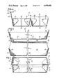
- FIG. 5 is an enlarged sectional view, with parts broken away and shown in section, drawn on substantially the same scale as FIG. 4, and taken substantially on line 5--5 of FIG. 2.
- FIG. 6 is an enlarged sectional view, with parts broken away and shown in section, drawn on substantially the same scale as FIGS. 4 and 5, and taken substantially on line 6--6 of FIG. 2.
- FIG. 7 is a sectional view, with parts broken away and shown in section, drawn on substantially the same scale of FIGS. 4, 5, 6, and taken substantially on line 7--7 of FIG. 3.
- FIG. 8 is a perspective view drawn on substantially the same scale as FIGS. 1-3, and illustrating a plurality of containers of this invention in an open condition and stacked or nested.
- FIG. 9 is a perspective view illustrating a two-piece container of this invention. This view is drawn substantially on the same scale as FIGS. 1-3.
- FIG. 10 is a perspective view drawn on substantially the same scale as FIG. 9, illustrating the two pieces of the container of FIG. 9, separated and in position for attachment together for closing the container.
- FIG. 11 is a perspective view, drawn on substantially the same scale as FIGS. 9 and 10, and showing the container in closed condition.
- FIG. 12 is an enlarged sectional view, with parts broken away and shown in section, and taken substantially on line 12--12 of FIG. 10.
- FIG. 13 is an enlarged sectional view, with parts broken away, and shown in section, and drawn on substantially the same scale as FIG. 12, and taken substantially on line 13--13 of FIG. 11.
- FIG. 14 is a perspective view drawn on substantially the same scale as FIGS. 9-11, and illustrating a plurality of the containers in stacked or nested condition, with the two pieces of the container separated.
- FIGS. 1-8 show a one-piece container or carton 20 of this invention.
- FIG. 1 shows a sheet of material or blank 18 with portions formed for folding and for mutual attachment to form the one piece container or carton 20.
- the blank or sheet 18 comprises an upper panel 24 and a lower panel 26.
- Joining the upper panel 24 to the lower panel 26 are a connector wall 28 and a connector wall 30.
- the connector wall 28 is separated from the upper panel 24 by a crease line 32.
- the connector wall 28 is separated from the wall 30 by a hinge line 34.
- the connector wall 30 is separated from the lower panel 26 by a crease line 36.
- a wall 42 Joined to the lower panel 26 by means of a crease line 40 is a wall 42.
- the wall 42 has a U-shape slit 44 from which a pair of opposed crease lines 46 extend.
- the U-shape slit 44 and the crease lines 46 form a latch 50, which is an integral part of a flap 52.
- the U-shape slit 44 and the crease lines 46 separate the flap 52 from the wall 42.
- tabs 54 and 55 Extending laterally from opposite parts of the wall 42 are tabs 54 and 55, which are separated from the wall 42 by crease lines 56 and 57, respectively.
- Extending from the lower panel 26 are a wall 58 and a wall 59, which are separated from the lower panel 26 by crease lines 60 and 61, respectively.
- tabs 62 and 64 which are separated from the wall 30 by crease lines 63 and 65.
- tabs 66 and 68 which are separated from the wall 28 by crease lines 67 and 69.
- a slot 74 At the edge of the upper panel 24, and between the upper panel 24 and a wall 78, is a slot 74. At opposed ends of the slot 74 are crease lines 76. The slot 74 and the crease lines 76 separate the upper panel 24 from the wall 78. At opposed ends of the wall 78 are tabs 80 and 82, which are separated from the wall 78 by crease lines 81 and 83, respectively.
- the blank 18 is preferably of corrugated paper or paper-like material or the like.
- the blank 18 is of a material referred to as "E-flute" corrugated material, which has a thickness of about one-sixteenth of an inch.
- the corrugations or flutes are best shown in FIGS. 1-7 as extending longitudinally through the blank 18, through the flap 52 and from the flap 52, to the wall 78, and through the wall 78. Therefore, in this arrangement of the flutes or corrugations, each crease can be accurately positioned in the location desired in the blank 18. Furthermore, in this arrangement of the flutes or corrugations most of the creases are normal to the flutes or corrugations. Creases in the blank 18 which are normal to the flutes or corrugations are stronger creases than creases which are parallel to the flutes or corrugations.
- parts of the blank 18 are folded and attached together. As illustrated in FIG. 2, the wall 78 is folded along the crease lines 76, and the walls 70 and 72 are folded along the crease lines 71 and 73, respectively.
- the tabs 80 and 82 are attached to the walls 70 and 72, respectively.
- the connector walls 28 and 30 are folded along the hinge line 34. Thus, the connector walls 28 and 30 are angularly positioned, one with respect to the other. The connector walls 28 and 30 are also folded along the crease lines 32 and 36, respectively. Thus, the connector walls 28 and 30 are angularly positioned with respect to the upper panel 24 and the lower panel 26.
- the tab 68 is attached to the wall 72.
- the tab 66 is attached to the wall 70.
- the wall 59 is folded along the crease line 61.
- the wall 58 is folded along the crease line 60.
- the tab 64 is attached to the wall 59.
- the tab 62 is attached to the wall 58.
- the wall 42 is folded along the crease line 40.
- the tab 55 is attached to the wall 59.
- the tab 54 is attached to the wall 58.
- the flap 52 is folded along the crease lines 46, so that the latch 50 extends angularly from the wall 42, as illustrated in FIGS. 2 and 4.
- the attachments of the tabs to the walls as described above are preferably made by suitable adhesive means.
- the lower panel 26 and the parts attached thereto form a body portion of the container 20, and the upper panel 24 and the parts attached thereto form a cover portion of the container 20.
- the upper panel 24 and the parts attached thereto are pivotally moved about the hinge line 34.
- the wall 78 partially covers the wall 42.
- the flap 52 pivotally moves about the crease lines 46.
- the latch 50 automatically moves into the slot 74, and the container 20 is automatically latched in a closed condition when the container 20 is closed, as shown in FIG. 7.
- the upper panel 24 is substantially parallel to the lower panel 26. In this position the latch 50 is within the slot 74 and the flap 52 engages the upper panel 24 as best shown in FIG. 7.
- the latch 50 is firmly retained by the upper panel 24 within the slot 74 and the container 20 is firmly retained in a closed position.
- latching of the upper panel 24 to the lower panel 26 is automatic as the upper panel 24 is brought into parallel relationship with the lower panel 26.
- the wall 42 When it is desired to open the container 20, the wall 42 is forced inwardly. Thus the latch 50 is removed from the slot 74, and the upper panel 24 can be pivotally moved away from the lower panel 26.
- a container 20 of this invention is preferably constructed of thin corrugated paper-like material, and has excellent thermal insulation qualities.
- a container 20 of this invention is constructed of E-flute corrugated material, the container 20 is extremely light in weight, in consideration of its physical dimensions, while also being strong, sturdy, and durable.
- each of the tabs 82, 68, 64, 55, 54, 62, 66, and 80 is separated from its respective wall by a crease line which is angular with respect to the wall to which the tab is attached.
- the walls 72, 78, 70 are slightly angular with respect to the upper panel 24, and the walls 59, 42, and 58 are slightly angular with respect to the lower panel 26.
- the wall 30 is slightly angular with respect to the lower panel 26, and the wall 28 is slightly angular with respect to the upper panel 24.
- the angular relationship between the walls and the panels is preferably in the order of 98 to 108 degrees. As shown in FIGS. 3 and 7, as a result of this angular relationship, when the container 20 is closed, the walls 78, 70, and 72 substantially cover the walls 42, 58 and 59 which are attached to the lower panel 26. Thus, there is good coverage of walls 78, 70, and 72 over the walls 42, 58, and 59 to effectively close the container 20. Also, as a result of the angular relationship, a plurality of containers 20 is easily and readily stacked, as illustrated in FIG. 8, and when stacked, the containers 20 create a minimum height condition.
- FIGS. 9-14 pertain to a container 120 of this invention which is constructed in two pieces, an upper piece 124 and a lower piece 126.
- the lower piece 126 includes a lower panel 128 and side walls 130 and 132.
- the side walls 130 and 132 are substantially identical.
- the lower piece 126 also includes end walls 136 and 138.
- the end walls 136 and 138 are substantially identical.
- the lower piece 126 is constructed from a blank in a manner similar to the construction of the container 20.
- the side walls 130 and 132 and the end walls 136 and 138 are folded with respect to the lower panel 128.
- the side walls 130 and 132 are attached to the end walls 136 and 138 by means of tabs 139, which extend from the end walls 136 and 138.
- Extending upwardly from the end wall 136 is a flap 140, which is separated from the end wall 136 by a pair of spaced-apart crease lines 142.
- the crease lines 142 are separated by a latch 146, which is cut from the end wall 136.
- the flap 140 and the latch 146 are similar to the flap 52 and the latch 50 of the container 20 of FIGS. 1-8.
- a flap 150 Extending upwardly from the end wall 138 is a flap 150, which is separated from the end wall 138 by a pair of spaced-apart crease lines 152.
- the crease lines 152 are separated by a latch 156 which is cut from the end wall 138.
- the flap 150 and the latch 156 are similar to the flap 140 and the latch 146 of the end wall 136.
- the upper piece 124 is also constructed in a manner somewhat similar to that of the container 20.
- the upper piece 124 includes an upper panel 158.
- the upper piece 124 includes side walls 160 and 162, which are folded with respect to the upper panel 158.
- the upper piece 124 also includes end walls 166 and 168, which are folded with respect to the upper panel 158.
- the side walls 160 and 162 are attached to the end walls 166 and 168 by tabs 170, which extend from the end walls 166 and 168.
- the end walls 166 and 168 are separated from the upper panel 158 by spaced-apart crease lines 176.
- the crease lines 176 are separated by a slot 180.
- the upper piece 124 When it is desired to close the two-piece container, the upper piece 124 is inverted from the position thereof shown in FIG. 9 and moved to the position shown in FIGS. 10 and 12, above the lower piece 126. Then the upper piece 124 is lowered into engagement with the lower piece 126, as illustrated in FIGS. 11 and 13. As the upper piece 124 is lowered toward the lower piece 126, the side walls 160 and 162 of the upper piece 124 engage the side walls 130 and 132 of the lower piece 126. The end walls 168 and 166 engage the end walls 138 and 136 of the lower piece 126.
- the latch 146 moves into the slot 180 of the upper piece 124, and the latch 156 moves into the slot 180 of the upper piece 124.
- the flaps 140 and 150 which are integral with the latches 146 and 156 engage the upper panel 158, as shown in FIG. 13.
- the latches 146 and 156 are maintained within the slots 180.
- the upper piece 124 is firmly attached to the lower piece 126.
- the upper piece 124 comprises a cover member of the container 120 and the lower piece 126 comprises a body member of the container 120.
- the end walls 166 and 168 are bent outwardly from the end walls 136 and 138 of the lower piece 126.
- the latches 146 and 156 are released from the slots 180 and the upper piece 124 can be removed from the lower piece 126.
- a plurality of the upper pieces 124 can be stacked or nested, and a plurality of the lower pieces 126 can be stacked or nested.
- This condition is possible in the upper piece 124 as a result of the angular relationship between the upper panel 158 and the walls 160, 162, 166, and 168.
- This condition is possible in the lower piece 126 as a result of the angular relationship between the lower panel 128 and the walls 130, 132, 136, and 138.
- This angular relationship in the upper piece 124 and the lower piece 126 is preferably in the order of about 98 to 108 degrees.
- the two-piece container 120 of this invention is also preferably constructed of corrugated paper or paper-like material.
- the corrugations are of the E-flute type.
- the flutes or corrugations extend from the flap 140 to the flap 150 in the lower piece 126, and from the wall 166 to the wall 168 in the upper piece 124. Therefore, the two-piece container 120 has all of the characteristics and advantages of the one-piece container 20.
Abstract
Description
Claims (7)
Priority Applications (1)
| Application Number | Priority Date | Filing Date | Title |
|---|---|---|---|
| US07/233,224 US4930681A (en) | 1988-08-18 | 1988-08-18 | Automatic latching container having good thermal insulation |
Applications Claiming Priority (1)
| Application Number | Priority Date | Filing Date | Title |
|---|---|---|---|
| US07/233,224 US4930681A (en) | 1988-08-18 | 1988-08-18 | Automatic latching container having good thermal insulation |
Publications (1)
| Publication Number | Publication Date |
|---|---|
| US4930681A true US4930681A (en) | 1990-06-05 |
Family
ID=22876400
Family Applications (1)
| Application Number | Title | Priority Date | Filing Date |
|---|---|---|---|
| US07/233,224 Expired - Fee Related US4930681A (en) | 1988-08-18 | 1988-08-18 | Automatic latching container having good thermal insulation |
Country Status (1)
| Country | Link |
|---|---|
| US (1) | US4930681A (en) |
Cited By (47)
| Publication number | Priority date | Publication date | Assignee | Title |
|---|---|---|---|---|
| US4985932A (en) * | 1990-04-30 | 1991-01-22 | Bezdek William J | Food spill catching and serving device |
| US5037026A (en) * | 1990-12-10 | 1991-08-06 | Gulf States Paper Corporation | Closable carton with improved snap action lock |
| US5044549A (en) * | 1990-06-15 | 1991-09-03 | International Paper Company | Clamshell type carton |
| US5058803A (en) * | 1990-12-27 | 1991-10-22 | Gulf States Paper Corporation | Carton with over center toggle action indicating tab |
| DE9115841U1 (en) * | 1991-12-20 | 1992-02-20 | Koch, Herbert, 5600 Wuppertal, De | |
| US5188284A (en) * | 1992-02-10 | 1993-02-23 | Dopaco, Inc. | Carton with lug locked tray and cover |
| WO1993004936A1 (en) * | 1991-09-09 | 1993-03-18 | Ecolab Inc. | Dispenser for moisture-sensitive packages |
| US5226587A (en) * | 1992-02-10 | 1993-07-13 | Dopaco, Inc. | Food carton |
| US5427308A (en) * | 1994-08-10 | 1995-06-27 | Eco-Cool, Inc. | Container with integral handles and locking tabs |
| WO1996020832A1 (en) * | 1995-01-05 | 1996-07-11 | A*Ware Technologies, L.C. | Coated sheet material and method |
| US5553772A (en) * | 1995-10-31 | 1996-09-10 | International Paper | Paperboard clamshell carton |
| US5577989A (en) * | 1994-06-20 | 1996-11-26 | Newark Group Industries, Inc. | Method for forming corrugated paper container and container made therefrom |
| US5603996A (en) * | 1992-01-22 | 1997-02-18 | A*Ware Technologies, L.C. | Coated sheet material and method |
| US5603450A (en) * | 1995-11-08 | 1997-02-18 | Dopaco, Inc. | Covered carton |
| US5662508A (en) * | 1995-11-13 | 1997-09-02 | Inland Container Corporation | Toy building blocks |
| US5707004A (en) * | 1997-01-07 | 1998-01-13 | Dopaco, Inc. | Carton with offset lock |
| US5718368A (en) * | 1996-01-25 | 1998-02-17 | Boise Cascade Corporation | Food container |
| US5908152A (en) * | 1997-09-18 | 1999-06-01 | Burrows Paper Corporation | Multi-compartment box including a lid |
| US5921466A (en) * | 1998-11-13 | 1999-07-13 | Arvco Container Corporation | Stackable, foldable food container |
| US6065669A (en) * | 1996-10-16 | 2000-05-23 | Correll; John D. | Slanting-wall pizza box |
| US6092719A (en) * | 1998-02-19 | 2000-07-25 | Graphic Packaging Corporation | Container formed of identical container elements and blank for forming the same |
| US6161331A (en) * | 1999-04-30 | 2000-12-19 | Lalane; Renee | Bulb casing for proper positioning, feeding and protection of plant bulbs |
| US6223979B1 (en) | 1999-12-01 | 2001-05-01 | John D. Correll | Crush-resisting paperboard clamshell carton |
| US6505769B2 (en) | 2001-04-19 | 2003-01-14 | Caraustar Custom Packaging | Partial web in tray corners |
| US6676010B1 (en) | 2002-09-18 | 2004-01-13 | Mastercraft Packaging Corporation | Reclosable food container |
| US6684591B2 (en) * | 2000-11-28 | 2004-02-03 | Richard Jean | Card like construction element |
| US20040182916A1 (en) * | 2003-03-19 | 2004-09-23 | Roseth Steven H. | Reclosable food container |
| US20040195144A1 (en) * | 2003-04-01 | 2004-10-07 | Smith Dwight J. | Food and beverage tray |
| US20050204705A1 (en) * | 2002-05-09 | 2005-09-22 | Burch William B Jr | Structure and process for packaging and shipping produce |
| US20060293158A1 (en) * | 2005-06-23 | 2006-12-28 | Isamu Sato | Method of manufacturing a food container |
| DE202005014738U1 (en) * | 2005-09-19 | 2007-02-08 | Seda S.P.A., Arzano | Container and cut |
| US20070130873A1 (en) * | 2003-08-01 | 2007-06-14 | Hugh Fisher | Building elements |
| US20070221717A1 (en) * | 2006-03-27 | 2007-09-27 | Bradley John Burke | Blank and methods of constructing a food holder from the blank |
| US20070227527A1 (en) * | 2006-04-01 | 2007-10-04 | Kopp John G | Break-apart assembly for supporting an exhaust flue and providing a cumbustible materials top and a fire stop |
| EP1942060A1 (en) * | 2007-01-08 | 2008-07-09 | hvb Innova AG | Packaging conainer and method for its production |
| US20100237139A1 (en) * | 2009-03-23 | 2010-09-23 | Bull Nicholas R | Apparatus Pertaining to a Single-Piece Blank and a Corresponding Clamshell-Style Carton |
| WO2012048898A1 (en) * | 2010-10-15 | 2012-04-19 | Seda S.P.A. | Carton and blank thereof |
| US8733622B2 (en) | 2011-10-07 | 2014-05-27 | Dopaco, Inc. | Blank and container having an anti-buckling mechanism |
| US20140332542A1 (en) * | 2013-05-07 | 2014-11-13 | David M. Hanna | Food carrier |
| WO2017003375A1 (en) * | 2015-06-30 | 2017-01-05 | Microwave Packaging (S) Pte. Ltd. | Food receptacle |
| US10053259B2 (en) | 2015-02-27 | 2018-08-21 | Graphic Packaging International, Llc | Construct with locking features |
| US10086972B2 (en) | 2015-06-09 | 2018-10-02 | Graphic Packaging International, Llc | Carton with locking feature |
| GB2522091B (en) * | 2014-01-10 | 2018-10-17 | Loadhog Ltd | Container |
| USD842691S1 (en) * | 2017-10-10 | 2019-03-12 | Lbp Manufacturing Llc | Two-piece food container |
| US10414573B2 (en) | 2013-06-03 | 2019-09-17 | Graphic Packaging International, Llc | Container with window and microwave interactive material |
| USD866316S1 (en) * | 2017-09-08 | 2019-11-12 | Acushnet Company | Shoe storage box |
| WO2022271081A1 (en) * | 2021-06-25 | 2022-12-29 | Boon Wee Lau | A food box |
Citations (23)
| Publication number | Priority date | Publication date | Assignee | Title |
|---|---|---|---|---|
| US2683561A (en) * | 1950-11-10 | 1954-07-13 | Sutherland Paper Co | Container adapted for food products |
| US2711282A (en) * | 1951-12-14 | 1955-06-21 | Container Corp | Container with locking cover |
| US2765973A (en) * | 1950-02-28 | 1956-10-09 | Reuben M Goldstein | Mailing or shipping carton |
| US2839236A (en) * | 1953-10-14 | 1958-06-17 | Waldorf Paper Products Co | Carton closure |
| US3385424A (en) * | 1966-04-11 | 1968-05-28 | Robertshaw Controls Co | Carton and insert |
| US4232816A (en) * | 1979-03-16 | 1980-11-11 | Container Corporation Of America | Clamshell type carton |
| US4240576A (en) * | 1978-05-10 | 1980-12-23 | Duni Bila Ab | Distribution package |
| US4266713A (en) * | 1979-10-26 | 1981-05-12 | American Can Company | Unitary double cavity carton |
| US4289491A (en) * | 1979-06-25 | 1981-09-15 | Kliklok Corporation | Apparatus for adhesively bonding a carton |
| US4470538A (en) * | 1983-07-05 | 1984-09-11 | Container Corporation Of America | Carton with common tray-cover components |
| US4648549A (en) * | 1985-04-16 | 1987-03-10 | Jefferson Smurfit Corporation | Self-locking container |
| US4655366A (en) * | 1985-05-20 | 1987-04-07 | Walnut Industries, Inc. | Reinforced container and method of making |
| US4655386A (en) * | 1981-08-27 | 1987-04-07 | Tetra Pak International Ab | Packing container blank and container made therefrom |
| US4662559A (en) * | 1983-07-29 | 1987-05-05 | Kouhei Uryu | Folding thick paper box for (menstruous) filthy goods and support structure thereof |
| US4676430A (en) * | 1983-12-05 | 1987-06-30 | E. I. Du Pont De Nemours & Co. | End-load top-dispensing container with tuck closure |
| US4676428A (en) * | 1985-06-28 | 1987-06-30 | Inland Container Corporation | Fold line relief cuts for paperboard containers and method of fabrication |
| US4679726A (en) * | 1986-01-17 | 1987-07-14 | The Mead Corporation | End closure structure for an end loading carton |
| US4684058A (en) * | 1986-05-22 | 1987-08-04 | Ralston Purina Company | Carton with pour spout |
| US4688675A (en) * | 1985-02-27 | 1987-08-25 | Buckhorn Material Handling Group, Inc. | Nesting box with reduced lid flares |
| US4688673A (en) * | 1985-01-17 | 1987-08-25 | Yoshiharu Yabe | Foldup paper container |
| US4712728A (en) * | 1987-04-02 | 1987-12-15 | Manville Corporation | Carton with improved handle |
| US4744507A (en) * | 1985-02-20 | 1988-05-17 | Morsbach Guenter | Packaging material blank of cardboard or the like for a multipack package |
| US4763832A (en) * | 1988-01-21 | 1988-08-16 | Westvaco Corporation | Carton with bottom lock |
-
1988
- 1988-08-18 US US07/233,224 patent/US4930681A/en not_active Expired - Fee Related
Patent Citations (23)
| Publication number | Priority date | Publication date | Assignee | Title |
|---|---|---|---|---|
| US2765973A (en) * | 1950-02-28 | 1956-10-09 | Reuben M Goldstein | Mailing or shipping carton |
| US2683561A (en) * | 1950-11-10 | 1954-07-13 | Sutherland Paper Co | Container adapted for food products |
| US2711282A (en) * | 1951-12-14 | 1955-06-21 | Container Corp | Container with locking cover |
| US2839236A (en) * | 1953-10-14 | 1958-06-17 | Waldorf Paper Products Co | Carton closure |
| US3385424A (en) * | 1966-04-11 | 1968-05-28 | Robertshaw Controls Co | Carton and insert |
| US4240576A (en) * | 1978-05-10 | 1980-12-23 | Duni Bila Ab | Distribution package |
| US4232816A (en) * | 1979-03-16 | 1980-11-11 | Container Corporation Of America | Clamshell type carton |
| US4289491A (en) * | 1979-06-25 | 1981-09-15 | Kliklok Corporation | Apparatus for adhesively bonding a carton |
| US4266713A (en) * | 1979-10-26 | 1981-05-12 | American Can Company | Unitary double cavity carton |
| US4655386A (en) * | 1981-08-27 | 1987-04-07 | Tetra Pak International Ab | Packing container blank and container made therefrom |
| US4470538A (en) * | 1983-07-05 | 1984-09-11 | Container Corporation Of America | Carton with common tray-cover components |
| US4662559A (en) * | 1983-07-29 | 1987-05-05 | Kouhei Uryu | Folding thick paper box for (menstruous) filthy goods and support structure thereof |
| US4676430A (en) * | 1983-12-05 | 1987-06-30 | E. I. Du Pont De Nemours & Co. | End-load top-dispensing container with tuck closure |
| US4688673A (en) * | 1985-01-17 | 1987-08-25 | Yoshiharu Yabe | Foldup paper container |
| US4744507A (en) * | 1985-02-20 | 1988-05-17 | Morsbach Guenter | Packaging material blank of cardboard or the like for a multipack package |
| US4688675A (en) * | 1985-02-27 | 1987-08-25 | Buckhorn Material Handling Group, Inc. | Nesting box with reduced lid flares |
| US4648549A (en) * | 1985-04-16 | 1987-03-10 | Jefferson Smurfit Corporation | Self-locking container |
| US4655366A (en) * | 1985-05-20 | 1987-04-07 | Walnut Industries, Inc. | Reinforced container and method of making |
| US4676428A (en) * | 1985-06-28 | 1987-06-30 | Inland Container Corporation | Fold line relief cuts for paperboard containers and method of fabrication |
| US4679726A (en) * | 1986-01-17 | 1987-07-14 | The Mead Corporation | End closure structure for an end loading carton |
| US4684058A (en) * | 1986-05-22 | 1987-08-04 | Ralston Purina Company | Carton with pour spout |
| US4712728A (en) * | 1987-04-02 | 1987-12-15 | Manville Corporation | Carton with improved handle |
| US4763832A (en) * | 1988-01-21 | 1988-08-16 | Westvaco Corporation | Carton with bottom lock |
Non-Patent Citations (1)
| Title |
|---|
| Distribution Packaging by Friedman & Kipnees, published by Robert E. Krieger Publishing Co., 1977, pp. 68 to 69. * |
Cited By (60)
| Publication number | Priority date | Publication date | Assignee | Title |
|---|---|---|---|---|
| US4985932A (en) * | 1990-04-30 | 1991-01-22 | Bezdek William J | Food spill catching and serving device |
| US5044549A (en) * | 1990-06-15 | 1991-09-03 | International Paper Company | Clamshell type carton |
| US5037026A (en) * | 1990-12-10 | 1991-08-06 | Gulf States Paper Corporation | Closable carton with improved snap action lock |
| US5058803A (en) * | 1990-12-27 | 1991-10-22 | Gulf States Paper Corporation | Carton with over center toggle action indicating tab |
| WO1993004936A1 (en) * | 1991-09-09 | 1993-03-18 | Ecolab Inc. | Dispenser for moisture-sensitive packages |
| US5249737A (en) * | 1991-09-09 | 1993-10-05 | Ecolab Inc. | Method for dispensing moisture-sensitive unit dose packages |
| US5328082A (en) * | 1991-09-09 | 1994-07-12 | Ecolab Inc. | Apparatus for dispensing moisture-sensitive unit dose packages |
| DE9115841U1 (en) * | 1991-12-20 | 1992-02-20 | Koch, Herbert, 5600 Wuppertal, De | |
| US5603996A (en) * | 1992-01-22 | 1997-02-18 | A*Ware Technologies, L.C. | Coated sheet material and method |
| US5981011A (en) | 1992-01-22 | 1999-11-09 | A*Ware Technologies, L.C. | Coated sheet material |
| US5188284A (en) * | 1992-02-10 | 1993-02-23 | Dopaco, Inc. | Carton with lug locked tray and cover |
| US5226587A (en) * | 1992-02-10 | 1993-07-13 | Dopaco, Inc. | Food carton |
| US5249736A (en) * | 1992-02-10 | 1993-10-05 | Dopaco, Inc. | Food carton with cover |
| US6193831B1 (en) | 1993-09-20 | 2001-02-27 | A⋆Ware Technologies, L.C. | Coated sheet method |
| US5577989A (en) * | 1994-06-20 | 1996-11-26 | Newark Group Industries, Inc. | Method for forming corrugated paper container and container made therefrom |
| US5628451A (en) * | 1994-06-20 | 1997-05-13 | Newark Group Industries, Inc. | Corrugated paper container |
| US5427308A (en) * | 1994-08-10 | 1995-06-27 | Eco-Cool, Inc. | Container with integral handles and locking tabs |
| WO1996020832A1 (en) * | 1995-01-05 | 1996-07-11 | A*Ware Technologies, L.C. | Coated sheet material and method |
| US5553772A (en) * | 1995-10-31 | 1996-09-10 | International Paper | Paperboard clamshell carton |
| US5603450A (en) * | 1995-11-08 | 1997-02-18 | Dopaco, Inc. | Covered carton |
| US5662508A (en) * | 1995-11-13 | 1997-09-02 | Inland Container Corporation | Toy building blocks |
| US5718368A (en) * | 1996-01-25 | 1998-02-17 | Boise Cascade Corporation | Food container |
| US6065669A (en) * | 1996-10-16 | 2000-05-23 | Correll; John D. | Slanting-wall pizza box |
| US5707004A (en) * | 1997-01-07 | 1998-01-13 | Dopaco, Inc. | Carton with offset lock |
| US5908152A (en) * | 1997-09-18 | 1999-06-01 | Burrows Paper Corporation | Multi-compartment box including a lid |
| US6092719A (en) * | 1998-02-19 | 2000-07-25 | Graphic Packaging Corporation | Container formed of identical container elements and blank for forming the same |
| US5921466A (en) * | 1998-11-13 | 1999-07-13 | Arvco Container Corporation | Stackable, foldable food container |
| US6161331A (en) * | 1999-04-30 | 2000-12-19 | Lalane; Renee | Bulb casing for proper positioning, feeding and protection of plant bulbs |
| US6223979B1 (en) | 1999-12-01 | 2001-05-01 | John D. Correll | Crush-resisting paperboard clamshell carton |
| US6684591B2 (en) * | 2000-11-28 | 2004-02-03 | Richard Jean | Card like construction element |
| US6505769B2 (en) | 2001-04-19 | 2003-01-14 | Caraustar Custom Packaging | Partial web in tray corners |
| US20050204705A1 (en) * | 2002-05-09 | 2005-09-22 | Burch William B Jr | Structure and process for packaging and shipping produce |
| US6676010B1 (en) | 2002-09-18 | 2004-01-13 | Mastercraft Packaging Corporation | Reclosable food container |
| US20040182916A1 (en) * | 2003-03-19 | 2004-09-23 | Roseth Steven H. | Reclosable food container |
| US20040195144A1 (en) * | 2003-04-01 | 2004-10-07 | Smith Dwight J. | Food and beverage tray |
| US20070130873A1 (en) * | 2003-08-01 | 2007-06-14 | Hugh Fisher | Building elements |
| US20110023402A1 (en) * | 2003-08-01 | 2011-02-03 | Hugh Fisher | Building Elements |
| US7507195B2 (en) * | 2005-06-23 | 2009-03-24 | Isamu Sato | Method of manufacturing a food container |
| US20060293158A1 (en) * | 2005-06-23 | 2006-12-28 | Isamu Sato | Method of manufacturing a food container |
| US20080045392A1 (en) * | 2005-06-23 | 2008-02-21 | Shinkichi Hamano | Method of manufacturing a food container |
| DE202005014738U1 (en) * | 2005-09-19 | 2007-02-08 | Seda S.P.A., Arzano | Container and cut |
| US20070221717A1 (en) * | 2006-03-27 | 2007-09-27 | Bradley John Burke | Blank and methods of constructing a food holder from the blank |
| US8820621B2 (en) * | 2006-03-27 | 2014-09-02 | Graphic Packaging International, Inc. | Blank and methods of constructing a food holder from the blank |
| US7490600B2 (en) * | 2006-04-01 | 2009-02-17 | Kopp John G | Break-apart assembly for supporting an exhaust flue and providing a cumbustible materials top and a fire stop |
| US20070227527A1 (en) * | 2006-04-01 | 2007-10-04 | Kopp John G | Break-apart assembly for supporting an exhaust flue and providing a cumbustible materials top and a fire stop |
| EP1942060A1 (en) * | 2007-01-08 | 2008-07-09 | hvb Innova AG | Packaging conainer and method for its production |
| US20100237139A1 (en) * | 2009-03-23 | 2010-09-23 | Bull Nicholas R | Apparatus Pertaining to a Single-Piece Blank and a Corresponding Clamshell-Style Carton |
| US8485421B2 (en) * | 2009-03-23 | 2013-07-16 | Kraft Foods Group Brands Llc | Apparatus pertaining to a single-piece blank and a corresponding clamshell-style carton |
| WO2012048898A1 (en) * | 2010-10-15 | 2012-04-19 | Seda S.P.A. | Carton and blank thereof |
| US8733622B2 (en) | 2011-10-07 | 2014-05-27 | Dopaco, Inc. | Blank and container having an anti-buckling mechanism |
| US20140332542A1 (en) * | 2013-05-07 | 2014-11-13 | David M. Hanna | Food carrier |
| US10414573B2 (en) | 2013-06-03 | 2019-09-17 | Graphic Packaging International, Llc | Container with window and microwave interactive material |
| GB2522091B (en) * | 2014-01-10 | 2018-10-17 | Loadhog Ltd | Container |
| US10227159B2 (en) | 2014-01-10 | 2019-03-12 | Loadhog Limited | Nestable containers having nestable lid arrangements |
| US10053259B2 (en) | 2015-02-27 | 2018-08-21 | Graphic Packaging International, Llc | Construct with locking features |
| US10086972B2 (en) | 2015-06-09 | 2018-10-02 | Graphic Packaging International, Llc | Carton with locking feature |
| WO2017003375A1 (en) * | 2015-06-30 | 2017-01-05 | Microwave Packaging (S) Pte. Ltd. | Food receptacle |
| USD866316S1 (en) * | 2017-09-08 | 2019-11-12 | Acushnet Company | Shoe storage box |
| USD842691S1 (en) * | 2017-10-10 | 2019-03-12 | Lbp Manufacturing Llc | Two-piece food container |
| WO2022271081A1 (en) * | 2021-06-25 | 2022-12-29 | Boon Wee Lau | A food box |
Similar Documents
| Publication | Publication Date | Title |
|---|---|---|
| US4930681A (en) | Automatic latching container having good thermal insulation | |
| US5289970A (en) | Paperboard container having reinforced corners | |
| US8240478B2 (en) | Multi-product container and container blank | |
| US5209392A (en) | Recyclable pizza box | |
| US5211329A (en) | Food product container | |
| US4511079A (en) | Variable dimension container | |
| US7004314B2 (en) | Multi-product container | |
| US7464855B2 (en) | Combo box and associated blank | |
| EP0524720B1 (en) | Blank for a cigarette box and hinge lid cigarette carton erected from said blank | |
| US4307834A (en) | Take out carton and blank for forming same | |
| US6065669A (en) | Slanting-wall pizza box | |
| US4168028A (en) | Shipping box for coats | |
| EP0912406A1 (en) | Improvements in or relating to containers | |
| US4477015A (en) | Two-piece, self-locking container | |
| US4136816A (en) | Self locking container | |
| US4311268A (en) | Footwear box with handles | |
| US5402932A (en) | Receptacle with corner lock | |
| US4003515A (en) | Handle container | |
| US5799864A (en) | Container closure arrangement | |
| US4239148A (en) | Storage box | |
| EP1066199A1 (en) | Trays | |
| US5044549A (en) | Clamshell type carton | |
| US4166568A (en) | Polygonal container | |
| US6386441B2 (en) | Single-piece pizza container with fold and hold mechanism | |
| US4129247A (en) | Die-cut carton with built-in fillers |
Legal Events
| Date | Code | Title | Description |
|---|---|---|---|
| AS | Assignment |
Owner name: PROGRESSIVE PAPER PRODUCTS, INC., A CORPORATION OF Free format text: ASSIGNMENT OF ASSIGNORS INTEREST.;ASSIGNORS:FULTZ, CLINTON;DALTON, STANLEY;REEL/FRAME:005748/0792 Effective date: 19910225 |
|
| FPAY | Fee payment |
Year of fee payment: 4 |
|
| AS | Assignment |
Owner name: TEMPLE-INLAND FOOD SERVICE CORPORATION, INDIANA Free format text: MERGER;ASSIGNOR:PROGRESSIVE PAPER PRODUCTS, INC.;REEL/FRAME:008709/0168 Effective date: 19911226 |
|
| AS | Assignment |
Owner name: DOPACO, INC., PENNSYLVANIA Free format text: ASSIGNMENT OF ASSIGNORS INTEREST;ASSIGNOR:TEMPLE-INLAND FOOD SERVICE CORPORATION;REEL/FRAME:008955/0251 Effective date: 19971027 |
|
| REMI | Maintenance fee reminder mailed | ||
| LAPS | Lapse for failure to pay maintenance fees | ||
| FP | Lapsed due to failure to pay maintenance fee |
Effective date: 19980610 |
|
| STCH | Information on status: patent discontinuation |
Free format text: PATENT EXPIRED DUE TO NONPAYMENT OF MAINTENANCE FEES UNDER 37 CFR 1.362 |