US4931339A - Intumescent seals - Google Patents
Intumescent seals Download PDFInfo
- Publication number
- US4931339A US4931339A US07/317,479 US31747989A US4931339A US 4931339 A US4931339 A US 4931339A US 31747989 A US31747989 A US 31747989A US 4931339 A US4931339 A US 4931339A
- Authority
- US
- United States
- Prior art keywords
- intumescent
- seal according
- produces
- materials
- members
- Prior art date
- Legal status (The legal status is an assumption and is not a legal conclusion. Google has not performed a legal analysis and makes no representation as to the accuracy of the status listed.)
- Expired - Fee Related
Links
Images

Classifications
-
- E—FIXED CONSTRUCTIONS
- E04—BUILDING
- E04B—GENERAL BUILDING CONSTRUCTIONS; WALLS, e.g. PARTITIONS; ROOFS; FLOORS; CEILINGS; INSULATION OR OTHER PROTECTION OF BUILDINGS
- E04B1/00—Constructions in general; Structures which are not restricted either to walls, e.g. partitions, or floors or ceilings or roofs
- E04B1/62—Insulation or other protection; Elements or use of specified material therefor
- E04B1/92—Protection against other undesired influences or dangers
- E04B1/94—Protection against other undesired influences or dangers against fire
- E04B1/948—Fire-proof sealings or joints
-
- E—FIXED CONSTRUCTIONS
- E06—DOORS, WINDOWS, SHUTTERS, OR ROLLER BLINDS IN GENERAL; LADDERS
- E06B—FIXED OR MOVABLE CLOSURES FOR OPENINGS IN BUILDINGS, VEHICLES, FENCES OR LIKE ENCLOSURES IN GENERAL, e.g. DOORS, WINDOWS, BLINDS, GATES
- E06B5/00—Doors, windows, or like closures for special purposes; Border constructions therefor
- E06B5/10—Doors, windows, or like closures for special purposes; Border constructions therefor for protection against air-raid or other war-like action; for other protective purposes
- E06B5/16—Fireproof doors or similar closures; Adaptations of fixed constructions therefor
- E06B5/164—Sealing arrangements between the door or window and its frame, e.g. intumescent seals specially adapted therefor
-
- Y—GENERAL TAGGING OF NEW TECHNOLOGICAL DEVELOPMENTS; GENERAL TAGGING OF CROSS-SECTIONAL TECHNOLOGIES SPANNING OVER SEVERAL SECTIONS OF THE IPC; TECHNICAL SUBJECTS COVERED BY FORMER USPC CROSS-REFERENCE ART COLLECTIONS [XRACs] AND DIGESTS
- Y10—TECHNICAL SUBJECTS COVERED BY FORMER USPC
- Y10S—TECHNICAL SUBJECTS COVERED BY FORMER USPC CROSS-REFERENCE ART COLLECTIONS [XRACs] AND DIGESTS
- Y10S428/00—Stock material or miscellaneous articles
- Y10S428/92—Fire or heat protection feature
- Y10S428/921—Fire or flameproofing
-
- Y—GENERAL TAGGING OF NEW TECHNOLOGICAL DEVELOPMENTS; GENERAL TAGGING OF CROSS-SECTIONAL TECHNOLOGIES SPANNING OVER SEVERAL SECTIONS OF THE IPC; TECHNICAL SUBJECTS COVERED BY FORMER USPC CROSS-REFERENCE ART COLLECTIONS [XRACs] AND DIGESTS
- Y10—TECHNICAL SUBJECTS COVERED BY FORMER USPC
- Y10T—TECHNICAL SUBJECTS COVERED BY FORMER US CLASSIFICATION
- Y10T428/00—Stock material or miscellaneous articles
- Y10T428/23—Sheet including cover or casing
- Y10T428/233—Foamed or expanded material encased
-
- Y—GENERAL TAGGING OF NEW TECHNOLOGICAL DEVELOPMENTS; GENERAL TAGGING OF CROSS-SECTIONAL TECHNOLOGIES SPANNING OVER SEVERAL SECTIONS OF THE IPC; TECHNICAL SUBJECTS COVERED BY FORMER USPC CROSS-REFERENCE ART COLLECTIONS [XRACs] AND DIGESTS
- Y10—TECHNICAL SUBJECTS COVERED BY FORMER USPC
- Y10T—TECHNICAL SUBJECTS COVERED BY FORMER US CLASSIFICATION
- Y10T428/00—Stock material or miscellaneous articles
- Y10T428/23—Sheet including cover or casing
- Y10T428/234—Sheet including cover or casing including elements cooperating to form cells
-
- Y—GENERAL TAGGING OF NEW TECHNOLOGICAL DEVELOPMENTS; GENERAL TAGGING OF CROSS-SECTIONAL TECHNOLOGIES SPANNING OVER SEVERAL SECTIONS OF THE IPC; TECHNICAL SUBJECTS COVERED BY FORMER USPC CROSS-REFERENCE ART COLLECTIONS [XRACs] AND DIGESTS
- Y10—TECHNICAL SUBJECTS COVERED BY FORMER USPC
- Y10T—TECHNICAL SUBJECTS COVERED BY FORMER US CLASSIFICATION
- Y10T428/00—Stock material or miscellaneous articles
- Y10T428/24—Structurally defined web or sheet [e.g., overall dimension, etc.]
- Y10T428/2419—Fold at edge
- Y10T428/24198—Channel-shaped edge component [e.g., binding, etc.]
-
- Y—GENERAL TAGGING OF NEW TECHNOLOGICAL DEVELOPMENTS; GENERAL TAGGING OF CROSS-SECTIONAL TECHNOLOGIES SPANNING OVER SEVERAL SECTIONS OF THE IPC; TECHNICAL SUBJECTS COVERED BY FORMER USPC CROSS-REFERENCE ART COLLECTIONS [XRACs] AND DIGESTS
- Y10—TECHNICAL SUBJECTS COVERED BY FORMER USPC
- Y10T—TECHNICAL SUBJECTS COVERED BY FORMER US CLASSIFICATION
- Y10T428/00—Stock material or miscellaneous articles
- Y10T428/24—Structurally defined web or sheet [e.g., overall dimension, etc.]
- Y10T428/24744—Longitudinal or transverse tubular cavity or cell
-
- Y—GENERAL TAGGING OF NEW TECHNOLOGICAL DEVELOPMENTS; GENERAL TAGGING OF CROSS-SECTIONAL TECHNOLOGIES SPANNING OVER SEVERAL SECTIONS OF THE IPC; TECHNICAL SUBJECTS COVERED BY FORMER USPC CROSS-REFERENCE ART COLLECTIONS [XRACs] AND DIGESTS
- Y10—TECHNICAL SUBJECTS COVERED BY FORMER USPC
- Y10T—TECHNICAL SUBJECTS COVERED BY FORMER US CLASSIFICATION
- Y10T428/00—Stock material or miscellaneous articles
- Y10T428/249921—Web or sheet containing structurally defined element or component
- Y10T428/249953—Composite having voids in a component [e.g., porous, cellular, etc.]
- Y10T428/249954—With chemically effective material or specified gas other than air, N, or carbon dioxide in void-containing component
-
- Y—GENERAL TAGGING OF NEW TECHNOLOGICAL DEVELOPMENTS; GENERAL TAGGING OF CROSS-SECTIONAL TECHNOLOGIES SPANNING OVER SEVERAL SECTIONS OF THE IPC; TECHNICAL SUBJECTS COVERED BY FORMER USPC CROSS-REFERENCE ART COLLECTIONS [XRACs] AND DIGESTS
- Y10—TECHNICAL SUBJECTS COVERED BY FORMER USPC
- Y10T—TECHNICAL SUBJECTS COVERED BY FORMER US CLASSIFICATION
- Y10T428/00—Stock material or miscellaneous articles
- Y10T428/249921—Web or sheet containing structurally defined element or component
- Y10T428/249953—Composite having voids in a component [e.g., porous, cellular, etc.]
- Y10T428/249987—With nonvoid component of specified composition
- Y10T428/24999—Inorganic
-
- Y—GENERAL TAGGING OF NEW TECHNOLOGICAL DEVELOPMENTS; GENERAL TAGGING OF CROSS-SECTIONAL TECHNOLOGIES SPANNING OVER SEVERAL SECTIONS OF THE IPC; TECHNICAL SUBJECTS COVERED BY FORMER USPC CROSS-REFERENCE ART COLLECTIONS [XRACs] AND DIGESTS
- Y10—TECHNICAL SUBJECTS COVERED BY FORMER USPC
- Y10T—TECHNICAL SUBJECTS COVERED BY FORMER US CLASSIFICATION
- Y10T428/00—Stock material or miscellaneous articles
- Y10T428/29—Coated or structually defined flake, particle, cell, strand, strand portion, rod, filament, macroscopic fiber or mass thereof
- Y10T428/2902—Channel shape
Definitions
- the present invention relates to intumescent seals.
- the intumescent seals comprise intumescent material which on being subjected to elevated temperature intumesces (i.e. undergoes substantial expansion) to produce a foam of fire-resistant intumesced material, often referred to as "puff".
- intumescent seals comprise intumescent material which produces either a hard foam or a soft foam.
- a hard foam we mean a foam which, although not necessarily rigid, has a relatively high expansion force i.e. will not deform unless substantial pressure is applied to it.
- a hard foam acts as a pressure seal.
- Palusol is an example of an intumescent material based on sodium silicate and which produces on heating, a hard foam. It has been claimed that Palusol is fully intumesced within three minutes of activation.
- a soft foam we mean a foam which has a relatively low expansion force.
- a soft foam acts as a gap-filling foam.
- Intumescent materials which produce soft foams on heating are supplied by Sealmaster Limited and are described in British Pat. No. 1,601,131.
- the soft foam tends to be produced copiously by the intumescent material.
- Intumescent materials which produce hard foams and soft foams in general intumesce at similar temperatures on heating.
- the hard foam may exert considerable pressure between the door and the frame, helping to control warping of the door in the early stage of a fire.
- this type of foam at least when produced from known sodium-silicate based intumescent materials, becomes less and less rigid in performance as the fire progresses and finally becomes relatively soft in practice. A consequence of this is that any further dramatic warping or possibly even minor warping cannot be accommodated.
- the soft foam is (as compared with a hard foam) less able to accommodate severe early warping although the copious foam produced will readily follow the warped surfaces for a prolonged period e.g. 60-70 minutes.
- hard foams may be advantageous in certain situations. E.g. they may be useful to restrain doors from warping under fire conditions. Soft foams may be advantageous in certain other situations. E.g. they may be useful for providing sealing between parts which will inevitably undergo relative movement under fire conditions and may fill irregular gaps better than hard foams.
- Hard foams may also be disadvantageous under certain circumstances, e.g. since these are less voluminous than soft foam, and thus may not be sufficiently gap filling where there is warping or where large air gaps are present.
- Soft foam equally may be disadvantageous under certain circumstances, e.g. they are insufficiently firm to prevent door warping.
- intumescent materials are subject to atmospheric degradation or exposure to air and in particular on exposure to atmospheric moisture.
- the invention aims to provide intumescent seals which combine the advantages of seals which produce hard foam, and of seals which produce soft foam but do not suffer from the disadvantages of either type of seal.
- the invention is based on the concept of providing an intumescent seal comprising separate bodies or masses of intumescent material which produces a hard foam on heating and intumescent material which produces a soft foam on heating, the seal being for disposition at or adjacent a gap to be sealed by the foams produced by the intumescent materials under fire conditions.
- the intumescent material may be accommodated in at least one holder or may be mounted (without any holder) on or in members or parts which, at least in a predetermined relative position, define the gap.
- Such members or parts may be a door or window and an associated fixed frame, the leaves of a pair of double doors or partitions.
- an intumescent seal comprising at least one holder accommodating intumescent material which produces hard foam and intumescent material which produces soft foam.
- the holder or each holder may be of aluminium or polyvinylchloride (PVC).
- the intumescent seal comprises a holder provided with two grooves, channels, recesses or cavities, one accommodating intumescent material which produces a hard foam and the other accommodating the intumescent material which produces a soft foam.
- a draught and smoke sealing blade or other resilient sealing element may be provided between the grooves, channels, recesses or cavities.
- the resilient sealing element may be secured in the holder or may be provided independently of the holder.
- the intumescent seal comprises two holders each having a groove, channel, recess or cavity, the groove, channel, recess or cavity of one holder accommodating intumescent material which produces a hard foam and the groove, channel, recess or cavity of the other holder accommodating intumescent material which produces a soft foam.
- the two holders may be secured adjacent to each other on a common member, e.g. a door or door frame or may be secured respectively to two members so as to be at opposite sides of a gap provided between the members and offset from each other at least in a certain condition, e.g. a closed condition, of the members.
- a certain condition e.g. a closed condition
- one holder may be secured on an edge face (stile) of a door, or in a groove in the edge face
- the other holder may be secured on an opposing face of a door frame, or in a groove in that face.
- a draught and smoke sealing blade or other resilient sealing element may be provided between the grooves, channels, recesses or cavities.
- the sealing element may be carried by one of the holders or may be provided independently of the holders.
- the intumescent seal comprises at least one body of intumescent material which produces a hard foam and at least one body of intumescent material which produces a soft foam, the intumescent materials being carried by at least one of a pair of members or parts between which a gap is defined at least in a predetermined relative position of the two members or parts, the intumescent material being disposed so as to intumesce into the gap on heating at least when the members or parts are in said predetermined position.
- the intumescent materials may be carried by the same member or the intumescent material which produces a hard foam may be carried by one member, the intumescent material which produces soft foam being carried by the other member.
- One of the members may carry a resilient sealing element such as a smoke and draught sealing blade.
- the two intumecent materials may be accommodated in holders as referred to above in connection with the first and second aspects of the invention or may be accommodated in grooves, channels, recesses or cavities cut in at least one of the members.
- the intumescent material may be in the form of strips located in such grooves or channels or may be in the form of plugs located in bores in the members.
- each intumescent material does not intumesce at a temperature below 95° C. but at least begins to intumesce visibly when heated to 160° C.
- the intumescent material which produces the soft foam and, also optionally, the intumescent material which produces the hard foam increase in volume by at least four times, more preferably by at least eight times when they intumesce.
- the intumescent material which produces a hard foam may be based on hydrated sodium silicate, unexfoliated vermiculite or expandible graphite.
- the intumescent material which produces a soft foam may be based on melamine-formaldeyde resin cross-linked by dicyandiamide or guanidine, ammonium phosphate (e.g. monoammonium phosphate or ammonium polyphosphate) and a polyhydroxy compound.
- ammonium phosphate e.g. monoammonium phosphate or ammonium polyphosphate
- a polyhydroxy compound e.g. monoammonium phosphate or ammonium polyphosphate
- FIG. 1 is a sectional view of a first intumescent seal according to the invention
- FIG. 2 is a sectional view of a second intumescent seal according to the invention.
- FIG. 3 is a sectional view of part of a door and an associated frame provided with the seal of FIG. 1;
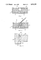
- FIG. 4 is a sectional view of the component parts of a third seal according to the invention.
- FIG. 5 is a sectional view of a door and its associated door frame provided with the seal of FIG. 4;
- FIG. 6 is a diagrammatic side view of apparatus for measuring expansion force.
- FIGS. 1 to 5 of the drawings like reference numerals indicate like parts or features.
- an intumescent seal 1 comprises an elongate aluminium holder 2 of uniform cross-section.
- the holder 2 has two grooves or channels, one filled with intumescent material 3 which on heating produces a hard foam and the other filled with intumescent material 4 which on heating produces a soft foam.
- the grooves or channels have respective openings 5 and 6 through which the intumescent materials intumesce on heating and which are spaced apart.
- the holder has a third, empty groove or channel 8 between the grooves or channels containing the intumescent materials.
- an intumescent seal similar to that shown in FIG. 1 additionally comprises a resilient member providing a smoke and draught sealing blade 13, a base portion of the resilient member being retained in the third groove or channel of the holder.
- a seal 1 as shown in FIG. 1 may be secured in a groove cut into the stile of a door 20.
- the door 20 may be conventionally mounted on hinges and in a door frame 22 so that when the door is closed it abuts against an integral stop 23 of the door frame.
- a gap 24 is defined between the stile of the door and the door frame when the door is closed.
- the gap 24 is sealed by intumescing of the materials 3 and 4 of the seal.
- the seal shown in FIG. 2 may be similarly mounted on the stile of a door. In this case when the door is closed, the blade 13 sealingly engages the door frame 22.
- a seal comprises two holders 31 and 32 respectively each having a groove or channel.
- the groove or channel of the holder 32 is filled with intumescent material 3 which on heating produces a hard foam.
- the groove or channel of the holder 32 is filled with intumescent material 4 which on heating produces a soft foam.
- the grooves or channels have respective openings 34 and 35 through which the intumescent materials intumesce on heating.
- the opening 34 is larger than the opening 35 to encourage upwards expansion, through the opening 34, of the hard foam.
- the holders of a seal as shown in FIG. 4 may be secured respectively to a door 20 and its associated door frame 22.
- the holder 31 is secured in a groove and in the surface of the door frame 22 which faces the stile 21 and the door when the door is closed and the holder 32 is secured in a groove cut in the stile of the door.
- the openings 34 and 35 face into the gap 24 between the stile of the door and the door frame.
- the holders 31 and 32 are offset from each other and consequently the hard and soft foams formed on heating do not contact each other at least until heating has been continued for a prolonged period.
- both holders 31 and 32 may be secured to the door or both holders may be secured to the door frame.
- smoke and draught sealing blades may be provided mounted on the door of the door frame and disposed between the holders, at least when the door is closed.
- One of the holders may be provided with a groove (such as shown in FIG. 2) or other means to retain a member providing the smoke and draught sealing blade.
- the holders need not have openings for the intumescent materials to intumesce through but may be made of materials such as plastics which melt or soften at elevated temperature thereby allowing the intumescent materials to intumesce substantially unconstrained by the holder.
- the intumescent materials may be suitably formulated and provided in the form of strips, which may have a water resistant coating, such strips may be secured in grooves cut in the door and/or door frame.
- intumescent seals described above may be mounted on the meeting stiles of the leaves of double doors in a similar manner to that described with reference to a door and its door frame.
- a seal according to the invention may be provided at the gap and mounted on one or both of the members.
- the holders of the seal may be provided with baffles to hinder tampering as described in our British Pat. No. 1,529,733.
- apparatus for measuring expansion force comprises lkN load cell 1 supported in a sheet steel bridge 2 mounted over an electrically heated platen 3.
- the platen is provided with a pocket 6 for accommodating a specimen or sample comprising intumescent material, the expansion force of which is to be measured.
- a sliding coupling 4 between a pressure plate 5 above the platen 3 and the load cell allows easy removal of the pressure plate and removal of a specimen or sample from the pocket 6.
- the platen 3 accommodates tubular electrical heaters 7.
- the pocket 6 has a length of 8 cm, a width of 2.8 cm and a depth of 0.8 cm. Thus the volume of the pocket is 17.9 cm 3 .
- Expansion force of intumescent material is measured by heating the platen up to 700° C. with the specimen or sample comprising the intumescent material in the pocket 6 and with the pressure plate positioned on the platen.
- the specimen or sample comprises a hollow prism (e.g. of PVC or aluminium) accommodating the intumescent material and having one or more longitudinal slots through which the material can expand when it intumesces.
- the holder has a length of 7.5 cm and contains the intumescent material along its entire length.
- the body of intumescent material in the holder has an average width of about 8 mm, a thickness of about 6.5 mm, and a cross-section of approximately 0.5 cm 2 .
- a gap of 1 mm is provided between the top of the sample and the pressure plate when the pressure plate is positioned on the platen.
- the force exerted on the pressure plate 5 by the intumescent material is measured by the load cell 11.
- the expansion force of the intumescent material is expressed as the force (exerted on the pressure plate 5) per unit length of the specimen or sample including the intumescent material.
- the expansion forces of the intumescent materials providing the hard and soft foams are preferably as follows:
- the expansion force of the hard foam is preferably at least 1.5 times, more preferably at least 3 times, and most preferably at least 5 times the expansion force of the soft foam.
- the intumescent material used in the present invention and which produces the hard foam may comprise expandible graphite and may be as disclosed in our co-pending British patent applications Nos. 8622341, 8622823 and 8623157.
- Such intumescent material is multi-directional in action, e.g., when heated to a temperature sufficient to cause it to intumesce it expands in all directions in which it is free to do so.
- intumescent materials comprising expandible graphite and as disclosed in our co-pending applications are resistant to degradation on exposure to the air and in particular on exposure to the atmospheric moisture.
Abstract
Description
______________________________________
HARD FOAM:  Expansion force    ≧1500 Nm.sup.-1
             More preferably,
                               ≧2000 Nm.sup.-1
            expansion force
E.g. the expansion force may be 2400 to 2500 Nm.sup.-1
SOFT FOAM:  Expansion force
                           ≦1000 Nm.sup.-1
E.g. the expansion force may be 200 to 500 Nm.sup.-1
______________________________________
 (Nm.sup.-1 means Newtons per meter)
Claims (28)
Applications Claiming Priority (4)
| Application Number | Priority Date | Filing Date | Title |
|---|---|---|---|
| GB868620257A GB8620257D0 (en) | 1986-08-20 | 1986-08-20 | Intumescent seals |
| GB8620257 | 1986-08-20 | ||
| GB8624928 | 1986-10-17 | ||
| GB868624928A GB8624928D0 (en) | 1986-08-20 | 1986-10-17 | Intumescent seals |
Publications (1)
| Publication Number | Publication Date |
|---|---|
| US4931339A true US4931339A (en) | 1990-06-05 |
Family
ID=26291199
Family Applications (1)
| Application Number | Title | Priority Date | Filing Date |
|---|---|---|---|
| US07/317,479 Expired - Fee Related US4931339A (en) | 1986-08-20 | 1987-08-20 | Intumescent seals |
Country Status (7)
| Country | Link |
|---|---|
| US (1) | US4931339A (en) |
| EP (1) | EP0315640B1 (en) |
| AU (1) | AU611861B2 (en) |
| CA (1) | CA1329228C (en) |
| GB (1) | GB2213184B (en) |
| NZ (1) | NZ221488A (en) |
| WO (1) | WO1988001335A1 (en) |
Cited By (29)
| Publication number | Priority date | Publication date | Assignee | Title |
|---|---|---|---|---|
| US5122398A (en) * | 1989-10-31 | 1992-06-16 | Basf Aktiengesellschaft | Recyclable bumper system |
| US5128191A (en) * | 1990-04-10 | 1992-07-07 | Basf Aktiengesellschaft | Flexurally strong component |
| US5440843A (en) * | 1992-12-31 | 1995-08-15 | Eva Langenhorst nee Lahrmann | Firecode access panel |
| US5492208A (en) * | 1994-02-01 | 1996-02-20 | Pemko Manufacturing Company | Intumescent security pin for fire rated doors |
| US5501045A (en) * | 1994-08-19 | 1996-03-26 | Zero International Inc. | Intumescent door seal |
| USD417739S (en) * | 1998-08-27 | 1999-12-14 | National Guard Products, Inc. | Intumescent seal |
| USD418234S (en) * | 1998-09-09 | 1999-12-28 | National Guard Products, Inc. | Intumescent seal |
| USD418616S (en) * | 1998-09-09 | 2000-01-04 | National Guard Products, Inc. | Intumescent seal |
| USD420454S (en) * | 1998-09-09 | 2000-02-08 | National Guard Products, Inc. | Intumescent seal |
| US6112488A (en) * | 1997-04-29 | 2000-09-05 | Unifrax Corporation | Fire barrier material and gaskets therefor |
| US6128874A (en) * | 1999-03-26 | 2000-10-10 | Unifrax Corporation | Fire resistant barrier for dynamic expansion joints |
| US6170210B1 (en) | 1999-03-16 | 2001-01-09 | C. Hager & Sons Hinge Manufacturing Company | Continuous gear hinge with intumescent seals |
| US6434899B1 (en) | 2001-03-12 | 2002-08-20 | Skamol A/S | Fire resistant door edge construction comprising a stile with groove, high density strip in the groove, an intumescent strip seal, covered by an edge lipping |
| US20020113377A1 (en) * | 2001-02-01 | 2002-08-22 | Lorient Polyproducts Limited | Gas seal |
| WO2003064801A1 (en) | 2002-01-31 | 2003-08-07 | Doors & More Srl | Intumescent seal |
| US6773639B2 (en) | 2000-10-12 | 2004-08-10 | Premdor International, Inc. | Method of and system for forming a fire door core |
| US6772561B1 (en) * | 2002-12-18 | 2004-08-10 | Allen Berger, Jr. | Garage door trim assembly with removable sealing element |
| US6851229B2 (en) * | 2001-09-14 | 2005-02-08 | Metal-Era, Inc. | Anchor bar splice |
| US6928777B2 (en) | 2002-11-15 | 2005-08-16 | 3M Innovative Properties Company | Method and apparatus for firestopping a through-penetration |
| WO2006016867A1 (en) * | 2004-07-09 | 2006-02-16 | Berger Allen Jr | Garage door trim assembly with removable sealing element |
| US20080000167A1 (en) * | 2006-06-30 | 2008-01-03 | Hung-Ming Chen | Door Assembly |
| US20090211161A1 (en) * | 2006-10-13 | 2009-08-27 | Liexco S.A. | Door with closing profile and integrated ventilation |
| US20090326117A1 (en) * | 2005-05-27 | 2009-12-31 | Giampaolo Benussi | Intumescent Seal |
| US20110036509A1 (en) * | 2009-08-17 | 2011-02-17 | Won-Door Corporation | Movable partition systems including intumescent material and methods of controlling and directing intumescent material around the perimeter of a movable partition system |
| US20120251762A1 (en) * | 2011-03-28 | 2012-10-04 | Christian Forg | Fire Protection Cuff |
| US20120304569A1 (en) * | 2004-08-02 | 2012-12-06 | Carlson Barry L | Reinforced structural member and frame structures |
| US8881464B1 (en) * | 2014-01-27 | 2014-11-11 | Melken L.L.C. | Weatherguard door sealing device with replaceable seal |
| AU2017202654B2 (en) * | 2011-03-28 | 2018-06-07 | Hilti Aktiengesellschaft | Fire protection cuff |
| JP2020037867A (en) * | 2019-02-15 | 2020-03-12 | 三協立山株式会社 | Fitting |
Families Citing this family (4)
| Publication number | Priority date | Publication date | Assignee | Title |
|---|---|---|---|---|
| FR2708660B1 (en) * | 1993-08-03 | 1995-10-20 | Menbat | High fire resistance window. |
| DE102004061566A1 (en) * | 2004-12-13 | 2006-07-06 | Hörmann Kg Brandis | Fire door |
| DE102010033983A1 (en) * | 2010-08-06 | 2012-02-09 | Bombardier Transportation Gmbh | Fire door for rail vehicles |
| GB2600707A (en) * | 2020-11-04 | 2022-05-11 | The Fireproof Window Company Ltd | Casement window |
Citations (2)
| Publication number | Priority date | Publication date | Assignee | Title |
|---|---|---|---|---|
| US4581866A (en) * | 1982-10-04 | 1986-04-15 | Dixon International Limited | Protection of expanded material and other flammable materials of low compression strength from fire, especially in structural bearings |
| US4839223A (en) * | 1987-10-22 | 1989-06-13 | Irbit Research & Consulting Ag | Fire-protective sealing element |
Family Cites Families (7)
| Publication number | Priority date | Publication date | Assignee | Title |
|---|---|---|---|---|
| CA1030705A (en) * | 1974-01-30 | 1978-05-09 | Champion International Corporation | Asbestos-free fire resistant compositions and products therefrom |
| FR2417000A1 (en) * | 1978-02-10 | 1979-09-07 | Crouzilles Jean Louis | Double leaf two-way door conversion - uses thermal spring stops at top and bottom, and expanding gap seal to resist pressure of fire |
| CA1186498A (en) * | 1980-10-20 | 1985-05-07 | Bernard Dixon | Intumescent seals |
| EP0058988A1 (en) * | 1981-02-25 | 1982-09-01 | Keller & Co., Aktiengesellschaft | Door leaf having a panel |
| FR2501278A1 (en) * | 1981-03-04 | 1982-09-10 | Saint Gobain Vitrage | Heat resistant glazing with peripheral seal of intumescent silicate - to improve ISO fire resistant ratings compared with use of plain silicone rubber seals (NO 27.9.82) |
| AU617664B2 (en) * | 1987-03-30 | 1991-12-05 | Firmadoor Australia Pty. Ltd. | Combined smoke and fire seal |
| GB2212539B (en) * | 1987-11-13 | 1991-06-26 | Briggs Amasco Ltd | Fire-resistant seal |
-
1987
- 1987-08-18 CA CA 544802 patent/CA1329228C/en not_active Expired - Fee Related
- 1987-08-18 NZ NZ22148887A patent/NZ221488A/en unknown
- 1987-08-20 AU AU78070/87A patent/AU611861B2/en not_active Ceased
- 1987-08-20 WO PCT/GB1987/000585 patent/WO1988001335A1/en active IP Right Grant
- 1987-08-20 US US07/317,479 patent/US4931339A/en not_active Expired - Fee Related
- 1987-08-20 EP EP19870905256 patent/EP0315640B1/en not_active Expired - Lifetime
-
1988
- 1988-11-17 GB GB8826877A patent/GB2213184B/en not_active Expired - Lifetime
Patent Citations (2)
| Publication number | Priority date | Publication date | Assignee | Title |
|---|---|---|---|---|
| US4581866A (en) * | 1982-10-04 | 1986-04-15 | Dixon International Limited | Protection of expanded material and other flammable materials of low compression strength from fire, especially in structural bearings |
| US4839223A (en) * | 1987-10-22 | 1989-06-13 | Irbit Research & Consulting Ag | Fire-protective sealing element |
Cited By (35)
| Publication number | Priority date | Publication date | Assignee | Title |
|---|---|---|---|---|
| US5122398A (en) * | 1989-10-31 | 1992-06-16 | Basf Aktiengesellschaft | Recyclable bumper system |
| US5128191A (en) * | 1990-04-10 | 1992-07-07 | Basf Aktiengesellschaft | Flexurally strong component |
| US5440843A (en) * | 1992-12-31 | 1995-08-15 | Eva Langenhorst nee Lahrmann | Firecode access panel |
| US5492208A (en) * | 1994-02-01 | 1996-02-20 | Pemko Manufacturing Company | Intumescent security pin for fire rated doors |
| US5501045A (en) * | 1994-08-19 | 1996-03-26 | Zero International Inc. | Intumescent door seal |
| US6112488A (en) * | 1997-04-29 | 2000-09-05 | Unifrax Corporation | Fire barrier material and gaskets therefor |
| USD417739S (en) * | 1998-08-27 | 1999-12-14 | National Guard Products, Inc. | Intumescent seal |
| USD420454S (en) * | 1998-09-09 | 2000-02-08 | National Guard Products, Inc. | Intumescent seal |
| USD418616S (en) * | 1998-09-09 | 2000-01-04 | National Guard Products, Inc. | Intumescent seal |
| USD418234S (en) * | 1998-09-09 | 1999-12-28 | National Guard Products, Inc. | Intumescent seal |
| US6170210B1 (en) | 1999-03-16 | 2001-01-09 | C. Hager & Sons Hinge Manufacturing Company | Continuous gear hinge with intumescent seals |
| US6128874A (en) * | 1999-03-26 | 2000-10-10 | Unifrax Corporation | Fire resistant barrier for dynamic expansion joints |
| US6773639B2 (en) | 2000-10-12 | 2004-08-10 | Premdor International, Inc. | Method of and system for forming a fire door core |
| US20020113377A1 (en) * | 2001-02-01 | 2002-08-22 | Lorient Polyproducts Limited | Gas seal |
| US6434899B1 (en) | 2001-03-12 | 2002-08-20 | Skamol A/S | Fire resistant door edge construction comprising a stile with groove, high density strip in the groove, an intumescent strip seal, covered by an edge lipping |
| US6851229B2 (en) * | 2001-09-14 | 2005-02-08 | Metal-Era, Inc. | Anchor bar splice |
| WO2003064801A1 (en) | 2002-01-31 | 2003-08-07 | Doors & More Srl | Intumescent seal |
| US6928777B2 (en) | 2002-11-15 | 2005-08-16 | 3M Innovative Properties Company | Method and apparatus for firestopping a through-penetration |
| US6772561B1 (en) * | 2002-12-18 | 2004-08-10 | Allen Berger, Jr. | Garage door trim assembly with removable sealing element |
| WO2006016867A1 (en) * | 2004-07-09 | 2006-02-16 | Berger Allen Jr | Garage door trim assembly with removable sealing element |
| US20120304569A1 (en) * | 2004-08-02 | 2012-12-06 | Carlson Barry L | Reinforced structural member and frame structures |
| US8438808B2 (en) * | 2004-08-02 | 2013-05-14 | Tac Technologies, Llc | Reinforced structural member and frame structures |
| US20090326117A1 (en) * | 2005-05-27 | 2009-12-31 | Giampaolo Benussi | Intumescent Seal |
| US20080000167A1 (en) * | 2006-06-30 | 2008-01-03 | Hung-Ming Chen | Door Assembly |
| US9234386B2 (en) * | 2006-10-13 | 2016-01-12 | Rudi Dries | Door with closing profile and integrated ventilation |
| US8850747B2 (en) * | 2006-10-13 | 2014-10-07 | Liexco, S.A. | Door with closing profile and integrated ventilation |
| US20140311034A1 (en) * | 2006-10-13 | 2014-10-23 | Liexco, S.A. | Door with closing profile and integrated ventilation |
| US20090211161A1 (en) * | 2006-10-13 | 2009-08-27 | Liexco S.A. | Door with closing profile and integrated ventilation |
| US8100164B2 (en) * | 2009-08-17 | 2012-01-24 | Won-Door Corporation | Movable partition systems including intumescent material and methods of controlling and directing intumescent material around the perimeter of a movable partition system |
| US20110036509A1 (en) * | 2009-08-17 | 2011-02-17 | Won-Door Corporation | Movable partition systems including intumescent material and methods of controlling and directing intumescent material around the perimeter of a movable partition system |
| US20120251762A1 (en) * | 2011-03-28 | 2012-10-04 | Christian Forg | Fire Protection Cuff |
| US9833646B2 (en) * | 2011-03-28 | 2017-12-05 | Hilti Aktiengesellschaft | Fire protection cuff |
| AU2017202654B2 (en) * | 2011-03-28 | 2018-06-07 | Hilti Aktiengesellschaft | Fire protection cuff |
| US8881464B1 (en) * | 2014-01-27 | 2014-11-11 | Melken L.L.C. | Weatherguard door sealing device with replaceable seal |
| JP2020037867A (en) * | 2019-02-15 | 2020-03-12 | 三協立山株式会社 | Fitting |
Also Published As
| Publication number | Publication date |
|---|---|
| EP0315640A1 (en) | 1989-05-17 |
| AU7807087A (en) | 1988-03-08 |
| GB8826877D0 (en) | 1989-01-25 |
| CA1329228C (en) | 1994-05-03 |
| EP0315640B1 (en) | 1991-05-29 |
| AU611861B2 (en) | 1991-06-27 |
| GB2213184A (en) | 1989-08-09 |
| GB2213184B (en) | 1990-07-18 |
| WO1988001335A1 (en) | 1988-02-25 |
| NZ221488A (en) | 1990-09-26 |
Similar Documents
| Publication | Publication Date | Title |
|---|---|---|
| US4931339A (en) | Intumescent seals | |
| DE3939149C1 (en) | ||
| AU726093B2 (en) | Structural frame member | |
| US4831804A (en) | Window frame apparatus | |
| KR100380989B1 (en) | Frames made of refractory metal, for windows, doors, facades, or glass roofs | |
| US4660338A (en) | Sealing element for components of buildings | |
| US4307543A (en) | Door | |
| JP2668197B2 (en) | Expansion seal device | |
| US4513552A (en) | Sheet aluminum fireproof construction element | |
| US4144688A (en) | Fire resistant seals | |
| NO163781C (en) | FIRE-PROTECTIVE SEAL OF OPENINGS IN BUILDING PARTS. | |
| US4246304A (en) | Internally slotted fire seal | |
| GB2289497A (en) | Lock and seal assembly actuated by expansion of intumescent material | |
| CA1060270A (en) | Fire resistant seals | |
| GB2070114A (en) | Intumescent sealing strip | |
| GB2179206A (en) | Gas and watertight barriers for cables | |
| EP1327739A2 (en) | Building element | |
| US4354304A (en) | Method of making intumescent seals | |
| NO320919B1 (en) | Flame retardant surface element with at least two transparent fireproof glass panels | |
| EP0050517B1 (en) | Intumescent seals | |
| JPS6114384A (en) | Fire-proof glass inlay structure having pressure system acting on edge region of glass panel at time of fire | |
| GB2060041A (en) | Pile weatherstrip | |
| GB2171136A (en) | Fire resistant glazing strip | |
| GB2192019A (en) | Constructional assembly | |
| GB2087463A (en) | Intumescent Seals |
Legal Events
| Date | Code | Title | Description |
|---|---|---|---|
| AS | Assignment |
Owner name: DIXON INTERNATIONAL LIMITED, A CORP. OF ENGLAND, E Free format text: ASSIGNMENT OF ASSIGNORS INTEREST.;ASSIGNOR:MALCOLM-BROWN, TESSA;REEL/FRAME:005042/0369 Effective date: 19890201 |
|
| FEPP | Fee payment procedure |
Free format text: PAYER NUMBER DE-ASSIGNED (ORIGINAL EVENT CODE: RMPN); ENTITY STATUS OF PATENT OWNER: SMALL ENTITY |
|
| FEPP | Fee payment procedure |
Free format text: PAYOR NUMBER ASSIGNED (ORIGINAL EVENT CODE: ASPN); ENTITY STATUS OF PATENT OWNER: SMALL ENTITY |
|
| FPAY | Fee payment |
Year of fee payment: 4 |
|
| FPAY | Fee payment |
Year of fee payment: 8 |
|
| REMI | Maintenance fee reminder mailed | ||
| LAPS | Lapse for failure to pay maintenance fees | ||
| STCH | Information on status: patent discontinuation |
Free format text: PATENT EXPIRED DUE TO NONPAYMENT OF MAINTENANCE FEES UNDER 37 CFR 1.362 |
|
| FP | Lapsed due to failure to pay maintenance fee |
Effective date: 20020605 |