US4932114A - Method of making a rotating adapter for catheters - Google Patents
Method of making a rotating adapter for catheters Download PDFInfo
- Publication number
- US4932114A US4932114A US07/219,300 US21930088A US4932114A US 4932114 A US4932114 A US 4932114A US 21930088 A US21930088 A US 21930088A US 4932114 A US4932114 A US 4932114A
- Authority
- US
- United States
- Prior art keywords
- flange
- ring
- stem
- connector
- adapter
- Prior art date
- Legal status (The legal status is an assumption and is not a legal conclusion. Google has not performed a legal analysis and makes no representation as to the accuracy of the status listed.)
- Expired - Lifetime
Links
Images


Classifications
-
- B—PERFORMING OPERATIONS; TRANSPORTING
- B29—WORKING OF PLASTICS; WORKING OF SUBSTANCES IN A PLASTIC STATE IN GENERAL
- B29C—SHAPING OR JOINING OF PLASTICS; SHAPING OF MATERIAL IN A PLASTIC STATE, NOT OTHERWISE PROVIDED FOR; AFTER-TREATMENT OF THE SHAPED PRODUCTS, e.g. REPAIRING
- B29C65/00—Joining or sealing of preformed parts, e.g. welding of plastics materials; Apparatus therefor
- B29C65/56—Joining or sealing of preformed parts, e.g. welding of plastics materials; Apparatus therefor using mechanical means or mechanical connections, e.g. form-fits
- B29C65/567—Joining or sealing of preformed parts, e.g. welding of plastics materials; Apparatus therefor using mechanical means or mechanical connections, e.g. form-fits using a tamping or a swaging operation, i.e. at least partially deforming the edge or the rim of a first part to be joined to clamp a second part to be joined
- B29C65/568—Joining or sealing of preformed parts, e.g. welding of plastics materials; Apparatus therefor using mechanical means or mechanical connections, e.g. form-fits using a tamping or a swaging operation, i.e. at least partially deforming the edge or the rim of a first part to be joined to clamp a second part to be joined using a swaging operation, i.e. totally deforming the edge or the rim of a first part to be joined to clamp a second part to be joined
-
- A—HUMAN NECESSITIES
- A61—MEDICAL OR VETERINARY SCIENCE; HYGIENE
- A61M—DEVICES FOR INTRODUCING MEDIA INTO, OR ONTO, THE BODY; DEVICES FOR TRANSDUCING BODY MEDIA OR FOR TAKING MEDIA FROM THE BODY; DEVICES FOR PRODUCING OR ENDING SLEEP OR STUPOR
- A61M25/00—Catheters; Hollow probes
- A61M25/0009—Making of catheters or other medical or surgical tubes
- A61M25/0014—Connecting a tube to a hub
-
- B—PERFORMING OPERATIONS; TRANSPORTING
- B29—WORKING OF PLASTICS; WORKING OF SUBSTANCES IN A PLASTIC STATE IN GENERAL
- B29C—SHAPING OR JOINING OF PLASTICS; SHAPING OF MATERIAL IN A PLASTIC STATE, NOT OTHERWISE PROVIDED FOR; AFTER-TREATMENT OF THE SHAPED PRODUCTS, e.g. REPAIRING
- B29C57/00—Shaping of tube ends, e.g. flanging, belling or closing; Apparatus therefor, e.g. collapsible mandrels
-
- B—PERFORMING OPERATIONS; TRANSPORTING
- B29—WORKING OF PLASTICS; WORKING OF SUBSTANCES IN A PLASTIC STATE IN GENERAL
- B29C—SHAPING OR JOINING OF PLASTICS; SHAPING OF MATERIAL IN A PLASTIC STATE, NOT OTHERWISE PROVIDED FOR; AFTER-TREATMENT OF THE SHAPED PRODUCTS, e.g. REPAIRING
- B29C66/00—General aspects of processes or apparatus for joining preformed parts
- B29C66/01—General aspects dealing with the joint area or with the area to be joined
- B29C66/05—Particular design of joint configurations
- B29C66/10—Particular design of joint configurations particular design of the joint cross-sections
- B29C66/12—Joint cross-sections combining only two joint-segments; Tongue and groove joints; Tenon and mortise joints; Stepped joint cross-sections
- B29C66/124—Tongue and groove joints
- B29C66/1244—Tongue and groove joints characterised by the male part, i.e. the part comprising the tongue
- B29C66/12441—Tongue and groove joints characterised by the male part, i.e. the part comprising the tongue being a single wall
-
- B—PERFORMING OPERATIONS; TRANSPORTING
- B29—WORKING OF PLASTICS; WORKING OF SUBSTANCES IN A PLASTIC STATE IN GENERAL
- B29C—SHAPING OR JOINING OF PLASTICS; SHAPING OF MATERIAL IN A PLASTIC STATE, NOT OTHERWISE PROVIDED FOR; AFTER-TREATMENT OF THE SHAPED PRODUCTS, e.g. REPAIRING
- B29C66/00—General aspects of processes or apparatus for joining preformed parts
- B29C66/50—General aspects of joining tubular articles; General aspects of joining long products, i.e. bars or profiled elements; General aspects of joining single elements to tubular articles, hollow articles or bars; General aspects of joining several hollow-preforms to form hollow or tubular articles
- B29C66/51—Joining tubular articles, profiled elements or bars; Joining single elements to tubular articles, hollow articles or bars; Joining several hollow-preforms to form hollow or tubular articles
- B29C66/52—Joining tubular articles, bars or profiled elements
- B29C66/522—Joining tubular articles
- B29C66/5221—Joining tubular articles for forming coaxial connections, i.e. the tubular articles to be joined forming a zero angle relative to each other
-
- B—PERFORMING OPERATIONS; TRANSPORTING
- B29—WORKING OF PLASTICS; WORKING OF SUBSTANCES IN A PLASTIC STATE IN GENERAL
- B29C—SHAPING OR JOINING OF PLASTICS; SHAPING OF MATERIAL IN A PLASTIC STATE, NOT OTHERWISE PROVIDED FOR; AFTER-TREATMENT OF THE SHAPED PRODUCTS, e.g. REPAIRING
- B29C66/00—General aspects of processes or apparatus for joining preformed parts
- B29C66/50—General aspects of joining tubular articles; General aspects of joining long products, i.e. bars or profiled elements; General aspects of joining single elements to tubular articles, hollow articles or bars; General aspects of joining several hollow-preforms to form hollow or tubular articles
- B29C66/51—Joining tubular articles, profiled elements or bars; Joining single elements to tubular articles, hollow articles or bars; Joining several hollow-preforms to form hollow or tubular articles
- B29C66/52—Joining tubular articles, bars or profiled elements
- B29C66/522—Joining tubular articles
- B29C66/5229—Joining tubular articles involving the use of a socket
- B29C66/52291—Joining tubular articles involving the use of a socket said socket comprising a stop
-
- B—PERFORMING OPERATIONS; TRANSPORTING
- B29—WORKING OF PLASTICS; WORKING OF SUBSTANCES IN A PLASTIC STATE IN GENERAL
- B29C—SHAPING OR JOINING OF PLASTICS; SHAPING OF MATERIAL IN A PLASTIC STATE, NOT OTHERWISE PROVIDED FOR; AFTER-TREATMENT OF THE SHAPED PRODUCTS, e.g. REPAIRING
- B29C66/00—General aspects of processes or apparatus for joining preformed parts
- B29C66/50—General aspects of joining tubular articles; General aspects of joining long products, i.e. bars or profiled elements; General aspects of joining single elements to tubular articles, hollow articles or bars; General aspects of joining several hollow-preforms to form hollow or tubular articles
- B29C66/51—Joining tubular articles, profiled elements or bars; Joining single elements to tubular articles, hollow articles or bars; Joining several hollow-preforms to form hollow or tubular articles
- B29C66/52—Joining tubular articles, bars or profiled elements
- B29C66/522—Joining tubular articles
- B29C66/5229—Joining tubular articles involving the use of a socket
- B29C66/52296—Joining tubular articles involving the use of a socket said socket comprising sealing elements, e.g. gaskets
-
- B—PERFORMING OPERATIONS; TRANSPORTING
- B29—WORKING OF PLASTICS; WORKING OF SUBSTANCES IN A PLASTIC STATE IN GENERAL
- B29C—SHAPING OR JOINING OF PLASTICS; SHAPING OF MATERIAL IN A PLASTIC STATE, NOT OTHERWISE PROVIDED FOR; AFTER-TREATMENT OF THE SHAPED PRODUCTS, e.g. REPAIRING
- B29C66/00—General aspects of processes or apparatus for joining preformed parts
- B29C66/50—General aspects of joining tubular articles; General aspects of joining long products, i.e. bars or profiled elements; General aspects of joining single elements to tubular articles, hollow articles or bars; General aspects of joining several hollow-preforms to form hollow or tubular articles
- B29C66/51—Joining tubular articles, profiled elements or bars; Joining single elements to tubular articles, hollow articles or bars; Joining several hollow-preforms to form hollow or tubular articles
- B29C66/53—Joining single elements to tubular articles, hollow articles or bars
- B29C66/534—Joining single elements to open ends of tubular or hollow articles or to the ends of bars
- B29C66/5344—Joining single elements to open ends of tubular or hollow articles or to the ends of bars said single elements being substantially annular, i.e. of finite length, e.g. joining flanges to tube ends
-
- B—PERFORMING OPERATIONS; TRANSPORTING
- B29—WORKING OF PLASTICS; WORKING OF SUBSTANCES IN A PLASTIC STATE IN GENERAL
- B29C—SHAPING OR JOINING OF PLASTICS; SHAPING OF MATERIAL IN A PLASTIC STATE, NOT OTHERWISE PROVIDED FOR; AFTER-TREATMENT OF THE SHAPED PRODUCTS, e.g. REPAIRING
- B29C66/00—General aspects of processes or apparatus for joining preformed parts
- B29C66/80—General aspects of machine operations or constructions and parts thereof
- B29C66/82—Pressure application arrangements, e.g. transmission or actuating mechanisms for joining tools or clamps
- B29C66/824—Actuating mechanisms
- B29C66/8242—Pneumatic or hydraulic drives
-
- B—PERFORMING OPERATIONS; TRANSPORTING
- B29—WORKING OF PLASTICS; WORKING OF SUBSTANCES IN A PLASTIC STATE IN GENERAL
- B29C—SHAPING OR JOINING OF PLASTICS; SHAPING OF MATERIAL IN A PLASTIC STATE, NOT OTHERWISE PROVIDED FOR; AFTER-TREATMENT OF THE SHAPED PRODUCTS, e.g. REPAIRING
- B29C66/00—General aspects of processes or apparatus for joining preformed parts
- B29C66/80—General aspects of machine operations or constructions and parts thereof
- B29C66/83—General aspects of machine operations or constructions and parts thereof characterised by the movement of the joining or pressing tools
- B29C66/834—General aspects of machine operations or constructions and parts thereof characterised by the movement of the joining or pressing tools moving with the parts to be joined
- B29C66/8341—Roller, cylinder or drum types; Band or belt types; Ball types
- B29C66/83411—Roller, cylinder or drum types
- B29C66/83413—Roller, cylinder or drum types cooperating rollers, cylinders or drums
-
- F—MECHANICAL ENGINEERING; LIGHTING; HEATING; WEAPONS; BLASTING
- F16—ENGINEERING ELEMENTS AND UNITS; GENERAL MEASURES FOR PRODUCING AND MAINTAINING EFFECTIVE FUNCTIONING OF MACHINES OR INSTALLATIONS; THERMAL INSULATION IN GENERAL
- F16L—PIPES; JOINTS OR FITTINGS FOR PIPES; SUPPORTS FOR PIPES, CABLES OR PROTECTIVE TUBING; MEANS FOR THERMAL INSULATION IN GENERAL
- F16L47/00—Connecting arrangements or other fittings specially adapted to be made of plastics or to be used with pipes made of plastics
- F16L47/18—Adjustable joints; Joints allowing movement
-
- B—PERFORMING OPERATIONS; TRANSPORTING
- B29—WORKING OF PLASTICS; WORKING OF SUBSTANCES IN A PLASTIC STATE IN GENERAL
- B29C—SHAPING OR JOINING OF PLASTICS; SHAPING OF MATERIAL IN A PLASTIC STATE, NOT OTHERWISE PROVIDED FOR; AFTER-TREATMENT OF THE SHAPED PRODUCTS, e.g. REPAIRING
- B29C35/00—Heating, cooling or curing, e.g. crosslinking or vulcanising; Apparatus therefor
- B29C35/02—Heating or curing, e.g. crosslinking or vulcanizing during moulding, e.g. in a mould
- B29C35/04—Heating or curing, e.g. crosslinking or vulcanizing during moulding, e.g. in a mould using liquids, gas or steam
- B29C35/045—Heating or curing, e.g. crosslinking or vulcanizing during moulding, e.g. in a mould using liquids, gas or steam using gas or flames
-
- B—PERFORMING OPERATIONS; TRANSPORTING
- B29—WORKING OF PLASTICS; WORKING OF SUBSTANCES IN A PLASTIC STATE IN GENERAL
- B29C—SHAPING OR JOINING OF PLASTICS; SHAPING OF MATERIAL IN A PLASTIC STATE, NOT OTHERWISE PROVIDED FOR; AFTER-TREATMENT OF THE SHAPED PRODUCTS, e.g. REPAIRING
- B29C66/00—General aspects of processes or apparatus for joining preformed parts
- B29C66/70—General aspects of processes or apparatus for joining preformed parts characterised by the composition, physical properties or the structure of the material of the parts to be joined; Joining with non-plastics material
- B29C66/71—General aspects of processes or apparatus for joining preformed parts characterised by the composition, physical properties or the structure of the material of the parts to be joined; Joining with non-plastics material characterised by the composition of the plastics material of the parts to be joined
-
- B—PERFORMING OPERATIONS; TRANSPORTING
- B29—WORKING OF PLASTICS; WORKING OF SUBSTANCES IN A PLASTIC STATE IN GENERAL
- B29K—INDEXING SCHEME ASSOCIATED WITH SUBCLASSES B29B, B29C OR B29D, RELATING TO MOULDING MATERIALS OR TO MATERIALS FOR MOULDS, REINFORCEMENTS, FILLERS OR PREFORMED PARTS, e.g. INSERTS
- B29K2995/00—Properties of moulding materials, reinforcements, fillers, preformed parts or moulds
- B29K2995/0018—Properties of moulding materials, reinforcements, fillers, preformed parts or moulds having particular optical properties, e.g. fluorescent or phosphorescent
- B29K2995/0026—Transparent
-
- B—PERFORMING OPERATIONS; TRANSPORTING
- B29—WORKING OF PLASTICS; WORKING OF SUBSTANCES IN A PLASTIC STATE IN GENERAL
- B29L—INDEXING SCHEME ASSOCIATED WITH SUBCLASS B29C, RELATING TO PARTICULAR ARTICLES
- B29L2031/00—Other particular articles
- B29L2031/753—Medical equipment; Accessories therefor
- B29L2031/7542—Catheters
-
- Y—GENERAL TAGGING OF NEW TECHNOLOGICAL DEVELOPMENTS; GENERAL TAGGING OF CROSS-SECTIONAL TECHNOLOGIES SPANNING OVER SEVERAL SECTIONS OF THE IPC; TECHNICAL SUBJECTS COVERED BY FORMER USPC CROSS-REFERENCE ART COLLECTIONS [XRACs] AND DIGESTS
- Y10—TECHNICAL SUBJECTS COVERED BY FORMER USPC
- Y10S—TECHNICAL SUBJECTS COVERED BY FORMER USPC CROSS-REFERENCE ART COLLECTIONS [XRACs] AND DIGESTS
- Y10S604/00—Surgery
- Y10S604/905—Aseptic connectors or couplings, e.g. frangible, piercable
-
- Y—GENERAL TAGGING OF NEW TECHNOLOGICAL DEVELOPMENTS; GENERAL TAGGING OF CROSS-SECTIONAL TECHNOLOGIES SPANNING OVER SEVERAL SECTIONS OF THE IPC; TECHNICAL SUBJECTS COVERED BY FORMER USPC CROSS-REFERENCE ART COLLECTIONS [XRACs] AND DIGESTS
- Y10—TECHNICAL SUBJECTS COVERED BY FORMER USPC
- Y10T—TECHNICAL SUBJECTS COVERED BY FORMER US CLASSIFICATION
- Y10T29/00—Metal working
- Y10T29/49—Method of mechanical manufacture
- Y10T29/49826—Assembling or joining
- Y10T29/4984—Retaining clearance for motion between assembled parts
- Y10T29/49845—Retaining clearance for motion between assembled parts by deforming interlock
- Y10T29/49858—Retaining clearance for motion between assembled parts by deforming interlock of flange into tubular socket
-
- Y—GENERAL TAGGING OF NEW TECHNOLOGICAL DEVELOPMENTS; GENERAL TAGGING OF CROSS-SECTIONAL TECHNOLOGIES SPANNING OVER SEVERAL SECTIONS OF THE IPC; TECHNICAL SUBJECTS COVERED BY FORMER USPC CROSS-REFERENCE ART COLLECTIONS [XRACs] AND DIGESTS
- Y10—TECHNICAL SUBJECTS COVERED BY FORMER USPC
- Y10T—TECHNICAL SUBJECTS COVERED BY FORMER US CLASSIFICATION
- Y10T29/00—Metal working
- Y10T29/49—Method of mechanical manufacture
- Y10T29/49826—Assembling or joining
- Y10T29/49908—Joining by deforming
- Y10T29/49915—Overedge assembling of seated part
- Y10T29/49917—Overedge assembling of seated part by necking in cup or tube wall
- Y10T29/49918—At cup or tube end
Definitions
- This invention pertains to an adapter which may be used to connect a tubular member such as a catheter to another member in a manner which allows the tubular member to rotate around its longitudinal axis, and more particularly this invention pertains to a two-piece rotating adapter. The invention also pertains to a method of making the adapter.
- an adapter for coupling two members in such manner that they are rotatable with respect to each other around a common longitudinal axis.
- the distal end of a catheter is inserted along a tortuous path into the body of the patient by rotating the catheter around its longitudinal axis.
- the catheter's proximal end is connected to a stationary device for injecting and/or withdrawing fluids through the catheter to and from the body.
- a rotating adapter is required for coupling these elements to permit rotation of the distal end with respect to the proximal end.
- FIG. 1 A prior art rotating adapter 10 is shown in FIG. 1.
- This adapter had three parts: a stem 12, having a flange 13, a collar 14 rotatably mounted on the stem 12, and an insert 16 spot-welded to the collar 14.
- An O-ring 18 was used to form a seal between the insert 16 and the stem 12.
- the manufacture of this type of adapter is expensive and very time consuming.
- First the collar has to be made and positioned on the stem in a first direction because its inside diameter is smaller than the stem head 20. After the collar is positioned over the stem, the insert 16 must be inserted into the collar from a second direction.
- the collar and insert must be mounted on the stem from opposing directions, and the completed assembly must usually be attached to a final product, e.g. a manifold, syringe, or the like.
- Another objective of the invention is to provide an adapter with a minimal number of parts.
- Another objective of this invention is to provide a two-piece rotating adapter that has the feel of an adapter of the three-piece design.
- a further objective of the invention is to provide a method of making a two-part rotatable adapter which is inexpensive, yet reliable.
- the present invention provides a rotatable adapter comprising two pieces: a stem having a flange, and a connector having a collar disposed concentrically on the flange, with a portion of the collar capturing the flange.
- the connector also has a section which is used to connect the adapter to a second member. This second section may include for example a Luer connector.
- a toroidal cavity is formed between the stem and the connector for housing an O-ring used to seal the adapter preventing leakage of fluid passing therethrough.
- the adapter is made of a plastic material which is strong enough to withstand large internal pressures, and which can be softened by the application of heat.
- the plastic material is transparent so that fluids passing therethrough may be inspected easily for air bubbles or other undesirable impurities.
- the adapter is made by first forming the stem and the connector by any well known means such as injection molding.
- the connector is mounted on the stem with the O-ring disposed in its cavity and the collar overlapping the flange.
- the collar is then heated and while connector is rotated and heated to soften it, its end is softened and deformed to wrap around the flange thereby capturing it. Heat may be applied to the collar by forced hot air.
- FIG. 1 shows a side cross-sectional view of a prior art three-piece rotatable adapter
- FIG. 2 shows side cross-sectional view of a rotating adapter constructed in accordance with this invention prior to final assembly
- FIGS. 3 and 4 show the steps required to assemble the adapter of FIG. 2;
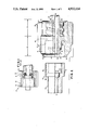
- FIG. 5 shows an apparatus for completing the assembly of the adapter of FIG. 2.
- a rotating adapter constructed in accordance with this invention includes two parts, a connector and a stem.
- the connector 20, shown in FIG. 2 prior to assembly, is generally cylindrical and is provided on its outer wall with a plurality of longitudinal fins 22. These fins are used to grasp the connector and turn it with respect to the stem, or to hold the adapter while another tube is inserted into it.
- the connector consists of two axially spaced sections 24 and 26. Section 24 is provided to mate with another tube (or any other fluid transport means). In FIG. 2, section 24 is formed to mate with a Luer connection and for this purpose it is provided with an outer collar 28 which on its inner surface is threaded as at 30. Section 24 also has an inner tapered extension 32 coaxially disposed with respect to outer collar 28. Extension 32 is provided with a longitudinal hole 34.
- Section 26 is also provided with an outer collar 36.
- This collar 36 has an inner wall 38 which is substantially cylindrical and extends longitudinally along the section. The end of collar 36 opposite section 24 is narrowed to form a ring 40. The purpose of this ring is described below.
- Section 26 also has an inner cylindrical extension 42 coaxial with collar 36. Extension 42 has a circular shoulder 44 and an inner longitudinal hole 46. Shoulder 44 divides extension 42 into two axially spaced segments 52 and 53. Segment 52 has a narrower outer diameter than segment 53. Holes 34 and 46 are aligned and continuous to form a fluid path.
- Section 26 further includes a disk-shaped wall 48 which supports extensions 32 and 42 as shown. Wall 48, collar 36 and extension 42 cooperate to form a circular groove 50.
- Stem 64 also shown in FIG. 2 comprises a tube 66 terminated in a flange 68 having an outer cylindrical wall 70.
- Tube 66 may be the extension of another device such as a manifold, a syringe or even another tube.
- Tube 66 has a longitudinal hole 72 which has approximately the same diameter as holes 34 and 46, and at the interface with flange 68, it is terminated by two inner shoulders 74 and 76 thereby defining a circular depression 78 therebetween.
- the diameter of depression 78 matches the outer diameter of segment 52 while the inner diameter of flange 68 matches the outer diameter of segment 53.
- the longitudinal length of portion 52 is larger than the axial depth of depression 78.
- flange 68 has an external shoulder 80.
- the longitudinal length of outer wall 70 on the flange matches the corresponding length of inner wall 38, excluding ring 40.
- the two longitudinal walls are complementary to prevent lateral play between the connector and the stem.
- an O-ring 82 is provided as described below.
- the two pieces of the adapter are assembled as follows. First, the connector is aligned with section 26 facing stem 64 and the O-ring 82 disposed on adapter portion 52. The two pieces are joined in an axial engagement with flange 68 disposed in groove 50 with longitudinal cylindrical walls 38 and 70 contacting each other. Thus the connector and stem are constructed and arranged such that they fit together snugly but can still rotate with respect to each other around a common axis. Importantly, when flange 68 reaches its final position in which it contacts wall 48, segment 52 is partially disposed in depression 70, however an annular space is formed between shoulders 76 and 44 to house O-ring 82. In this final position ring 40 extends past shoulder 80 on stem 64.
- the connector is now partially deformed by bending ring 40 to wrap around shoulder 80 thereby capturing the stem.
- the assembly of the adapter is illustrated in FIGS. 3 and 4.
- FIG. 3 the flange is inserted into the collar.
- FIG. 4 ring 40 is molded around the flange.
- the connector 20 has a cylindrical annular cavity terminated at its axial ends by wall 48 and ring 40 respectively for the rotatable engagement of the flange 36. Due the interaction between the outer surface 70 of the flange, and the inner surface 38 of the collar, the connector and the stem are aligned in their axial positions and resist lateral forces.
- the two ends of the cavity, i.e. the wall 48, ring 40, and groove 50 form a very stable seat for the flange and further provide a barrier for any liquid from the axial holes of the adapter.
- ring 40 is wrapped over the shoulder 80 of the flange during the final assembly. Therefore the annular cavity in the collar is matched automatically to the shape of the flange independently of any dimensional variations of the flange.
- the adapter described herein may have for example the following dimensions (in inches):
- the adapter described herein can be made of any suitable material, it is preferred that it be made of a plastic material such as a rigid engineering resin, such as compound RX 31112 or Malcrolon RX 2548 available from Mobay Chemical Company of Pittsburgh, Pennsylvania, or Lexan HP-111 available from General Electric Company. It was found that these materials, and especially RX 31112, are particularly suitable for making the adapter because they have the necessary mechanical properties, are inexpensive, and readily available off-the-shelf. Furthermore, the two pieces shown in FIG. 2 are easily made by well known molding techniques, and with a high degree of accuracy and dimensional stability. It was also found that when made from such materials the connector can be easily deformed by the application of heat to the ring 40. Another advantage of these materials is that they are colorless and highly transparent. Therefore, during a surgical procedure, the fluid flowing through the adapter can be visually inspected for air bubbles or other undesirable elements.
- a plastic material such as a rigid engineering resin, such as compound RX 31112 or Malcrolon RX 2548 available
- FIG. 5 An apparatus for assembling the parts to form the adapter is shown in FIG. 5.
- the adapter is connected to a specific device used in surgical procedures such as a MORSE® manifold 100.
- the manifold has an extension which terminates with stem 64. After the stem has been inserted into connector 20, the connector and the manifold are secured into the position shown in FIG. 5. (The means for securing the manifold have been omitted for the sake of clarity.)
- the apparatus includes a sleeve 102 which may be selectively slipped over the adapter.
- the sleeve 102 is rotatable around its axis by a motor 104 through an extension arm 106.
- the apparatus also includes a horizontal arm 108 terminating in a socket 110 which holds a forming wheel 112.
- the forming wheel is rotatable around a horizontal axis passing through the socket.
- Arm 108 is attached to a cylinder 114 provided for selectively moving the arm and the forming wheel toward and away from the adapter.
- the apparatus of FIG. 5 also includes a nozzle 116 for blowing a hot gas toward the adapter.
- the apparatus of FIG. 5 operates as follows. After the manifold 100 is secured with the adapter parts in the position shown in FIG. 5, the sleeve 102 engages the connector, with the ring 40 extending past the sleeve 102. The sleeve is then rotated by the motor 104, and the nozzle 116 moves into position to heat the ring 40. As the ring 40 is heated by hot gas from nozzle 116, the forming wheel 112 is moved horizontally to contact and press the ring in a radial direction into its final shape in which it overlaps the shoulder 80, and captures the stem 64. Importantly, while the connector 20 is continuously rotated by sleeve 106, the stem remains stationary.
- the hot gas preferably has a temperature of about 445-470 degrees F.
- the sleeve may be rotated at a speed in the range of 10-60 RPM preferably to form the ring in about 2.5-3.5 seconds.
- the rotating adapter described herein is easy and inexpensive to make, yet it has many advantageous features.
- the longitudinal walls 38 and 70 cooperate to resist any lateral forces on the adapter (i.e. forces at an angle with respect to its longitudinal axis).
- the adapter has also been found to be operative at pressures of over 1600 p.s.i. Numerous modifications may be made to the device, and the method of producing the same without departing from its scope as defined in the appended claims.
Abstract
Description
______________________________________
Overall length of connector
                     0.62
(before ring 40 is deformed)
Axial length of ring 40
                     0.05
Thickness of ring 40 0.03
(before deformation)
Length of section 24 0.27
Length of  walls  38 and 70
                     0.24
Diameter of Section 26
                     0.49
(Excluding fins 22)
Diameter of flange 68
                     0.335
______________________________________
Claims (21)
Priority Applications (2)
| Application Number | Priority Date | Filing Date | Title |
|---|---|---|---|
| US07/219,300 US4932114A (en) | 1988-07-14 | 1988-07-14 | Method of making a rotating adapter for catheters |
| US07/508,310 US5078433A (en) | 1988-07-14 | 1990-04-12 | Rotating adapter for catheters and the like |
Applications Claiming Priority (1)
| Application Number | Priority Date | Filing Date | Title |
|---|---|---|---|
| US07/219,300 US4932114A (en) | 1988-07-14 | 1988-07-14 | Method of making a rotating adapter for catheters |
Related Child Applications (1)
| Application Number | Title | Priority Date | Filing Date |
|---|---|---|---|
| US07/508,310 Division US5078433A (en) | 1988-07-14 | 1990-04-12 | Rotating adapter for catheters and the like |
Publications (1)
| Publication Number | Publication Date |
|---|---|
| US4932114A true US4932114A (en) | 1990-06-12 |
Family
ID=22818714
Family Applications (1)
| Application Number | Title | Priority Date | Filing Date |
|---|---|---|---|
| US07/219,300 Expired - Lifetime US4932114A (en) | 1988-07-14 | 1988-07-14 | Method of making a rotating adapter for catheters |
Country Status (1)
| Country | Link |
|---|---|
| US (1) | US4932114A (en) |
Cited By (36)
| Publication number | Priority date | Publication date | Assignee | Title |
|---|---|---|---|---|
| US5033655A (en) * | 1989-02-15 | 1991-07-23 | Liquid Molding Systems Inc. | Dispensing package for fluid products and the like |
| US5176662A (en) * | 1990-08-23 | 1993-01-05 | Minimed Technologies, Ltd. | Subcutaneous injection set with improved cannula mounting arrangement |
| US5176415A (en) * | 1990-08-16 | 1993-01-05 | Choksi Pradip V | Taper fitting with protective skirt |
| US5509911A (en) * | 1992-11-27 | 1996-04-23 | Maxxim Medical, Inc. | Rotating adapter for a catheterization system |
| US5549583A (en) * | 1995-08-04 | 1996-08-27 | Adam Spence Corporation | Surgical connector |
| WO1996040343A1 (en) * | 1995-06-07 | 1996-12-19 | Surgijet Corporation | Hand tightenable high pressure connector |
| US5591137A (en) * | 1995-07-14 | 1997-01-07 | Merit Medical Systems, Inc. | Hemostasis valve with locking seal |
| US5599328A (en) * | 1995-07-14 | 1997-02-04 | Merit Medical Systems, Inc. | Split ring assembly for an airless rotatable connector |
| US5601540A (en) * | 1995-07-14 | 1997-02-11 | Stevens; Brian | Apparatus for positioning a split ring over an enlarged flange |
| US5616203A (en) * | 1995-07-14 | 1997-04-01 | Merit Medical | Method of manufacturing a split ring airless rotatable connector |
| US5651170A (en) * | 1995-07-14 | 1997-07-29 | Merit Medical Systems, Inc. | Method for positioning a split ring over an enlarged flange |
| EP0786324A1 (en) * | 1996-01-24 | 1997-07-30 | B. Braun Melsungen Ag | Method of connecting a medical tube to a plastic adapter |
| US5693025A (en) * | 1995-07-14 | 1997-12-02 | Merit Medical Systems, Inc. | Adapter with hemostasis valve and rotatable connector |
| US5743571A (en) * | 1997-02-18 | 1998-04-28 | Seawin, Inc. | Fitting with floating tube support and method of manufacture |
| US5769465A (en) * | 1996-07-23 | 1998-06-23 | Bridge Products, Inc. | System for connecting a housing to a tube |
| EP0883430A1 (en) * | 1995-10-20 | 1998-12-16 | Harvest Technologies LLC | Filter bag and connector cartridge |
| US5895376A (en) * | 1996-10-23 | 1999-04-20 | Mayo Foundation For Medical Education And Research | Hemostasis valve, system and assembly |
| US5950878A (en) * | 1997-08-04 | 1999-09-14 | Steris Corporation | Dispensing tube valve assembly |
| US6134768A (en) * | 1995-07-25 | 2000-10-24 | Robert Bosch Gmbh | Method of producing connection of insert with tubular part by flanging |
| US6412170B1 (en) * | 1997-04-24 | 2002-07-02 | Siemens Aktiengesellschaft | Method of manufacturing a control flap |
| EP1225029A1 (en) * | 1999-10-14 | 2002-07-24 | Kabushiki Kaisha Top | Method of connection with synthetic resin member |
| US6536983B1 (en) * | 2000-01-20 | 2003-03-25 | Engineered Controls International Inc. | Crimp joint for pressure containing gas and fluid distribution devices |
| US20030088259A1 (en) * | 2001-08-08 | 2003-05-08 | Staid Kevin P | Medical device with high pressure quick disconnect handpiece |
| US20040172008A1 (en) * | 2002-11-19 | 2004-09-02 | Gmp/Cardiac Care, Inc. | Hemostasis valve and method of using a hemostasis valve |
| US20040260329A1 (en) * | 2003-06-19 | 2004-12-23 | Richard Gribbons | Catheter and guide wire exchange system with decoupled guide member |
| US20080086087A1 (en) * | 2004-04-16 | 2008-04-10 | Spohn Michael A | Fluid delivery system including a fluid path set with sterile check valve connector |
| US20080106097A1 (en) * | 2006-11-07 | 2008-05-08 | Brass Craft Manufacturing Company | Method of attaching tubing to a metal fitting |
| US20090051160A1 (en) * | 2007-08-20 | 2009-02-26 | Atrion Medical Products, Inc. | Bonding socket for high pressure medical hose |
| US7611503B2 (en) | 2004-04-16 | 2009-11-03 | Medrad, Inc. | Fluid delivery system, fluid path set, sterile connector and improved drip chamber and pressure isolation mechanism |
| US7717685B2 (en) | 2001-04-27 | 2010-05-18 | Hydrocision, Inc. | High pressure pumping cartridges for medical and surgical pumping and infusion applications |
| US20110092828A1 (en) * | 2004-04-16 | 2011-04-21 | Spohn Michael A | Fluid Delivery System, Fluid Path Set, and Pressure Isolation Mechanism with Hemodynamic Pressure Dampening Correction |
| US20110121558A1 (en) * | 2007-08-20 | 2011-05-26 | Atrion Medical Products, Inc. | Bonding socket for high pressure medical hose |
| US10737086B2 (en) | 2017-03-13 | 2020-08-11 | Boston Scientific Limited | Hemostasis valves and methods for making and using hemostasis valves |
| US10953214B2 (en) | 2017-09-12 | 2021-03-23 | Boston Scientific Limited | Hemostasis valves and methods for making and using hemostasis valves |
| US10960501B2 (en) | 2017-03-13 | 2021-03-30 | Boston Scientific Limited | Hemostasis valves and methods for making and using hemostasis valves |
| US11291821B2 (en) | 2017-03-13 | 2022-04-05 | Boston Scientific Limited | Hemostasis valves and methods for making and using hemostasis valves |
Citations (19)
| Publication number | Priority date | Publication date | Assignee | Title |
|---|---|---|---|---|
| US574236A (en) * | 1896-12-29 | Joseph s | ||
| US964238A (en) * | 1909-07-13 | 1910-07-12 | William H Goss | Pipe-coupling. |
| US1209374A (en) * | 1916-05-26 | 1916-12-19 | Angelo Andreolli | Hose-coupling. |
| US1241654A (en) * | 1913-10-30 | 1917-10-02 | John L Osgood | Hose-coupling. |
| US1797418A (en) * | 1924-03-06 | 1931-03-24 | John M Hothersall | Method of attaching lead spouts |
| US1804284A (en) * | 1931-05-05 | Method gb forming a display packer s | ||
| US2793912A (en) * | 1954-05-07 | 1957-05-28 | Productive Inventions Inc | Nozzle assembly |
| US2876535A (en) * | 1954-02-15 | 1959-03-10 | Gen Controls Co | Method of making packing seal for die-cast insert |
| US3042965A (en) * | 1959-10-19 | 1962-07-10 | Mueller Brass Co | Forming tool for plastic pipe |
| GB1067286A (en) * | 1965-03-16 | 1967-05-03 | Damic Controls Ltd | Improvements in hose end fittings |
| US3644874A (en) * | 1970-10-07 | 1972-02-22 | Bunker Ramo | Connector element and method for element assembly |
| US3768476A (en) * | 1972-01-27 | 1973-10-30 | Concord Labor Inc | Urinary irrigation and drainage system |
| US4123091A (en) * | 1977-11-21 | 1978-10-31 | Renal Systems, Inc. | Tube connector |
| US4254773A (en) * | 1978-11-24 | 1981-03-10 | Medex Inc. | Swivel coupling for a catheterization system |
| US4392836A (en) * | 1980-05-21 | 1983-07-12 | Kanto Seiki Co., Ltd. | Device for connecting speedometer to flexible shaft |
| US4405312A (en) * | 1981-08-31 | 1983-09-20 | Abbott Laboratories | Connecting device for medical liquid containers |
| US4542922A (en) * | 1982-02-05 | 1985-09-24 | Agro Ag. | Fitting for connecting circumferentially ribbed insulating tubes of plastic |
| US4687235A (en) * | 1985-01-11 | 1987-08-18 | Kurt Stoll | Fluid power connector fittings |
| US4714278A (en) * | 1979-09-15 | 1987-12-22 | Robert Bosch Gmbh | Plastic part provided with a metal threaded element |
-
1988
- 1988-07-14 US US07/219,300 patent/US4932114A/en not_active Expired - Lifetime
Patent Citations (19)
| Publication number | Priority date | Publication date | Assignee | Title |
|---|---|---|---|---|
| US574236A (en) * | 1896-12-29 | Joseph s | ||
| US1804284A (en) * | 1931-05-05 | Method gb forming a display packer s | ||
| US964238A (en) * | 1909-07-13 | 1910-07-12 | William H Goss | Pipe-coupling. |
| US1241654A (en) * | 1913-10-30 | 1917-10-02 | John L Osgood | Hose-coupling. |
| US1209374A (en) * | 1916-05-26 | 1916-12-19 | Angelo Andreolli | Hose-coupling. |
| US1797418A (en) * | 1924-03-06 | 1931-03-24 | John M Hothersall | Method of attaching lead spouts |
| US2876535A (en) * | 1954-02-15 | 1959-03-10 | Gen Controls Co | Method of making packing seal for die-cast insert |
| US2793912A (en) * | 1954-05-07 | 1957-05-28 | Productive Inventions Inc | Nozzle assembly |
| US3042965A (en) * | 1959-10-19 | 1962-07-10 | Mueller Brass Co | Forming tool for plastic pipe |
| GB1067286A (en) * | 1965-03-16 | 1967-05-03 | Damic Controls Ltd | Improvements in hose end fittings |
| US3644874A (en) * | 1970-10-07 | 1972-02-22 | Bunker Ramo | Connector element and method for element assembly |
| US3768476A (en) * | 1972-01-27 | 1973-10-30 | Concord Labor Inc | Urinary irrigation and drainage system |
| US4123091A (en) * | 1977-11-21 | 1978-10-31 | Renal Systems, Inc. | Tube connector |
| US4254773A (en) * | 1978-11-24 | 1981-03-10 | Medex Inc. | Swivel coupling for a catheterization system |
| US4714278A (en) * | 1979-09-15 | 1987-12-22 | Robert Bosch Gmbh | Plastic part provided with a metal threaded element |
| US4392836A (en) * | 1980-05-21 | 1983-07-12 | Kanto Seiki Co., Ltd. | Device for connecting speedometer to flexible shaft |
| US4405312A (en) * | 1981-08-31 | 1983-09-20 | Abbott Laboratories | Connecting device for medical liquid containers |
| US4542922A (en) * | 1982-02-05 | 1985-09-24 | Agro Ag. | Fitting for connecting circumferentially ribbed insulating tubes of plastic |
| US4687235A (en) * | 1985-01-11 | 1987-08-18 | Kurt Stoll | Fluid power connector fittings |
Cited By (52)
| Publication number | Priority date | Publication date | Assignee | Title |
|---|---|---|---|---|
| US5033655A (en) * | 1989-02-15 | 1991-07-23 | Liquid Molding Systems Inc. | Dispensing package for fluid products and the like |
| US5176415A (en) * | 1990-08-16 | 1993-01-05 | Choksi Pradip V | Taper fitting with protective skirt |
| US5286067A (en) * | 1990-08-16 | 1994-02-15 | Pradip Choksi | Taper fitting with protective skirt |
| US5176662A (en) * | 1990-08-23 | 1993-01-05 | Minimed Technologies, Ltd. | Subcutaneous injection set with improved cannula mounting arrangement |
| US5509911A (en) * | 1992-11-27 | 1996-04-23 | Maxxim Medical, Inc. | Rotating adapter for a catheterization system |
| US5713878A (en) * | 1995-06-07 | 1998-02-03 | Surgi-Jet Corporation | Hand tightenable high pressure connector |
| WO1996040343A1 (en) * | 1995-06-07 | 1996-12-19 | Surgijet Corporation | Hand tightenable high pressure connector |
| US5599328A (en) * | 1995-07-14 | 1997-02-04 | Merit Medical Systems, Inc. | Split ring assembly for an airless rotatable connector |
| US5601540A (en) * | 1995-07-14 | 1997-02-11 | Stevens; Brian | Apparatus for positioning a split ring over an enlarged flange |
| US5616203A (en) * | 1995-07-14 | 1997-04-01 | Merit Medical | Method of manufacturing a split ring airless rotatable connector |
| US5651170A (en) * | 1995-07-14 | 1997-07-29 | Merit Medical Systems, Inc. | Method for positioning a split ring over an enlarged flange |
| US5693025A (en) * | 1995-07-14 | 1997-12-02 | Merit Medical Systems, Inc. | Adapter with hemostasis valve and rotatable connector |
| US5591137A (en) * | 1995-07-14 | 1997-01-07 | Merit Medical Systems, Inc. | Hemostasis valve with locking seal |
| US6134768A (en) * | 1995-07-25 | 2000-10-24 | Robert Bosch Gmbh | Method of producing connection of insert with tubular part by flanging |
| US5549583A (en) * | 1995-08-04 | 1996-08-27 | Adam Spence Corporation | Surgical connector |
| EP0883430A4 (en) * | 1995-10-20 | 2000-04-26 | Harvest Technologies Corp | Filter bag and connector cartridge |
| EP1738782A1 (en) * | 1995-10-20 | 2007-01-03 | Haemonetics Corporation | Filter bag |
| US6325422B1 (en) | 1995-10-20 | 2001-12-04 | Harvest Technologies Corporation | Filter bag and connector cartridge |
| EP0883430A1 (en) * | 1995-10-20 | 1998-12-16 | Harvest Technologies LLC | Filter bag and connector cartridge |
| EP0786324A1 (en) * | 1996-01-24 | 1997-07-30 | B. Braun Melsungen Ag | Method of connecting a medical tube to a plastic adapter |
| US5769465A (en) * | 1996-07-23 | 1998-06-23 | Bridge Products, Inc. | System for connecting a housing to a tube |
| US5895376A (en) * | 1996-10-23 | 1999-04-20 | Mayo Foundation For Medical Education And Research | Hemostasis valve, system and assembly |
| US6221057B1 (en) | 1996-10-23 | 2001-04-24 | Mayo Foundation For Medical Education And Research | Hemostasis valve, system and assembly |
| US5743571A (en) * | 1997-02-18 | 1998-04-28 | Seawin, Inc. | Fitting with floating tube support and method of manufacture |
| US6412170B1 (en) * | 1997-04-24 | 2002-07-02 | Siemens Aktiengesellschaft | Method of manufacturing a control flap |
| US5950878A (en) * | 1997-08-04 | 1999-09-14 | Steris Corporation | Dispensing tube valve assembly |
| EP1225029A4 (en) * | 1999-10-14 | 2002-11-04 | Top Kk | Method of connection with synthetic resin member |
| AU767795B2 (en) * | 1999-10-14 | 2003-11-27 | Kabushiki Kaisha Top | Method of connection with synthetic resin member |
| US7198746B1 (en) | 1999-10-14 | 2007-04-03 | Kabushiki Kaisha Top | Method of connection with synthetic resin member |
| EP1225029A1 (en) * | 1999-10-14 | 2002-07-24 | Kabushiki Kaisha Top | Method of connection with synthetic resin member |
| US6536983B1 (en) * | 2000-01-20 | 2003-03-25 | Engineered Controls International Inc. | Crimp joint for pressure containing gas and fluid distribution devices |
| US8851866B2 (en) | 2001-04-27 | 2014-10-07 | Hydrocision, Inc. | Methods and apparatuses for joining a pumping cartridge to a pump drive |
| US7717685B2 (en) | 2001-04-27 | 2010-05-18 | Hydrocision, Inc. | High pressure pumping cartridges for medical and surgical pumping and infusion applications |
| US20050267443A1 (en) * | 2001-08-08 | 2005-12-01 | Hydrocision, Inc. | Medical device with high pressure quick disconnect handpiece |
| US6923792B2 (en) | 2001-08-08 | 2005-08-02 | Hydrocision, Inc. | Medical device with high pressure quick disconnect handpiece |
| US7951107B2 (en) | 2001-08-08 | 2011-05-31 | Hydrocision, Inc. | Medical device with high pressure quick disconnect handpiece |
| US20030088259A1 (en) * | 2001-08-08 | 2003-05-08 | Staid Kevin P | Medical device with high pressure quick disconnect handpiece |
| US20040172008A1 (en) * | 2002-11-19 | 2004-09-02 | Gmp/Cardiac Care, Inc. | Hemostasis valve and method of using a hemostasis valve |
| US20040260329A1 (en) * | 2003-06-19 | 2004-12-23 | Richard Gribbons | Catheter and guide wire exchange system with decoupled guide member |
| US8992489B2 (en) | 2004-04-16 | 2015-03-31 | Bayer Medical Care Inc. | Fluid delivery system, fluid path set, and pressure isolation mechanism with hemodynamic pressure dampening correction |
| US20080086087A1 (en) * | 2004-04-16 | 2008-04-10 | Spohn Michael A | Fluid delivery system including a fluid path set with sterile check valve connector |
| US7611503B2 (en) | 2004-04-16 | 2009-11-03 | Medrad, Inc. | Fluid delivery system, fluid path set, sterile connector and improved drip chamber and pressure isolation mechanism |
| US20110092828A1 (en) * | 2004-04-16 | 2011-04-21 | Spohn Michael A | Fluid Delivery System, Fluid Path Set, and Pressure Isolation Mechanism with Hemodynamic Pressure Dampening Correction |
| US9895527B2 (en) | 2004-04-16 | 2018-02-20 | Bayer Healthcare Llc | Fluid delivery system, fluid path set, and pressure isolation mechanism with hemodynamic pressure dampening correction |
| US8540698B2 (en) | 2004-04-16 | 2013-09-24 | Medrad, Inc. | Fluid delivery system including a fluid path set and a check valve connector |
| US20080106097A1 (en) * | 2006-11-07 | 2008-05-08 | Brass Craft Manufacturing Company | Method of attaching tubing to a metal fitting |
| US20090051160A1 (en) * | 2007-08-20 | 2009-02-26 | Atrion Medical Products, Inc. | Bonding socket for high pressure medical hose |
| US20110121558A1 (en) * | 2007-08-20 | 2011-05-26 | Atrion Medical Products, Inc. | Bonding socket for high pressure medical hose |
| US10737086B2 (en) | 2017-03-13 | 2020-08-11 | Boston Scientific Limited | Hemostasis valves and methods for making and using hemostasis valves |
| US10960501B2 (en) | 2017-03-13 | 2021-03-30 | Boston Scientific Limited | Hemostasis valves and methods for making and using hemostasis valves |
| US11291821B2 (en) | 2017-03-13 | 2022-04-05 | Boston Scientific Limited | Hemostasis valves and methods for making and using hemostasis valves |
| US10953214B2 (en) | 2017-09-12 | 2021-03-23 | Boston Scientific Limited | Hemostasis valves and methods for making and using hemostasis valves |
Similar Documents
| Publication | Publication Date | Title |
|---|---|---|
| US4932114A (en) | Method of making a rotating adapter for catheters | |
| US5078433A (en) | Rotating adapter for catheters and the like | |
| EP0098103B1 (en) | Medical connector | |
| CA1167212A (en) | Method of connecting plastic tube to a plastic part | |
| US4254773A (en) | Swivel coupling for a catheterization system | |
| US8241256B2 (en) | Needle guide for needle-based medical device | |
| US5456676A (en) | Rotatable bubble-free connector | |
| US4592749A (en) | Catheter system | |
| CA1272093A (en) | Backform inserts for catheter | |
| US5129887A (en) | Adjustable manifold for dilatation catheter | |
| CA2001057C (en) | Catheter equipped with expansible member and method of manufacturing the same | |
| EP2422837B1 (en) | Medical connector structure | |
| US20010000061A1 (en) | Pressure transmission apparatus | |
| JPH0339673Y2 (en) | ||
| CA1232504A (en) | Tube and fitting assembly and method of making same | |
| US9481118B2 (en) | Medical access device | |
| GB1587018A (en) | Plastics socket pipe part and method of manufacturing same | |
| US5549865A (en) | Method for manufacture of an elastomeric tube coupling body | |
| CA1202340A (en) | Swivel coupling | |
| JPH0150797B2 (en) | ||
| US5279592A (en) | Catheter for medical use | |
| WO2022021485A1 (en) | Medical catheter | |
| CN219501834U (en) | Three-way transfusion joint | |
| JPH02142992A (en) | Coupling for coupling pipe | |
| US4252117A (en) | Injection device |
Legal Events
| Date | Code | Title | Description |
|---|---|---|---|
| AS | Assignment |
Owner name: NORTH AMERICAN INSTRUMENT CORP. Free format text: ASSIGNMENT OF ASSIGNORS INTEREST.;ASSIGNORS:MORSE, PHILLIP H.;MORRIS, CYNTHIA L.;WEST, RONALD L.;REEL/FRAME:004957/0211 Effective date: 19880916 |
|
| STCF | Information on status: patent grant |
Free format text: PATENTED CASE |
|
| FPAY | Fee payment |
Year of fee payment: 4 |
|
| FEPP | Fee payment procedure |
Free format text: PAYOR NUMBER ASSIGNED (ORIGINAL EVENT CODE: ASPN); ENTITY STATUS OF PATENT OWNER: LARGE ENTITY |
|
| FEPP | Fee payment procedure |
Free format text: PAT HLDR NO LONGER CLAIMS SMALL ENT STAT AS SMALL BUSINESS (ORIGINAL EVENT CODE: LSM2); ENTITY STATUS OF PATENT OWNER: LARGE ENTITY |
|
| FPAY | Fee payment |
Year of fee payment: 8 |
|
| AS | Assignment |
Owner name: SCHNEIDER/NAMIC, NEW YORK Free format text: ASSIGNMENT OF ASSIGNORS INTEREST;ASSIGNOR:NORTH AMERICA INSTRUMENT CORP.;REEL/FRAME:009453/0559 Effective date: 19971124 |
|
| FPAY | Fee payment |
Year of fee payment: 12 |
|
| AS | Assignment |
Owner name: BOSTON SCIENTIFIC GLENS FALLS CORP., NEW YORK Free format text: CHANGE OF NAME;ASSIGNOR:SCHNEIDER/NAMIC;REEL/FRAME:018454/0820 Effective date: 20040122 |
|
| AS | Assignment |
Owner name: GENERAL ELECTRIC CAPITAL CORPORATION, AS ADMINISTR Free format text: SECURITY AGREEMENT;ASSIGNOR:NAMIC / VA, INC.;REEL/FRAME:020507/0952 Effective date: 20080214 |
|
| AS | Assignment |
Owner name: GENERAL ELECTRIC CAPITAL CORPORATION, AS ADMINISTR Free format text: SECURITY AGREEMENT;ASSIGNOR:NAMIC / VA, INC.;REEL/FRAME:020540/0726 Effective date: 20080214 |
|
| AS | Assignment |
Owner name: NAMIC/VA, INC., MASSACHUSETTS Free format text: ASSIGNMENT OF ASSIGNORS INTEREST;ASSIGNOR:BOSTON SCIENTIFIC GLEN FALLS CORPORATION;REEL/FRAME:020599/0881 Effective date: 20080212 |
|
| AS | Assignment |
Owner name: NAVILYST MEDICAL, INC. (F/K/A NAMIC/VA, INC.), MAS Free format text: RELEASE OF SECURITY INTEREST RECORDED AT REEL/FRAME 20507/952;ASSIGNOR:GENERAL ELECTRIC CAPITAL CORPORATION, AS ADMINISTRATIVE AGENT;REEL/FRAME:028273/0944 Effective date: 20120522 Owner name: NAVILYST MEDICAL, INC. (F/K/A NAMIC/VA, INC.), MAS Free format text: RELEASE OF SECURITY INTEREST RECORDED AT REEL/FRAME 20540/726;ASSIGNOR:GENERAL ELECTRIC CAPITAL CORPORATION, AS ADMINISTRATIVE AGENT;REEL/FRAME:028273/0958 Effective date: 20120522 |