US4934785A - Optical fiber connector - Google Patents
Optical fiber connector Download PDFInfo
- Publication number
- US4934785A US4934785A US07/314,683 US31468389A US4934785A US 4934785 A US4934785 A US 4934785A US 31468389 A US31468389 A US 31468389A US 4934785 A US4934785 A US 4934785A
- Authority
- US
- United States
- Prior art keywords
- fiber
- base
- optical fiber
- connector
- plug
- Prior art date
- Legal status (The legal status is an assumption and is not a legal conclusion. Google has not performed a legal analysis and makes no representation as to the accuracy of the status listed.)
- Expired - Lifetime
Links
Images


Classifications
-
- G—PHYSICS
- G02—OPTICS
- G02B—OPTICAL ELEMENTS, SYSTEMS OR APPARATUS
- G02B6/00—Light guides; Structural details of arrangements comprising light guides and other optical elements, e.g. couplings
- G02B6/24—Coupling light guides
- G02B6/26—Optical coupling means
- G02B6/35—Optical coupling means having switching means
- G02B6/3502—Optical coupling means having switching means involving direct waveguide displacement, e.g. cantilever type waveguide displacement involving waveguide bending, or displacing an interposed waveguide between stationary waveguides
- G02B6/3504—Rotating, tilting or pivoting the waveguides, or with the waveguides describing a curved path
-
- G—PHYSICS
- G02—OPTICS
- G02B—OPTICAL ELEMENTS, SYSTEMS OR APPARATUS
- G02B6/00—Light guides; Structural details of arrangements comprising light guides and other optical elements, e.g. couplings
- G02B6/24—Coupling light guides
- G02B6/26—Optical coupling means
- G02B6/264—Optical coupling means with optical elements between opposed fibre ends which perform a function other than beam splitting
- G02B6/266—Optical coupling means with optical elements between opposed fibre ends which perform a function other than beam splitting the optical element being an attenuator
-
- G—PHYSICS
- G02—OPTICS
- G02B—OPTICAL ELEMENTS, SYSTEMS OR APPARATUS
- G02B6/00—Light guides; Structural details of arrangements comprising light guides and other optical elements, e.g. couplings
- G02B6/24—Coupling light guides
- G02B6/26—Optical coupling means
- G02B6/35—Optical coupling means having switching means
- G02B6/3502—Optical coupling means having switching means involving direct waveguide displacement, e.g. cantilever type waveguide displacement involving waveguide bending, or displacing an interposed waveguide between stationary waveguides
- G02B6/3506—Translating the waveguides along the beam path, e.g. by varying the distance between opposed waveguide ends, or by translation of the waveguide ends
-
- G—PHYSICS
- G02—OPTICS
- G02B—OPTICAL ELEMENTS, SYSTEMS OR APPARATUS
- G02B6/00—Light guides; Structural details of arrangements comprising light guides and other optical elements, e.g. couplings
- G02B6/24—Coupling light guides
- G02B6/36—Mechanical coupling means
- G02B6/38—Mechanical coupling means having fibre to fibre mating means
- G02B6/3807—Dismountable connectors, i.e. comprising plugs
- G02B6/381—Dismountable connectors, i.e. comprising plugs of the ferrule type, e.g. fibre ends embedded in ferrules, connecting a pair of fibres
- G02B6/3818—Dismountable connectors, i.e. comprising plugs of the ferrule type, e.g. fibre ends embedded in ferrules, connecting a pair of fibres of a low-reflection-loss type
- G02B6/382—Dismountable connectors, i.e. comprising plugs of the ferrule type, e.g. fibre ends embedded in ferrules, connecting a pair of fibres of a low-reflection-loss type with index-matching medium between light guides
-
- G—PHYSICS
- G02—OPTICS
- G02B—OPTICAL ELEMENTS, SYSTEMS OR APPARATUS
- G02B6/00—Light guides; Structural details of arrangements comprising light guides and other optical elements, e.g. couplings
- G02B6/24—Coupling light guides
- G02B6/36—Mechanical coupling means
- G02B6/38—Mechanical coupling means having fibre to fibre mating means
- G02B6/3807—Dismountable connectors, i.e. comprising plugs
- G02B6/381—Dismountable connectors, i.e. comprising plugs of the ferrule type, e.g. fibre ends embedded in ferrules, connecting a pair of fibres
- G02B6/3818—Dismountable connectors, i.e. comprising plugs of the ferrule type, e.g. fibre ends embedded in ferrules, connecting a pair of fibres of a low-reflection-loss type
- G02B6/3821—Dismountable connectors, i.e. comprising plugs of the ferrule type, e.g. fibre ends embedded in ferrules, connecting a pair of fibres of a low-reflection-loss type with axial spring biasing or loading means
-
- G—PHYSICS
- G02—OPTICS
- G02B—OPTICAL ELEMENTS, SYSTEMS OR APPARATUS
- G02B6/00—Light guides; Structural details of arrangements comprising light guides and other optical elements, e.g. couplings
- G02B6/24—Coupling light guides
- G02B6/36—Mechanical coupling means
- G02B6/38—Mechanical coupling means having fibre to fibre mating means
- G02B6/3807—Dismountable connectors, i.e. comprising plugs
- G02B6/3833—Details of mounting fibres in ferrules; Assembly methods; Manufacture
- G02B6/3834—Means for centering or aligning the light guide within the ferrule
- G02B6/3835—Means for centering or aligning the light guide within the ferrule using discs, bushings or the like
-
- G—PHYSICS
- G02—OPTICS
- G02B—OPTICAL ELEMENTS, SYSTEMS OR APPARATUS
- G02B6/00—Light guides; Structural details of arrangements comprising light guides and other optical elements, e.g. couplings
- G02B6/24—Coupling light guides
- G02B6/36—Mechanical coupling means
- G02B6/38—Mechanical coupling means having fibre to fibre mating means
- G02B6/3807—Dismountable connectors, i.e. comprising plugs
- G02B6/3873—Connectors using guide surfaces for aligning ferrule ends, e.g. tubes, sleeves, V-grooves, rods, pins, balls
- G02B6/3874—Connectors using guide surfaces for aligning ferrule ends, e.g. tubes, sleeves, V-grooves, rods, pins, balls using tubes, sleeves to align ferrules
- G02B6/3877—Split sleeves
-
- G—PHYSICS
- G02—OPTICS
- G02B—OPTICAL ELEMENTS, SYSTEMS OR APPARATUS
- G02B6/00—Light guides; Structural details of arrangements comprising light guides and other optical elements, e.g. couplings
- G02B6/24—Coupling light guides
- G02B6/36—Mechanical coupling means
- G02B6/38—Mechanical coupling means having fibre to fibre mating means
- G02B6/3807—Dismountable connectors, i.e. comprising plugs
- G02B6/389—Dismountable connectors, i.e. comprising plugs characterised by the method of fastening connecting plugs and sockets, e.g. screw- or nut-lock, snap-in, bayonet type
-
- G—PHYSICS
- G02—OPTICS
- G02B—OPTICAL ELEMENTS, SYSTEMS OR APPARATUS
- G02B6/00—Light guides; Structural details of arrangements comprising light guides and other optical elements, e.g. couplings
- G02B6/24—Coupling light guides
- G02B6/26—Optical coupling means
- G02B6/28—Optical coupling means having data bus means, i.e. plural waveguides interconnected and providing an inherently bidirectional system by mixing and splitting signals
- G02B6/293—Optical coupling means having data bus means, i.e. plural waveguides interconnected and providing an inherently bidirectional system by mixing and splitting signals with wavelength selective means
- G02B6/29346—Optical coupling means having data bus means, i.e. plural waveguides interconnected and providing an inherently bidirectional system by mixing and splitting signals with wavelength selective means operating by wave or beam interference
- G02B6/29361—Interference filters, e.g. multilayer coatings, thin film filters, dichroic splitters or mirrors based on multilayers, WDM filters
- G02B6/29368—Light guide comprising the filter, e.g. filter deposited on a fibre end
-
- G—PHYSICS
- G02—OPTICS
- G02B—OPTICAL ELEMENTS, SYSTEMS OR APPARATUS
- G02B6/00—Light guides; Structural details of arrangements comprising light guides and other optical elements, e.g. couplings
- G02B6/24—Coupling light guides
- G02B6/26—Optical coupling means
- G02B6/35—Optical coupling means having switching means
- G02B6/354—Switching arrangements, i.e. number of input/output ports and interconnection types
- G02B6/3544—2D constellations, i.e. with switching elements and switched beams located in a plane
- G02B6/3548—1xN switch, i.e. one input and a selectable single output of N possible outputs
- G02B6/355—1x2 switch, i.e. one input and a selectable single output of two possible outputs
-
- G—PHYSICS
- G02—OPTICS
- G02B—OPTICAL ELEMENTS, SYSTEMS OR APPARATUS
- G02B6/00—Light guides; Structural details of arrangements comprising light guides and other optical elements, e.g. couplings
- G02B6/24—Coupling light guides
- G02B6/26—Optical coupling means
- G02B6/35—Optical coupling means having switching means
- G02B6/354—Switching arrangements, i.e. number of input/output ports and interconnection types
- G02B6/3544—2D constellations, i.e. with switching elements and switched beams located in a plane
- G02B6/3548—1xN switch, i.e. one input and a selectable single output of N possible outputs
- G02B6/3552—1x1 switch, e.g. on/off switch
-
- G—PHYSICS
- G02—OPTICS
- G02B—OPTICAL ELEMENTS, SYSTEMS OR APPARATUS
- G02B6/00—Light guides; Structural details of arrangements comprising light guides and other optical elements, e.g. couplings
- G02B6/24—Coupling light guides
- G02B6/26—Optical coupling means
- G02B6/35—Optical coupling means having switching means
- G02B6/3564—Mechanical details of the actuation mechanism associated with the moving element or mounting mechanism details
- G02B6/3582—Housing means or package or arranging details of the switching elements, e.g. for thermal isolation
-
- G—PHYSICS
- G02—OPTICS
- G02B—OPTICAL ELEMENTS, SYSTEMS OR APPARATUS
- G02B6/00—Light guides; Structural details of arrangements comprising light guides and other optical elements, e.g. couplings
- G02B6/24—Coupling light guides
- G02B6/26—Optical coupling means
- G02B6/35—Optical coupling means having switching means
- G02B6/3594—Characterised by additional functional means, e.g. means for variably attenuating or branching or means for switching differently polarized beams
-
- G—PHYSICS
- G02—OPTICS
- G02B—OPTICAL ELEMENTS, SYSTEMS OR APPARATUS
- G02B6/00—Light guides; Structural details of arrangements comprising light guides and other optical elements, e.g. couplings
- G02B6/24—Coupling light guides
- G02B6/36—Mechanical coupling means
- G02B6/38—Mechanical coupling means having fibre to fibre mating means
- G02B6/3807—Dismountable connectors, i.e. comprising plugs
- G02B6/3873—Connectors using guide surfaces for aligning ferrule ends, e.g. tubes, sleeves, V-grooves, rods, pins, balls
- G02B6/3874—Connectors using guide surfaces for aligning ferrule ends, e.g. tubes, sleeves, V-grooves, rods, pins, balls using tubes, sleeves to align ferrules
- G02B6/3878—Connectors using guide surfaces for aligning ferrule ends, e.g. tubes, sleeves, V-grooves, rods, pins, balls using tubes, sleeves to align ferrules comprising a plurality of ferrules, branching and break-out means
-
- G—PHYSICS
- G02—OPTICS
- G02B—OPTICAL ELEMENTS, SYSTEMS OR APPARATUS
- G02B6/00—Light guides; Structural details of arrangements comprising light guides and other optical elements, e.g. couplings
- G02B6/24—Coupling light guides
- G02B6/36—Mechanical coupling means
- G02B6/38—Mechanical coupling means having fibre to fibre mating means
- G02B6/3807—Dismountable connectors, i.e. comprising plugs
- G02B6/3898—Tools, e.g. handheld; Tuning wrenches; Jigs used with connectors, e.g. for extracting, removing or inserting in a panel, for engaging or coupling connectors, for assembling or disassembling components within the connector, for applying clips to hold two connectors together or for crimping
Definitions
- This invention pertains to splices and connectors for optical fiber.
- Optical fiber connectors and splices are an essential part of substantially any optical fiber communication system.
- connectors may be used to join segments of fiber into longer lengths, or to connect fiber to active devices such as radiation sources, detectors, or repeaters, or to passive devices such as switches or attenuators.
- an optical fiber connector The task of an optical fiber connector is twofold. First, it must couple or join two optical fibers with minimum insertion loss. Second, it must provide mechanical stability and protection to the junction in its working environment. Achieving low insertion loss in coupling two fibers is generally a function of the alignment of the fiber ends, the width of the gap between the ends, and the optical surface condition of either or both ends. Stability and junction protection is generally a function of connector design, e.g., minimization of differential thermal expansion effects.
- U.S. Pat. No. 4,205,897 issued June 3, 1980 to W. C. Stankos, for "Fiber Optic Connector for Single Fiber,” discloses a connector and coupling assembly for coupling a single pair of optical fibers in which the respective fibers are secured in identical metallic connector pins inserted into an alignment sleeve having a precision axial aperture.
- U.S. Pat. No. 4,135,781 issued Jan. 23, 1979, to J. D.
- Archer for "Optical Fiber Termination" discloses a method for terminating an optical fiber by means of a connector by pushing the plastic-clad optical fiber into a heater ferrule containing a pierced watch bearing jewel, so as to force the bare fiber through the aperture in the jewel, then fusing the protruding fiber end, and polishing the fused fiber end flush with the jewel surface.
- the connector described therein comprises a glass tube, factory-bonded to a metallic connector body assembly. Stripped fiber is threaded through the bore of the glass tube, and held in place therein by means of UV-curable adhesive. A metal ferrule is slipped over the length of fiber jutting from the glass tube/body assembly and held in place by means of a coupling ring. The fiber end protruding from the slightly concave ferrule surface is scribed and broken close to the ferrule. The ferrule can then be inserted without further processing into a mating bushing of an appropriate adapter or receptacle to complete a connection.
- Prior art optical fiber connectors typically contain one or more precision machined parts and are therefore relatively costly items. Whereas this may be acceptable for some applications, e.g., in trunk lines, in other cases the price of connectors of the prior art type might constitute a significant fraction of the total installation price.
- An example of such an installation is considered to be a local area network (LAN), which usually would require many, perhaps hundreds, of fiber connectors.
- LAN local area network
- a further and very important consideration is the relative ease of field installation of an optical fiber connector, since a complicated and lengthy installation procedure may significantly affect the installed price of a multiconnector optical fiber network. It is thus desirable that the installation of a connector not only be accomplishable within a relatively short period of time but also that the installation not require special skills, or manipulations not easily carried out in the field.
- optical fiber connector whose parts can be easily and inexpensively produced, which can be quickly and simply installed by relatively unskilled personnel in the field, and which, furthermore, is compatible with all environmental conditions it is likely to encounter, and which has extremely low insertion loss, would be of great commercial importance.
- This application discloses such an optical fiber connector.
- the inventive optical fiber connector is a device for abuttingly joining one optical fiber to another optical fiber.
- the connectors can assume a variety of forms, including the form of multichannel connectors, and is useful for connecting single mode fiber as well as for connecting multimode fiber.
- the principle of the inventive device can be embodied in other fiber-optic devices, e.g., a variable attenuator, a fiber-to-fiber switch, or a simple in-line optical fiber.
- a complete connector according to the invention comprises two drawn capillary glass right circular cylinders, each cylinder having a "free" end face, alignment means, acting on the outside surfaces of the cylinders, for maintaining the cylinders in radially fixed relation to each other, and axial spring means for maintaining the free end faces of the cylinders in fixed axial relation to each other.
- a connection is made by inserting the bared end of a fiber into the capillary bore of a cylinder, threading it through the length of the cylinder, followed by fixing the fiber in the capillary bore by appropriate (e.g., adhesive) means, and preparing the fiber end to be flush with the free end face of the cylinder, e.g., by grinding and/or polishing.
- Two similarly prepared cylinders are then maintained in radially and axially fixed relationship by the above-mentioned means, such as to permit at least a substantial fraction of electromagnetic radiation emitted from one fiber end to couple into the second fiber end.
- the inventive connector contains only one type of precision element, namely, the two drawn capillary glass cylinders. This element can be easily and cheaply manufactured to within close tolerances.
- the fiber preferably fits relatively loosely into the capillary bore (diameter difference preferably between about 0.5 ⁇ m and about 5 ⁇ m), since the adhesive material typically filling the space between fiber and capillary wall apparently can exert a dynamic centering effect on the fiber during fiber insertion, resulting in an accurately concentric assembly.
- FIG. 1 shows an exemplary as-drawn and cut glass capillary cylinder
- FIG. 2 depicts an exemplary chamfered and insertion-coned glass capillary cylinder
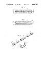
- FIG. 3 gives in exploded view the parts of a connector according to the invention
- FIG. 4 shows in partial cross-section an assembled exemplary connector according to the invention
- FIG. 5 illustrates a further exemplary embodiment of the invention, namely, a feed-through connector of the twist-and-lock type
- FIG. 6 gives exemplary experimentally obtained data on connector insertion loss vs. cylinder end face separation
- FIG. 7 shows schematically an embodiment of the invention adapted to function as a variable attenuator
- FIG. 8 shows schematically an embodiment of the invention adapted to function as a fiber-to-fiber switch.
- One of the central aspects of this invention is the use of drawn glass capillary cylinders as the sole precision elements in a optical fiber connector.
- Methods for "drawing down" tubular glass preforms, to thereby produce a reduced-cross-section replica of the preform as well known in the art and need no detailed exposition. It will, for instance, be readily apparent to those skilled in the art that the preform has to have substantially the same ratio of outer to inner diameter as the capillary cylinder. To achieve the required dimensions on the finished part, it may be necessary to change the outside diameter of an available glass tube by grinding, or to employ other appropriate procedures for achieving the required ratio in the preform.
- a critical parameter of a glass capillary cylinder for use in a connector according to the invention is the bore eccentricity, which should be as small as possible, typically less than about 5 percent, preferably less than 2 percent.
- Bore eccentricity herein is defined as ⁇ /a, where a is the capillary bore radius, and ⁇ the concentricity error, i.e., the amount by which the bore axis is shifted from the cylinder axis.
- FIG. 1 shows in cross-section an exemplary glass capillary cylinder substantially as drawn and then cut from the drawn capillary tube.
- the cylinder can consist of any appropriate glass, e.g., PYREX, quartz, borosilicate or soda-lime glass.
- FIG. 2 An exemplary capillary cylinder suitable for incorporation into a connector according to the invention is shown in cross-section in FIG. 2.
- End faces 20 and 21 are prepared, e.g., by cutting or grinding, to be substantially perpendicular to the cylinder axis.
- Fiber insertion into the bore is aided by means of fiber entry cone 22.
- Chamfer 23, as well as cone 22 can be produced by any appropriate means, e.g., by grinding, etching, or fire polishing. Presence of a fiber entry cone is not always necessary in the glass cylinder, since other ways of ensuring easy fiber into the capillary bore exist, e.g., an entry cone in the bore of the connector base.
- a complete fiber connection according to the invention comprises, in addition to the two drawn glass capillary cylinders (which are not necessarily of equal length, but typically and closely matched in OD and bore diameter), alignment means for maintaining the cylinders substantially radially fixed with respect to each other.
- alignment means for maintaining the cylinders substantially radially fixed with respect to each other.
- An inventive connection also comprises means, typically comprising an elastically deformable body, e.g., a spring, for maintaining the two glass cylinders in axially fixed relation with each other.
- This relation is, at least in the case of a simple connector, a contacting one (with or without the presence of a thin layer of index-matching material between the free end faces).
- the free end faces of the two cylinders are maintained in contacting relationship by means of an axially applied force.
- a simple mounting clip made of phosphor bronze, steel, plastic, or any other appropriate material, can perform this function.
- FIG. 3 shows, in exploded view, parts of a simple connector according to the invention, with glass cylinders 10 to be held in radially fixed relation by split alignment sleeve 30, and in axially fixed relation, in this case contacting relation, by mounting clip 31.
- Connector bases 32 serve, inter alia, to hold (in bore 34) the coated fiber in fixed relationship with respect to the connector, thereby reducing stress on the bare fiber end, and to provide means for applying the axial-position-maintaining force, e.g., shoulder 33.
- the connector base typically is a low precision part, e.g., an aluminum screw machine part, or an injection molded plastic part.
- the base advantageously provides centering means for the coated fiber. This can be achieved, for instance, by providing a relatively close fit between the coated fiber and the bore of the base.
- a connector according to the invention can be assembled by, for instance, inserting an appropriately prepared drawn glass cylinder into a connector base, and attaching it permanently thereto, e.g., by means of epoxy, press-fit, or UV-curable adhesive (e.g., a diacrylate adhesive such as ACE 7515, manufactured by American Chemical Engineering Company).
- the base advantageously is fabricated from UV-transmitting material, e.g., polymethylmethacrylate (PMMA) or quartz.
- the coating is stripped from the end of a fiber, an appropriate adhesive (e.g., UV-curable or fast-curing epoxy) injected into the connector base, the stripped fiber end inserted through the base into the glass cylinder, and pushed forward until the fiber end emerges from the free end face of the cylinder and the coated fiber extends into the connector base.
- an appropriate adhesive e.g., UV-curable or fast-curing epoxy
- the protruding piece of fiber is removed (e.g., by scribing and breaking) and the fiber end polished flush with the base, for instance, by polishing on 8 ⁇ m, followed by 1 ⁇ m, polishing paper.
- the connector can be completed by inserting both assemblies into an alignment sleeve, with or without index matching material (e.g., silicone gel) between the opposing end faces, and inserting the combination into a mounting clip.
- FIG. 4 An assembled exemplary inventive connector is shown in partial cutaway view in FIG. 4.
- Coated optical fiber 40 is inserted into connector base 32, preferably as far as insertion cone 42, with bare optical fiber 41 extending through glass cylinder 10.
- Adhesive is introduced into the base through bore 34.
- the assembled connector can be mounted on a solid object 43, e.g., a wall, by means of mounting clip 31.
- the adhesive introduced into the connector base is typically drawn into the bore of the glass cylinder, where its presence appears to have a dynamic centering effect when the fiber is inserted into the bore.
- the bore diameter 2a preferably exceed the diameter of the bare optical fiber by at least about 0.5 ⁇ m, but preferably by not more than about 5 ⁇ m.
- FIG. 5 An example of a panel-mountable twist-and-lock type connector (i.e., a connector adapted for feeding a fiber channel through a panel or, more generally, a part of a solid object), is shown in FIG. 5.
- a single fiber cable 40 is held fixed in cable retainer and connector base 32, with the bare glass fiber inserted into drawn glass capillary cylinder 10 and extending therethrough, the capillary cylinder being maintained in fixed relation with respect to 32 by, e.g., adhesive means.
- the bare fiber and the cable are also typically maintained in fixed relation with respect to 10 and 32, respectively, by adhesive means.
- the above-described cable-terminating assembly is inserted into cap 51 and retained therein by means of retaining rings 56 and 52, with spring 54, acting against washer 55, providing axial force for maintaining the free end faces of glass cylinders 10 firmly in contact in the assembled connector.
- Panel mount 57 is typically affixed to a panel or the like by means of screws extending through openings 58. Into 57's central bore is inserted alignment sleeve 30, and maintained therein by sleeve retainer 50.
- the two cable-terminating assemblies to be joined are very similar, the major difference between them being the fact that only one assembly comprises spring 54, spacer 59 taking its place in the second assembly.
- an inventive connector of the type exemplified by FIG. 5 could be constructed to be completely symmetrical, or to differ in symmetry to a greater extent than the exemplary depicted embodiment.
- one of the glass cylinders e.g., the one forming part of the "left-hand" assembly of FIG. 5, is inserted into sleeve 30, and the left-hand assembly is attached to 57 by means of the twist-and-lock arrangement depicted.
- the right-hand glass cylinder is inserted into 30, and the assembly secured as above, with spring 54 not only serving to maintain the glass cylinder end faces pressed against each other but also providing locking compression on the two twist-and-lock connections of the connector assembly.
- FIG. 6 shows experimentally obtained data on connector loss as a function of capillary cylinder end face separation.
- the insertion loss is a strong function of end face separation in a connector according to the invention, attenuation in db increasing typically linearly with the logarithm of the separation above some separation, in the exemplary data, above about 0.4 mm separation.
- FIG. 7 is intended to illustrate, by means of a simple and workable embodiment, the principle of a variable attenuator according to the invention. Those skilled in the art will be readily able to devise other embodiments of the invention, based on the principles disclosed herein.
- optical filter material can be placed between the opposing end faces of the two glass cylinders, either in the basic connector assembly (exemplified in FIG. 4), in other connector configurations (e.g., as exemplified in FIG. 5), or in adaptations of the invention, e.g., as the variable attenuator exemplified in FIG. 7.
- Such a filter could be used to improve the spectral purity of a signal, or to isolate a signal in a wavelength-multiplexed optical communication system.
- FIG. 8 A further embodiment of the inventive connector, namely, a 1 ⁇ 2 fiber-to-fiber switch, is depicted schematically in FIG. 8.
- Connector bases 32a and 32b are mounted in switch housing 43, and base 32c is movably held inside the housing.
- Capillary cylinders 10 are attached to the bases, coated fibers 40 mounted, and bared fiber ends prepared, as described above.
- Base 32c is mounted in link 80, part of a 4-bar mechanism (further comprising bars 81 and 82, and pins 83-86) attached to the switch housing.
- This arrangement allows insertion of the moving capillary cylinder 10 either into alignment sleeve 30a or 30b.
- Means for attaching the 4-bar mechanism to the housing, means for maintaining the appropriate axial relation between the abutting capillary cylinders, means for activating switch movement, and the like, can be conventional and are not shown.
- connectors according to the invention utilized mechanical means, e.g., an alignment sleeve, for maintaining the two capillary glass cylinders in radially fixed relation to each other, with the outer cylinder surfaces being the alignment reference surfaces.
- the mechanical means are adapted for maintaining the outer cylinder surface of a first cylinder substantially concentric with the outer cylinder surface of a second similar cylinder.
- This method of alignment precludes radial adjustment of one cylinder against the other, to thereby maximize the transmitted signal strength, as is common practice in many prior art single mode connectors, and we do not contemplate connectors that employ such radial adjustment to be within the scope of our invention.
- the disclosed method of alignment permits rotation of one cylinder with respect to the other, and connectors that allow for such fiber alignment are contemplated to be within the scope of the invention.
Abstract
Description
Claims (24)
Priority Applications (1)
| Application Number | Priority Date | Filing Date | Title |
|---|---|---|---|
| US07/314,683 US4934785A (en) | 1983-08-29 | 1989-02-23 | Optical fiber connector |
Applications Claiming Priority (2)
| Application Number | Priority Date | Filing Date | Title |
|---|---|---|---|
| US06/527,341 US4850670A (en) | 1983-08-29 | 1983-08-29 | Optical fiber connector comprising drawn glass tubes |
| US07/314,683 US4934785A (en) | 1983-08-29 | 1989-02-23 | Optical fiber connector |
Related Parent Applications (1)
| Application Number | Title | Priority Date | Filing Date |
|---|---|---|---|
| US06/527,341 Continuation US4850670A (en) | 1983-08-29 | 1983-08-29 | Optical fiber connector comprising drawn glass tubes |
Publications (1)
| Publication Number | Publication Date |
|---|---|
| US4934785A true US4934785A (en) | 1990-06-19 |
Family
ID=26979493
Family Applications (1)
| Application Number | Title | Priority Date | Filing Date |
|---|---|---|---|
| US07/314,683 Expired - Lifetime US4934785A (en) | 1983-08-29 | 1989-02-23 | Optical fiber connector |
Country Status (1)
| Country | Link |
|---|---|
| US (1) | US4934785A (en) |
Cited By (73)
| Publication number | Priority date | Publication date | Assignee | Title |
|---|---|---|---|---|
| US4994134A (en) * | 1990-02-12 | 1991-02-19 | Siecor Corporation | Method of making a ferrule having enhanced concentricity |
| US5067783A (en) * | 1990-10-16 | 1991-11-26 | At&T Bell Laboratories | Optical fiber connector buildout system |
| US5082345A (en) * | 1990-08-13 | 1992-01-21 | At&T Bell Laboratories | Optical fiber connecting device including attenuator |
| US5129030A (en) * | 1991-05-30 | 1992-07-07 | At&T Bell Laboratories | Movable lightguide connector panel |
| US5129023A (en) * | 1991-05-14 | 1992-07-07 | At&T Bell Laboratories | Optical fiber connector having enhanced provisions for interconnection and for prevention of optical and mechanical disconnection |
| US5138689A (en) * | 1988-11-23 | 1992-08-11 | British Telecommunications | Optical fiber distribution arrangement and method of storing splices using same |
| US5170452A (en) * | 1991-09-09 | 1992-12-08 | Porta Systems Corp. | Fiber optic plug connector and adapter therefor |
| US5210810A (en) * | 1991-12-19 | 1993-05-11 | At&T Bell Laboratories | Hermaphroditic connector for single fiber optical cable |
| US5238426A (en) * | 1992-06-11 | 1993-08-24 | At&T Bell Laboratories | Universal patch panel for communications use in buildings |
| US5263105A (en) * | 1992-05-29 | 1993-11-16 | E. I. Du Pont De Nemours And Company | Connector assembly for connecting an optical fiber cable to a socket |
| US5302140A (en) * | 1993-04-02 | 1994-04-12 | At&T Bell Laboratories | Connector with mounting collar for use in universal patch panel systems |
| US5373574A (en) * | 1992-05-20 | 1994-12-13 | Diamond Sa | Connector for an optical fiber |
| US5396572A (en) * | 1993-08-10 | 1995-03-07 | At&T Corp. | Optical fiber connector having a unipartite cap |
| US5428703A (en) * | 1994-02-18 | 1995-06-27 | Augat Inc. | One-piece SC fiber optic connector |
| EP0689069A1 (en) | 1994-06-24 | 1995-12-27 | AT&T Corp. | Connector for optical fiber |
| US5530787A (en) * | 1995-02-28 | 1996-06-25 | At&T Corp | Optical fiber guide for preventing sharp bends |
| EP0719058A2 (en) | 1994-12-22 | 1996-06-26 | AT&T Corp. | Jumper tracing system |
| US5619610A (en) * | 1995-12-29 | 1997-04-08 | Lucent Technologies Inc. | Optical terminator |
| US5668906A (en) * | 1995-06-13 | 1997-09-16 | Sumitomo Wiring Systems, Ltd. | Connector assembly for elongated elements |
| US5684910A (en) * | 1996-06-24 | 1997-11-04 | Lucent Technologies Inc. | Buffered optical fiber having a strippable buffer layer |
| US5692089A (en) * | 1996-04-11 | 1997-11-25 | Fotron, Inc. | Multiple fiber positioner for optical fiber connection |
| US5719977A (en) * | 1996-04-23 | 1998-02-17 | Lucent Technologies Inc. | Optical connector with immovable ferrule |
| US5720907A (en) * | 1995-04-24 | 1998-02-24 | Lucent Technologies Inc. | Method for manufacturing an optical connector assembly |
| US5930425A (en) * | 1998-04-21 | 1999-07-27 | Lucent Technologies Inc. | High density coupling module |
| US5987203A (en) * | 1997-10-09 | 1999-11-16 | Lucent Technologies Inc. | Distribution module for optical couplings |
| US6017154A (en) * | 1998-02-05 | 2000-01-25 | Lucent Technologies, Inc. | Optical fiber connector with cable anchoring means |
| US6017153A (en) * | 1998-05-29 | 2000-01-25 | Lucent Technologies, Inc. | Optical fiber connector with auxiliary spring |
| US6024498A (en) * | 1998-02-05 | 2000-02-15 | Lucent Technologies Inc. | Optical fiber connector assembly |
| US6076974A (en) * | 1998-09-14 | 2000-06-20 | Lucent Technologies Inc. | Optical fiber connector |
| US6095694A (en) * | 1998-05-11 | 2000-08-01 | Nuvisions International, Inc. | Fiber optic component coupling apparatus with locking capability and methods of fabrication and use thereof |
| US6178284B1 (en) | 1998-09-30 | 2001-01-23 | Lucent Technologies, Inc. | Variable single-mode attenuators by spatial interference |
| US6203209B1 (en) | 1995-03-24 | 2001-03-20 | The Whitaker Corporation | Overmolded fiber optic connector ferrule capillary having octagonal collar |
| US6206581B1 (en) | 1999-10-06 | 2001-03-27 | Lucent Technologies Inc. | Optical connector having a one-piece housing |
| US6217226B1 (en) | 1999-03-18 | 2001-04-17 | Lucent Technologies, Inc. | Fiber optic coupling panel |
| US6234683B1 (en) | 1999-09-13 | 2001-05-22 | Stratos Lightwave, Inc. | Field repairable hermaphroditic connector |
| US6287018B1 (en) | 1999-07-28 | 2001-09-11 | Lucent Technologies Inc. | Tunable optical fiber connector |
| US6325547B1 (en) | 1999-10-06 | 2001-12-04 | Lucent Technologies Inc. | Optical connector having a housing assembly that is comprised of polyphenylsulfone |
| US6331081B1 (en) * | 1997-03-13 | 2001-12-18 | Sumitomo Electric Industries, Ltd. | Optical transmission member and manufacturing method therefor |
| US6422759B1 (en) | 1998-05-29 | 2002-07-23 | Tyco Electronics Corporation | Fiber optic connector |
| US6485189B1 (en) | 2001-05-09 | 2002-11-26 | Stratos Lightwave, Inc. | High density multiple fiber optic connector |
| US6494706B2 (en) | 2001-04-18 | 2002-12-17 | L. L. Culmat, Lp | Optical attenuator mold |
| US20030144717A1 (en) * | 2002-01-28 | 2003-07-31 | Hagele Richard J. | Ceramic cardiac electrodes |
| US6711440B2 (en) | 2002-04-11 | 2004-03-23 | Biophan Technologies, Inc. | MRI-compatible medical device with passive generation of optical sensing signals |
| US6718207B2 (en) | 2001-02-20 | 2004-04-06 | Biophan Technologies, Inc. | Electromagnetic interference immune tissue invasive system |
| US6725092B2 (en) | 2002-04-25 | 2004-04-20 | Biophan Technologies, Inc. | Electromagnetic radiation immune medical assist device adapter |
| US6731979B2 (en) | 2001-08-30 | 2004-05-04 | Biophan Technologies Inc. | Pulse width cardiac pacing apparatus |
| US6829509B1 (en) | 2001-02-20 | 2004-12-07 | Biophan Technologies, Inc. | Electromagnetic interference immune tissue invasive system |
| US6925328B2 (en) | 2000-04-20 | 2005-08-02 | Biophan Technologies, Inc. | MRI-compatible implantable device |
| US20050220418A1 (en) * | 2002-02-22 | 2005-10-06 | Daniel Demissy | Connector for optic fibres |
| US6980848B2 (en) | 2002-07-25 | 2005-12-27 | Biopham Technologies Inc. | Optical MRI catheter system |
| US6988001B2 (en) | 2001-10-31 | 2006-01-17 | Biophan Technologies, Inc. | Hermetic component housing for photonic catheter |
| US20060013525A1 (en) * | 2004-07-16 | 2006-01-19 | Kei Murayama | Substrate, semiconductor device, method of manufacturing substrate, and method of manufacturing semiconductor device |
| US20060018590A1 (en) * | 2004-07-23 | 2006-01-26 | Kei Murayama | Optical waveguide mounting member, substrate, semiconductor device, method of manufacturing optical waveguide mounting member, and method of manufacturing substrate |
| US7054686B2 (en) | 2001-08-30 | 2006-05-30 | Biophan Technologies, Inc. | Pulsewidth electrical stimulation |
| WO2006069092A2 (en) | 2004-12-20 | 2006-06-29 | Molex Incorporated | Indexed optical fiber connector |
| US20060171640A1 (en) * | 2004-12-20 | 2006-08-03 | Dye David E | Optical fiber terminus assembly |
| CN100351658C (en) * | 2002-07-08 | 2007-11-28 | 富士康(昆山)电脑接插件有限公司 | Fiber connector assembly and its manufacture |
| US20080044137A1 (en) * | 2006-08-15 | 2008-02-21 | Luther James P | Ruggedized fiber optic connector assembly |
| US7334944B1 (en) | 2006-07-24 | 2008-02-26 | Lockheed Martin Corporation | Optical connector |
| US20080212926A1 (en) * | 2002-08-09 | 2008-09-04 | Le Savoir Du Gardien, Inc. | Optical fiber connector assembly |
| US20090028508A1 (en) * | 2007-07-27 | 2009-01-29 | Phasoptx | Optical connector assembly |
| US20090180745A1 (en) * | 2007-12-21 | 2009-07-16 | Zerfas Jeffrey W | Methods and apparatus related to a launch connector portion of a ureteroscope laser-energy-delivery device |
| US20090245733A1 (en) * | 2006-05-16 | 2009-10-01 | Roland Berger | Plug connector for an optical fibre with device for compensation of elongations of an optical fibre |
| US20090299352A1 (en) * | 2007-12-21 | 2009-12-03 | Boston Scientific Scimed, Inc. | Steerable laser-energy delivery device |
| US20100080516A1 (en) * | 2008-09-30 | 2010-04-01 | Coleman Casey A | Retention Bodies for Fiber Optic Cable Assemblies |
| US20100080525A1 (en) * | 2008-09-30 | 2010-04-01 | Coleman Casey A | Retention Bodies for Fiber Optic Cable Assemblies |
| US7831151B2 (en) | 2001-06-29 | 2010-11-09 | John Trezza | Redundant optical device array |
| US20110081116A1 (en) * | 2009-10-05 | 2011-04-07 | Masaya Nakagawa | Optical-fiber connection unit, and optical connector and optical adapter used therein |
| WO2011044724A1 (en) * | 2009-10-13 | 2011-04-21 | 深圳日海通讯技术股份有限公司 | Fiber connector |
| US8285096B2 (en) | 2008-09-30 | 2012-10-09 | Corning Cable Systems Llc | Fiber optic cable assemblies and securing methods |
| KR200462953Y1 (en) | 2011-01-20 | 2012-10-10 | 주식회사 오피트 | Fixing member for an optical transceiver module and Optical transceiver module having the same |
| US8527046B2 (en) | 2000-04-20 | 2013-09-03 | Medtronic, Inc. | MRI-compatible implantable device |
| WO2023150413A1 (en) * | 2022-02-02 | 2023-08-10 | Sanwa Technologies, Inc. | Optical connector switches, systems, and methods |
Citations (24)
| Publication number | Priority date | Publication date | Assignee | Title |
|---|---|---|---|---|
| US3734594A (en) * | 1972-03-29 | 1973-05-22 | Bell Telephone Labor Inc | Optical fiber connector |
| US3803409A (en) * | 1972-07-14 | 1974-04-09 | Us Army | Coaxial diode mount for use with fiber optic light guide |
| US4088387A (en) * | 1977-02-22 | 1978-05-09 | The United States Of America As Represented By The Secretary Of The Navy | Optical switch |
| US4101198A (en) * | 1976-06-21 | 1978-07-18 | Hewlett-Packard Company | Fiber optic connector with split ferrule assembly |
| US4135781A (en) * | 1976-05-25 | 1979-01-23 | International Standard Electric Corporation | Optical fiber termination |
| US4150870A (en) * | 1976-07-23 | 1979-04-24 | Thomson-Csf | Adjustable distributor device for shared transmission of radiant energy |
| US4179186A (en) * | 1978-03-31 | 1979-12-18 | Bell Telephone Laboratories, Incorporated | Apparatus and method of splicing optical fibers |
| CA1068953A (en) * | 1977-04-06 | 1980-01-01 | Otto I. Szentesi | Optical fibre connector for variable signal attenuation |
| US4184740A (en) * | 1976-10-01 | 1980-01-22 | Thomson-Csf | Multi-channel coupler for fibres optic links |
| US4193665A (en) * | 1976-03-01 | 1980-03-18 | International Telephone And Telegraph Corporation | Fiber optic contact alignment device |
| US4205897A (en) * | 1977-04-19 | 1980-06-03 | Harris Corporation | Fiber optic connector for single fiber |
| US4220398A (en) * | 1977-12-22 | 1980-09-02 | International Standard Electric Corporation | Jeweled optical fiber connector |
| JPS55115009A (en) * | 1979-02-28 | 1980-09-04 | Nec Corp | Simple end face polisher for optical connector |
| US4257671A (en) * | 1978-04-14 | 1981-03-24 | Compagnie Industrielle Des Telecommunications Cit-Alcatel | Fixed optical attenuator for light rays guided by optical fibres |
| GB2058392A (en) * | 1979-08-20 | 1981-04-08 | Gen Electric Co Ltd | Optical Fibre Connections |
| US4261642A (en) * | 1976-10-21 | 1981-04-14 | Elliott Brothers (London) Limited | Optical fibre terminations |
| GB1599688A (en) * | 1978-05-24 | 1981-10-07 | Plessey Co Ltd | Optical fibre couplers |
| JPS56138706A (en) * | 1980-03-31 | 1981-10-29 | Toshiba Corp | Stationary light attenuator |
| JPS56165109A (en) * | 1980-05-26 | 1981-12-18 | Nippon Telegr & Teleph Corp <Ntt> | Connection parts for optical fiber |
| EP0052014A2 (en) * | 1980-11-11 | 1982-05-19 | Hitachi, Ltd. | Optical fiber connector and method of producing same |
| JPS5868709A (en) * | 1981-10-20 | 1983-04-23 | Omron Tateisi Electronics Co | Connecting method for optical fiber |
| US4390237A (en) * | 1979-08-15 | 1983-06-28 | Diamond S.A. | Coupling assembly for light wave conductors and method for the production thereof |
| US4487474A (en) * | 1980-07-08 | 1984-12-11 | Sumitomo Electric Industries, Ltd. | Optical connector with ceramic plugs and sleeve |
| US4541685A (en) * | 1983-03-07 | 1985-09-17 | At&T Bell Laboratories | Optical connector sleeve |
-
1989
- 1989-02-23 US US07/314,683 patent/US4934785A/en not_active Expired - Lifetime
Patent Citations (24)
| Publication number | Priority date | Publication date | Assignee | Title |
|---|---|---|---|---|
| US3734594A (en) * | 1972-03-29 | 1973-05-22 | Bell Telephone Labor Inc | Optical fiber connector |
| US3803409A (en) * | 1972-07-14 | 1974-04-09 | Us Army | Coaxial diode mount for use with fiber optic light guide |
| US4193665A (en) * | 1976-03-01 | 1980-03-18 | International Telephone And Telegraph Corporation | Fiber optic contact alignment device |
| US4135781A (en) * | 1976-05-25 | 1979-01-23 | International Standard Electric Corporation | Optical fiber termination |
| US4101198A (en) * | 1976-06-21 | 1978-07-18 | Hewlett-Packard Company | Fiber optic connector with split ferrule assembly |
| US4150870A (en) * | 1976-07-23 | 1979-04-24 | Thomson-Csf | Adjustable distributor device for shared transmission of radiant energy |
| US4184740A (en) * | 1976-10-01 | 1980-01-22 | Thomson-Csf | Multi-channel coupler for fibres optic links |
| US4261642A (en) * | 1976-10-21 | 1981-04-14 | Elliott Brothers (London) Limited | Optical fibre terminations |
| US4088387A (en) * | 1977-02-22 | 1978-05-09 | The United States Of America As Represented By The Secretary Of The Navy | Optical switch |
| CA1068953A (en) * | 1977-04-06 | 1980-01-01 | Otto I. Szentesi | Optical fibre connector for variable signal attenuation |
| US4205897A (en) * | 1977-04-19 | 1980-06-03 | Harris Corporation | Fiber optic connector for single fiber |
| US4220398A (en) * | 1977-12-22 | 1980-09-02 | International Standard Electric Corporation | Jeweled optical fiber connector |
| US4179186A (en) * | 1978-03-31 | 1979-12-18 | Bell Telephone Laboratories, Incorporated | Apparatus and method of splicing optical fibers |
| US4257671A (en) * | 1978-04-14 | 1981-03-24 | Compagnie Industrielle Des Telecommunications Cit-Alcatel | Fixed optical attenuator for light rays guided by optical fibres |
| GB1599688A (en) * | 1978-05-24 | 1981-10-07 | Plessey Co Ltd | Optical fibre couplers |
| JPS55115009A (en) * | 1979-02-28 | 1980-09-04 | Nec Corp | Simple end face polisher for optical connector |
| US4390237A (en) * | 1979-08-15 | 1983-06-28 | Diamond S.A. | Coupling assembly for light wave conductors and method for the production thereof |
| GB2058392A (en) * | 1979-08-20 | 1981-04-08 | Gen Electric Co Ltd | Optical Fibre Connections |
| JPS56138706A (en) * | 1980-03-31 | 1981-10-29 | Toshiba Corp | Stationary light attenuator |
| JPS56165109A (en) * | 1980-05-26 | 1981-12-18 | Nippon Telegr & Teleph Corp <Ntt> | Connection parts for optical fiber |
| US4487474A (en) * | 1980-07-08 | 1984-12-11 | Sumitomo Electric Industries, Ltd. | Optical connector with ceramic plugs and sleeve |
| EP0052014A2 (en) * | 1980-11-11 | 1982-05-19 | Hitachi, Ltd. | Optical fiber connector and method of producing same |
| JPS5868709A (en) * | 1981-10-20 | 1983-04-23 | Omron Tateisi Electronics Co | Connecting method for optical fiber |
| US4541685A (en) * | 1983-03-07 | 1985-09-17 | At&T Bell Laboratories | Optical connector sleeve |
Non-Patent Citations (10)
| Title |
|---|
| "Low Cost Cables For Optical Data Link", by S. Minami et al., 8079 IEEE Electro, vol. 7 (1982) May, New York, U.S.A., pp. 1-8. |
| "Rapid Field Termination of an SMA Fiber Optic Connector", R. Schultz, Proceedings of the Optical Fiber Conference, Los Angeles, Sep. 1982, pp. 165-170. |
| "UV-Curable Adhesive Bonds Optical Fiber to Connector", Design News, 12/6/82, pp. 60-61. |
| Low Cost Cables For Optical Data Link , by S. Minami et al., 8079 IEEE Electro, vol. 7 (1982) May, New York, U.S.A., pp. 1 8. * |
| Masuda, S, "Variable Attenuator for Use in Single-Mode Fiber Transmission Systems", Applied Optics, vol. 19, No. 14 (15 Jul. 1980), pp. 2435-2438. |
| Masuda, S, Variable Attenuator for Use in Single Mode Fiber Transmission Systems , Applied Optics, vol. 19, No. 14 (15 Jul. 1980), pp. 2435 2438. * |
| Rapid Field Termination of an SMA Fiber Optic Connector , R. Schultz, Proceedings of the Optical Fiber Conference, Los Angeles, Sep. 1982, pp. 165 170. * |
| Shimizu, N., "Single-Mode Optical Connector", Electronics and Communications in Japan, vol. 62-C, No. 4, (Apr. 1979), pp. 79-87. |
| Shimizu, N., Single Mode Optical Connector , Electronics and Communications in Japan, vol. 62 C, No. 4, (Apr. 1979), pp. 79 87. * |
| UV Curable Adhesive Bonds Optical Fiber to Connector , Design News, 12/6/82, pp. 60 61. * |
Cited By (127)
| Publication number | Priority date | Publication date | Assignee | Title |
|---|---|---|---|---|
| US5138689A (en) * | 1988-11-23 | 1992-08-11 | British Telecommunications | Optical fiber distribution arrangement and method of storing splices using same |
| US4994134A (en) * | 1990-02-12 | 1991-02-19 | Siecor Corporation | Method of making a ferrule having enhanced concentricity |
| US5082345A (en) * | 1990-08-13 | 1992-01-21 | At&T Bell Laboratories | Optical fiber connecting device including attenuator |
| US5067783A (en) * | 1990-10-16 | 1991-11-26 | At&T Bell Laboratories | Optical fiber connector buildout system |
| AU631076B2 (en) * | 1990-10-16 | 1992-11-12 | American Telephone And Telegraph Company | Optical fiber connector buildout system |
| US5129023A (en) * | 1991-05-14 | 1992-07-07 | At&T Bell Laboratories | Optical fiber connector having enhanced provisions for interconnection and for prevention of optical and mechanical disconnection |
| US5129030A (en) * | 1991-05-30 | 1992-07-07 | At&T Bell Laboratories | Movable lightguide connector panel |
| US5170452A (en) * | 1991-09-09 | 1992-12-08 | Porta Systems Corp. | Fiber optic plug connector and adapter therefor |
| US5210810A (en) * | 1991-12-19 | 1993-05-11 | At&T Bell Laboratories | Hermaphroditic connector for single fiber optical cable |
| US5373574A (en) * | 1992-05-20 | 1994-12-13 | Diamond Sa | Connector for an optical fiber |
| AU658295B2 (en) * | 1992-05-20 | 1995-04-06 | Diamond S.A. | Connector for optical fiber |
| US5263105A (en) * | 1992-05-29 | 1993-11-16 | E. I. Du Pont De Nemours And Company | Connector assembly for connecting an optical fiber cable to a socket |
| US5238426A (en) * | 1992-06-11 | 1993-08-24 | At&T Bell Laboratories | Universal patch panel for communications use in buildings |
| EP0644627A3 (en) * | 1993-04-02 | 1996-01-17 | At & T Corp | Connector with mounting collar for use in universal patch panel systems. |
| US5302140A (en) * | 1993-04-02 | 1994-04-12 | At&T Bell Laboratories | Connector with mounting collar for use in universal patch panel systems |
| US5396572A (en) * | 1993-08-10 | 1995-03-07 | At&T Corp. | Optical fiber connector having a unipartite cap |
| US5428703A (en) * | 1994-02-18 | 1995-06-27 | Augat Inc. | One-piece SC fiber optic connector |
| US5515466A (en) * | 1994-02-18 | 1996-05-07 | Augat Inc. | One-piece SC fiber optic connector and method of terminating optical fiber using same |
| EP0689069A1 (en) | 1994-06-24 | 1995-12-27 | AT&T Corp. | Connector for optical fiber |
| US5481634A (en) * | 1994-06-24 | 1996-01-02 | At&T Corp. | Connector for optical fiber |
| US5821510A (en) * | 1994-12-22 | 1998-10-13 | Lucent Technologies Inc. | Labeling and tracing system for jumper used in an exchange |
| EP0719058A2 (en) | 1994-12-22 | 1996-06-26 | AT&T Corp. | Jumper tracing system |
| US5530787A (en) * | 1995-02-28 | 1996-06-25 | At&T Corp | Optical fiber guide for preventing sharp bends |
| US6203209B1 (en) | 1995-03-24 | 2001-03-20 | The Whitaker Corporation | Overmolded fiber optic connector ferrule capillary having octagonal collar |
| US5720907A (en) * | 1995-04-24 | 1998-02-24 | Lucent Technologies Inc. | Method for manufacturing an optical connector assembly |
| US5668906A (en) * | 1995-06-13 | 1997-09-16 | Sumitomo Wiring Systems, Ltd. | Connector assembly for elongated elements |
| US5619610A (en) * | 1995-12-29 | 1997-04-08 | Lucent Technologies Inc. | Optical terminator |
| US5692089A (en) * | 1996-04-11 | 1997-11-25 | Fotron, Inc. | Multiple fiber positioner for optical fiber connection |
| US5719977A (en) * | 1996-04-23 | 1998-02-17 | Lucent Technologies Inc. | Optical connector with immovable ferrule |
| US5684910A (en) * | 1996-06-24 | 1997-11-04 | Lucent Technologies Inc. | Buffered optical fiber having a strippable buffer layer |
| US6331081B1 (en) * | 1997-03-13 | 2001-12-18 | Sumitomo Electric Industries, Ltd. | Optical transmission member and manufacturing method therefor |
| US5987203A (en) * | 1997-10-09 | 1999-11-16 | Lucent Technologies Inc. | Distribution module for optical couplings |
| US6017154A (en) * | 1998-02-05 | 2000-01-25 | Lucent Technologies, Inc. | Optical fiber connector with cable anchoring means |
| US6024498A (en) * | 1998-02-05 | 2000-02-15 | Lucent Technologies Inc. | Optical fiber connector assembly |
| US5930425A (en) * | 1998-04-21 | 1999-07-27 | Lucent Technologies Inc. | High density coupling module |
| US6095694A (en) * | 1998-05-11 | 2000-08-01 | Nuvisions International, Inc. | Fiber optic component coupling apparatus with locking capability and methods of fabrication and use thereof |
| US6422759B1 (en) | 1998-05-29 | 2002-07-23 | Tyco Electronics Corporation | Fiber optic connector |
| US6017153A (en) * | 1998-05-29 | 2000-01-25 | Lucent Technologies, Inc. | Optical fiber connector with auxiliary spring |
| US6076974A (en) * | 1998-09-14 | 2000-06-20 | Lucent Technologies Inc. | Optical fiber connector |
| US6178284B1 (en) | 1998-09-30 | 2001-01-23 | Lucent Technologies, Inc. | Variable single-mode attenuators by spatial interference |
| US6217226B1 (en) | 1999-03-18 | 2001-04-17 | Lucent Technologies, Inc. | Fiber optic coupling panel |
| US6287018B1 (en) | 1999-07-28 | 2001-09-11 | Lucent Technologies Inc. | Tunable optical fiber connector |
| US6234683B1 (en) | 1999-09-13 | 2001-05-22 | Stratos Lightwave, Inc. | Field repairable hermaphroditic connector |
| US6298190B2 (en) | 1999-09-13 | 2001-10-02 | Stratos Lightwave, Inc. | Field repairable hermaphroditic connector tool |
| US6206581B1 (en) | 1999-10-06 | 2001-03-27 | Lucent Technologies Inc. | Optical connector having a one-piece housing |
| US6325547B1 (en) | 1999-10-06 | 2001-12-04 | Lucent Technologies Inc. | Optical connector having a housing assembly that is comprised of polyphenylsulfone |
| US6293710B1 (en) | 1999-10-06 | 2001-09-25 | Lucent Technologies Inc. | Optical connector having a one-piece housing |
| EP1091226A1 (en) * | 1999-10-06 | 2001-04-11 | Lucent Technologies Inc. | An optical connector having a one-piece housing |
| US8527046B2 (en) | 2000-04-20 | 2013-09-03 | Medtronic, Inc. | MRI-compatible implantable device |
| US6925328B2 (en) | 2000-04-20 | 2005-08-02 | Biophan Technologies, Inc. | MRI-compatible implantable device |
| US6795736B2 (en) | 2001-02-20 | 2004-09-21 | Biophan Technologies, Inc. | Electromagnetic interference immune tissue invasive system |
| US6850805B2 (en) | 2001-02-20 | 2005-02-01 | Biophan Technologies, Inc. | Electromagnetic interference immune tissue invasive system |
| US7010357B2 (en) | 2001-02-20 | 2006-03-07 | Biophan Technologies, Inc. | Electromagnetic interference immune tissue invasive system |
| US7450996B2 (en) | 2001-02-20 | 2008-11-11 | Medtronic, Inc. | Medical device with an electrically conductive anti-antenna geometrical shaped member |
| US6718207B2 (en) | 2001-02-20 | 2004-04-06 | Biophan Technologies, Inc. | Electromagnetic interference immune tissue invasive system |
| US6718203B2 (en) | 2001-02-20 | 2004-04-06 | Biophan Technologies, Inc. | Electromagnetic interference immune tissue invasive system |
| US7013174B2 (en) | 2001-02-20 | 2006-03-14 | Biophan Technologies, Inc. | Electromagnetic interference immune tissue invasive system |
| US6954674B2 (en) | 2001-02-20 | 2005-10-11 | Biophan Technologies, Inc. | Electromagnetic interference immune tissue invasive system |
| US6757566B2 (en) | 2001-02-20 | 2004-06-29 | Biophan Technologies, Inc. | Electromagnetic interference immune tissue invasive system |
| US6760628B2 (en) | 2001-02-20 | 2004-07-06 | Biophan Technologies, Inc. | Electromagnetic interference immune tissue invasive system |
| US6763268B2 (en) | 2001-02-20 | 2004-07-13 | Biophan Technologies, Inc. | Electromagnetic interference immune tissue invasive system |
| US6778856B2 (en) | 2001-02-20 | 2004-08-17 | Biophan Technologies, Inc. | Electromagnetic interference immune tissue invasive system |
| US7047074B2 (en) | 2001-02-20 | 2006-05-16 | Biophan Technologies, Inc. | Electromagnetic interference immune tissue invasive system |
| US6799069B2 (en) | 2001-02-20 | 2004-09-28 | Biophan Technologies, Inc. | Electromagnetic interference immune tissue invasive system |
| US6901290B2 (en) | 2001-02-20 | 2005-05-31 | Biophan Technologies, Inc. | Electromagnetic interference immune tissue invasive system |
| US6819958B2 (en) | 2001-02-20 | 2004-11-16 | Biophan Technologies, Inc. | Electromagnetic interference immune tissue invasive system |
| US6819954B2 (en) | 2001-02-20 | 2004-11-16 | Biophan Technologies, Inc. | Electromagnetic interference immune tissue invasive system |
| US6829509B1 (en) | 2001-02-20 | 2004-12-07 | Biophan Technologies, Inc. | Electromagnetic interference immune tissue invasive system |
| US6845266B2 (en) | 2001-02-20 | 2005-01-18 | Biophan Technologies, Inc. | Electromagnetic interference immune tissue invasive system |
| US6993387B2 (en) | 2001-02-20 | 2006-01-31 | Biophan Technologies, Inc. | Electromagnetic interference immune tissue invasive system |
| US20050090886A1 (en) * | 2001-02-20 | 2005-04-28 | Biophan Technologies, Inc. | Medical device with an electrically conductive anti-antenna geometrical shaped member |
| US6814900B2 (en) | 2001-04-18 | 2004-11-09 | L.L. Culmat, LP | Optical attenuator molding method |
| US6494706B2 (en) | 2001-04-18 | 2002-12-17 | L. L. Culmat, Lp | Optical attenuator mold |
| US20030030160A1 (en) * | 2001-04-18 | 2003-02-13 | Tumlin Ricky W. | Optical attenuator molding method |
| US6663376B2 (en) | 2001-04-18 | 2003-12-16 | L.L. Culmat L.P. | Optical attenuator molding system |
| US6485189B1 (en) | 2001-05-09 | 2002-11-26 | Stratos Lightwave, Inc. | High density multiple fiber optic connector |
| US7831151B2 (en) | 2001-06-29 | 2010-11-09 | John Trezza | Redundant optical device array |
| US7054686B2 (en) | 2001-08-30 | 2006-05-30 | Biophan Technologies, Inc. | Pulsewidth electrical stimulation |
| US6731979B2 (en) | 2001-08-30 | 2004-05-04 | Biophan Technologies Inc. | Pulse width cardiac pacing apparatus |
| US6988001B2 (en) | 2001-10-31 | 2006-01-17 | Biophan Technologies, Inc. | Hermetic component housing for photonic catheter |
| US6968236B2 (en) | 2002-01-28 | 2005-11-22 | Biophan Technologies, Inc. | Ceramic cardiac electrodes |
| US20030144717A1 (en) * | 2002-01-28 | 2003-07-31 | Hagele Richard J. | Ceramic cardiac electrodes |
| US20060193564A1 (en) * | 2002-02-22 | 2006-08-31 | Daniel Demissy | Connector for Optic Fibres |
| US7066656B2 (en) * | 2002-02-22 | 2006-06-27 | Le Berger Du Savoir Inc. | Connector for optic fibres |
| US20050220418A1 (en) * | 2002-02-22 | 2005-10-06 | Daniel Demissy | Connector for optic fibres |
| US7505654B2 (en) | 2002-02-22 | 2009-03-17 | Daniel Demissy | Connector for optic fibres |
| US6711440B2 (en) | 2002-04-11 | 2004-03-23 | Biophan Technologies, Inc. | MRI-compatible medical device with passive generation of optical sensing signals |
| US6725092B2 (en) | 2002-04-25 | 2004-04-20 | Biophan Technologies, Inc. | Electromagnetic radiation immune medical assist device adapter |
| CN100351658C (en) * | 2002-07-08 | 2007-11-28 | 富士康(昆山)电脑接插件有限公司 | Fiber connector assembly and its manufacture |
| US7389137B2 (en) | 2002-07-25 | 2008-06-17 | Biophan Technologies, Inc. | Optical MRI catheter system |
| US6980848B2 (en) | 2002-07-25 | 2005-12-27 | Biopham Technologies Inc. | Optical MRI catheter system |
| US7618197B2 (en) | 2002-08-09 | 2009-11-17 | Le Savoir Du Gardien, Inc. | Optical fiber connector assembly |
| US20080212926A1 (en) * | 2002-08-09 | 2008-09-04 | Le Savoir Du Gardien, Inc. | Optical fiber connector assembly |
| US20060013525A1 (en) * | 2004-07-16 | 2006-01-19 | Kei Murayama | Substrate, semiconductor device, method of manufacturing substrate, and method of manufacturing semiconductor device |
| US7221816B2 (en) * | 2004-07-16 | 2007-05-22 | Shinko Electric Industries Co., Ltd. | Substrate, semiconductor device, method of manufacturing substrate, and method of manufacturing semiconductor device |
| US20060018590A1 (en) * | 2004-07-23 | 2006-01-26 | Kei Murayama | Optical waveguide mounting member, substrate, semiconductor device, method of manufacturing optical waveguide mounting member, and method of manufacturing substrate |
| US7251391B2 (en) * | 2004-07-23 | 2007-07-31 | Shinko Electric Industries Co., Ltd. | Optical waveguide mounting member, substrate, semiconductor device, method of manufacturing optical waveguide mounting member, and method of manufacturing substrate |
| US20060171640A1 (en) * | 2004-12-20 | 2006-08-03 | Dye David E | Optical fiber terminus assembly |
| US7341382B2 (en) | 2004-12-20 | 2008-03-11 | Molex Incorporated | Optical fiber terminus assembly |
| WO2006069092A2 (en) | 2004-12-20 | 2006-06-29 | Molex Incorporated | Indexed optical fiber connector |
| US20060171639A1 (en) * | 2004-12-20 | 2006-08-03 | Dye David E | Indexed optical fiber connector |
| US7189008B2 (en) | 2004-12-20 | 2007-03-13 | Molex Incorporated | Indexed optical fiber connector |
| US20090245733A1 (en) * | 2006-05-16 | 2009-10-01 | Roland Berger | Plug connector for an optical fibre with device for compensation of elongations of an optical fibre |
| US7794154B2 (en) * | 2006-05-16 | 2010-09-14 | Roland Berger | Plug connector for an optical fibre with device for compensation of elongations of an optical fibre |
| US7334944B1 (en) | 2006-07-24 | 2008-02-26 | Lockheed Martin Corporation | Optical connector |
| US7568844B2 (en) * | 2006-08-15 | 2009-08-04 | Corning Cable Systems Llc | Ruggedized fiber optic connector assembly |
| US20080044137A1 (en) * | 2006-08-15 | 2008-02-21 | Luther James P | Ruggedized fiber optic connector assembly |
| US8523455B2 (en) * | 2006-08-15 | 2013-09-03 | Corning Cable Systems Llc | Ruggedized fiber optic connector assembly |
| US20090310916A1 (en) * | 2006-08-15 | 2009-12-17 | Luther James P | Ruggedized Fiber Optic Connector Assembly |
| US20090028508A1 (en) * | 2007-07-27 | 2009-01-29 | Phasoptx | Optical connector assembly |
| US7490995B1 (en) | 2007-07-27 | 2009-02-17 | Phasoptx | Optical connector assembly |
| US9519107B2 (en) | 2007-12-21 | 2016-12-13 | Boston Scientific Scimed, Inc. | Methods and apparatus related to a launch connector portion of a ureteroscope laser-energy-delivery device |
| US20090180745A1 (en) * | 2007-12-21 | 2009-07-16 | Zerfas Jeffrey W | Methods and apparatus related to a launch connector portion of a ureteroscope laser-energy-delivery device |
| US8419293B2 (en) | 2007-12-21 | 2013-04-16 | Boston Scientific Scimed, Inc. | Methods and apparatus related to a launch connector portion of a ureteroscope laser-energy-delivery device |
| US9329350B2 (en) | 2007-12-21 | 2016-05-03 | Boston Scientific Scimed, Inc. | Methods and apparatus related to a launch connector portion of a ureteroscope laser-energy-delivery device |
| US8888378B2 (en) | 2007-12-21 | 2014-11-18 | Boston Scientific Scimed, Inc. | Methods and apparatus related to a launch connector portion of a ureteroscope laser-energy-delivery device |
| US20090299352A1 (en) * | 2007-12-21 | 2009-12-03 | Boston Scientific Scimed, Inc. | Steerable laser-energy delivery device |
| US20100080516A1 (en) * | 2008-09-30 | 2010-04-01 | Coleman Casey A | Retention Bodies for Fiber Optic Cable Assemblies |
| US8303193B2 (en) | 2008-09-30 | 2012-11-06 | Corning Cable Systems Llc | Retention bodies for fiber optic cable assemblies |
| US8285096B2 (en) | 2008-09-30 | 2012-10-09 | Corning Cable Systems Llc | Fiber optic cable assemblies and securing methods |
| US8272792B2 (en) | 2008-09-30 | 2012-09-25 | Corning Cable Systems Llc | Retention bodies for fiber optic cable assemblies |
| US20100080525A1 (en) * | 2008-09-30 | 2010-04-01 | Coleman Casey A | Retention Bodies for Fiber Optic Cable Assemblies |
| US8317408B2 (en) * | 2009-10-05 | 2012-11-27 | Suncall Corporation | Optical-fiber connection unit, and optical connector and optical adapter used therein |
| US20110081116A1 (en) * | 2009-10-05 | 2011-04-07 | Masaya Nakagawa | Optical-fiber connection unit, and optical connector and optical adapter used therein |
| WO2011044724A1 (en) * | 2009-10-13 | 2011-04-21 | 深圳日海通讯技术股份有限公司 | Fiber connector |
| KR200462953Y1 (en) | 2011-01-20 | 2012-10-10 | 주식회사 오피트 | Fixing member for an optical transceiver module and Optical transceiver module having the same |
| WO2023150413A1 (en) * | 2022-02-02 | 2023-08-10 | Sanwa Technologies, Inc. | Optical connector switches, systems, and methods |
Similar Documents
| Publication | Publication Date | Title |
|---|---|---|
| US4934785A (en) | Optical fiber connector | |
| US4850670A (en) | Optical fiber connector comprising drawn glass tubes | |
| US4691986A (en) | Aligned plug optical fiber connector with "contiguous" plugs, and method for using same | |
| US5125057A (en) | Optical fiber splicing device | |
| US5082345A (en) | Optical fiber connecting device including attenuator | |
| US4545644A (en) | Optical fiber connector and articles connected therewith | |
| US4090778A (en) | Terminating optical fibers and optical fiber connector | |
| CA2050355C (en) | Optical fiber connector buildout system | |
| US4158477A (en) | Optical fiber splice | |
| US4444461A (en) | Fiber optic connector and method of manufacture | |
| US4896938A (en) | Optical fiber connector comprising glass tubes | |
| US4383732A (en) | Fiber optic connector | |
| CA1126550A (en) | Coupling optical fibres | |
| US6810196B2 (en) | Variable attenuator for optical fiber applications | |
| US6707980B2 (en) | Variable attenuator for optical fiber applications | |
| US6690858B2 (en) | Optical collimator and method of assembling same | |
| US5870514A (en) | Optical in-line elements in fiber optic systems | |
| EP0574462B1 (en) | Fibre optics connector and a method of making the same | |
| US5384876A (en) | Quasi-hermaphroditic-type optical fiber connection | |
| US4168108A (en) | Fiber optic connector | |
| US4696539A (en) | Fiber optic cable connector | |
| EP0157823B1 (en) | Optical fiber connector | |
| Drake | A critical review of fiber optic connectors | |
| KR930004973B1 (en) | Optical fiber splice and method of making | |
| Baker | Waveguide Terminations and Splices |
Legal Events
| Date | Code | Title | Description |
|---|---|---|---|
| STCF | Information on status: patent grant |
Free format text: PATENTED CASE |
|
| FEPP | Fee payment procedure |
Free format text: PAYOR NUMBER ASSIGNED (ORIGINAL EVENT CODE: ASPN); ENTITY STATUS OF PATENT OWNER: LARGE ENTITY |
|
| FPAY | Fee payment |
Year of fee payment: 4 |
|
| FEPP | Fee payment procedure |
Free format text: PAYER NUMBER DE-ASSIGNED (ORIGINAL EVENT CODE: RMPN); ENTITY STATUS OF PATENT OWNER: LARGE ENTITY Free format text: PAYOR NUMBER ASSIGNED (ORIGINAL EVENT CODE: ASPN); ENTITY STATUS OF PATENT OWNER: LARGE ENTITY |
|
| FEPP | Fee payment procedure |
Free format text: PAYER NUMBER DE-ASSIGNED (ORIGINAL EVENT CODE: RMPN); ENTITY STATUS OF PATENT OWNER: LARGE ENTITY Free format text: PAYOR NUMBER ASSIGNED (ORIGINAL EVENT CODE: ASPN); ENTITY STATUS OF PATENT OWNER: LARGE ENTITY |
|
| FPAY | Fee payment |
Year of fee payment: 8 |
|
| AS | Assignment |
Owner name: LUCENT TECHNOLOGIES INC., NEW JERSEY Free format text: ASSIGNMENT OF ASSIGNORS INTEREST;ASSIGNOR:AT&T CORP.;REEL/FRAME:012059/0893 Effective date: 19960329 |
|
| FPAY | Fee payment |
Year of fee payment: 12 |
|
| AS | Assignment |
Owner name: FITEL USA CORPORATION, GEORGIA Free format text: ASSIGNMENT OF ASSIGNORS INTEREST;ASSIGNOR:LUCENT TECHNOLOGIES;REEL/FRAME:012946/0578 Effective date: 20011116 |