US4939405A - Piezo-electric vibrator pump - Google Patents
Piezo-electric vibrator pump Download PDFInfo
- Publication number
- US4939405A US4939405A US07/289,625 US28962588A US4939405A US 4939405 A US4939405 A US 4939405A US 28962588 A US28962588 A US 28962588A US 4939405 A US4939405 A US 4939405A
- Authority
- US
- United States
- Prior art keywords
- piezo
- electric vibrator
- electric
- pump
- output
- Prior art date
- Legal status (The legal status is an assumption and is not a legal conclusion. Google has not performed a legal analysis and makes no representation as to the accuracy of the status listed.)
- Expired - Lifetime
Links
- 229920001971 elastomer Polymers 0.000 claims abstract description 49
- 239000000806 elastomer Substances 0.000 claims abstract description 44
- 239000012530 fluid Substances 0.000 claims abstract description 20
- 230000002093 peripheral effect Effects 0.000 claims abstract description 6
- 239000010410 layer Substances 0.000 claims description 16
- 230000010355 oscillation Effects 0.000 claims description 8
- 239000005060 rubber Substances 0.000 claims description 5
- 239000002356 single layer Substances 0.000 claims description 5
- 229920003048 styrene butadiene rubber Polymers 0.000 claims description 4
- 229920000459 Nitrile rubber Polymers 0.000 claims description 3
- YACLQRRMGMJLJV-UHFFFAOYSA-N chloroprene Chemical compound ClC(=C)C=C YACLQRRMGMJLJV-UHFFFAOYSA-N 0.000 claims description 3
- 229920006311 Urethane elastomer Polymers 0.000 claims description 2
- 229920001084 poly(chloroprene) Polymers 0.000 claims description 2
- 229920002379 silicone rubber Polymers 0.000 claims description 2
- 239000004945 silicone rubber Substances 0.000 claims description 2
- KRHYYFGTRYWZRS-UHFFFAOYSA-M Fluoride anion Chemical compound [F-] KRHYYFGTRYWZRS-UHFFFAOYSA-M 0.000 claims 1
- 229920001296 polysiloxane Polymers 0.000 claims 1
- 239000010408 film Substances 0.000 description 18
- 238000009413 insulation Methods 0.000 description 6
- 239000003990 capacitor Substances 0.000 description 4
- 239000013013 elastic material Substances 0.000 description 4
- 239000007788 liquid Substances 0.000 description 4
- 229920000181 Ethylene propylene rubber Polymers 0.000 description 2
- 239000002174 Styrene-butadiene Substances 0.000 description 2
- 239000011248 coating agent Substances 0.000 description 2
- 238000000576 coating method Methods 0.000 description 2
- 238000010276 construction Methods 0.000 description 2
- 238000010586 diagram Methods 0.000 description 2
- 230000000694 effects Effects 0.000 description 2
- 238000002474 experimental method Methods 0.000 description 2
- 239000002184 metal Substances 0.000 description 2
- 229910052751 metal Inorganic materials 0.000 description 2
- 229920000468 styrene butadiene styrene block copolymer Polymers 0.000 description 2
- 230000001131 transforming effect Effects 0.000 description 2
- 229910000906 Bronze Inorganic materials 0.000 description 1
- 244000043261 Hevea brasiliensis Species 0.000 description 1
- OAICVXFJPJFONN-UHFFFAOYSA-N Phosphorus Chemical compound [P] OAICVXFJPJFONN-UHFFFAOYSA-N 0.000 description 1
- 241000872198 Serjania polyphylla Species 0.000 description 1
- 229910052782 aluminium Inorganic materials 0.000 description 1
- XAGFODPZIPBFFR-UHFFFAOYSA-N aluminium Chemical compound [Al] XAGFODPZIPBFFR-UHFFFAOYSA-N 0.000 description 1
- 238000005452 bending Methods 0.000 description 1
- 239000010974 bronze Substances 0.000 description 1
- FACXGONDLDSNOE-UHFFFAOYSA-N buta-1,3-diene;styrene Chemical compound C=CC=C.C=CC1=CC=CC=C1.C=CC1=CC=CC=C1 FACXGONDLDSNOE-UHFFFAOYSA-N 0.000 description 1
- 230000015556 catabolic process Effects 0.000 description 1
- 239000000919 ceramic Substances 0.000 description 1
- 239000004020 conductor Substances 0.000 description 1
- 238000001816 cooling Methods 0.000 description 1
- KUNSUQLRTQLHQQ-UHFFFAOYSA-N copper tin Chemical compound [Cu].[Sn] KUNSUQLRTQLHQQ-UHFFFAOYSA-N 0.000 description 1
- 238000006073 displacement reaction Methods 0.000 description 1
- 239000002305 electric material Substances 0.000 description 1
- 239000005038 ethylene vinyl acetate Substances 0.000 description 1
- 229920001973 fluoroelastomer Polymers 0.000 description 1
- 229920005560 fluorosilicone rubber Polymers 0.000 description 1
- 238000010030 laminating Methods 0.000 description 1
- 239000000463 material Substances 0.000 description 1
- 150000002739 metals Chemical class 0.000 description 1
- VNWKTOKETHGBQD-UHFFFAOYSA-N methane Chemical compound C VNWKTOKETHGBQD-UHFFFAOYSA-N 0.000 description 1
- 229920003052 natural elastomer Polymers 0.000 description 1
- 229920001194 natural rubber Polymers 0.000 description 1
- 238000013021 overheating Methods 0.000 description 1
- 229920003023 plastic Polymers 0.000 description 1
- 239000004033 plastic Substances 0.000 description 1
- 239000002985 plastic film Substances 0.000 description 1
- 229920006255 plastic film Polymers 0.000 description 1
- 229920001200 poly(ethylene-vinyl acetate) Polymers 0.000 description 1
- 229920000642 polymer Polymers 0.000 description 1
- 239000000843 powder Substances 0.000 description 1
- 230000005855 radiation Effects 0.000 description 1
- 230000000087 stabilizing effect Effects 0.000 description 1
- 239000010409 thin film Substances 0.000 description 1
Images


Classifications
-
- F—MECHANICAL ENGINEERING; LIGHTING; HEATING; WEAPONS; BLASTING
- F04—POSITIVE - DISPLACEMENT MACHINES FOR LIQUIDS; PUMPS FOR LIQUIDS OR ELASTIC FLUIDS
- F04B—POSITIVE-DISPLACEMENT MACHINES FOR LIQUIDS; PUMPS
- F04B43/00—Machines, pumps, or pumping installations having flexible working members
- F04B43/02—Machines, pumps, or pumping installations having flexible working members having plate-like flexible members, e.g. diaphragms
- F04B43/04—Pumps having electric drive
- F04B43/043—Micropumps
- F04B43/046—Micropumps with piezoelectric drive
-
- H—ELECTRICITY
- H10—SEMICONDUCTOR DEVICES; ELECTRIC SOLID-STATE DEVICES NOT OTHERWISE PROVIDED FOR
- H10N—ELECTRIC SOLID-STATE DEVICES NOT OTHERWISE PROVIDED FOR
- H10N30/00—Piezoelectric or electrostrictive devices
- H10N30/20—Piezoelectric or electrostrictive devices with electrical input and mechanical output, e.g. functioning as actuators or vibrators
- H10N30/204—Piezoelectric or electrostrictive devices with electrical input and mechanical output, e.g. functioning as actuators or vibrators using bending displacement, e.g. unimorph, bimorph or multimorph cantilever or membrane benders
- H10N30/2047—Membrane type
-
- H—ELECTRICITY
- H10—SEMICONDUCTOR DEVICES; ELECTRIC SOLID-STATE DEVICES NOT OTHERWISE PROVIDED FOR
- H10N—ELECTRIC SOLID-STATE DEVICES NOT OTHERWISE PROVIDED FOR
- H10N30/00—Piezoelectric or electrostrictive devices
- H10N30/80—Constructional details
- H10N30/802—Drive or control circuitry or methods for piezoelectric or electrostrictive devices not otherwise provided for
Definitions
- the deformation of the elastic elastomer along the pump casing 1 results in a remarkably reduced clearance, preventing the piezo-electric vibrator from breaking by colliding with the casing. Therefore, the self-suction ability of the piezo-electric vibrator pump is improved.
- the surge tanks 13, 14 makes fluid easily to move by vibration of piezo-electric vibrator 2, which results in exact movement of the non-return valves, thus increasing the pump discharge ability or the pumpability.
- plural piezo-electric vibrators of monolayer type or laminate type may be used and insulating elastomer film(s) may be inserted between the plural piezo-electric vibrators.
- film 17 serves both as the elastic material and as the electric connection between respective piezo-electric vibrators 2.
- the elastomer film(s) serve both as the transmitting means of stress generated in respective elastomer film(s) and as the electric connection between electrodes of the piezo-electric vibrators, by giving conductivity to the elastomer film(s) by mixing metal powder such as aluminum, or conductive carbon black with the elastomer material.
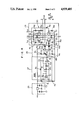
- the potential dividing point (connecting point) of resistor R 1 , R 2 is connected to a negative terminal of the comparator IC element IC 1 and the positive terminal of the comparator IC element IC 2 .
- the resistor R 4 is connected between the positive terminal of and the output terminal of the comparator IC element IC 1
- the resistor R 3 is connected between the positive terminal and the output terminal of the comparator IC element IC 2 .
- the square wave generating division of the oscillating circuit 27 is operated with the voltage of capacitor Cx, thereby the square wave voltage is output from the output terminal of IC element IC 1 , the square wave voltage is input to the triangular wave generating division circuit so that triangular wave voltages are integrated, and the triangular wave voltage V ⁇ is output from the output terminal of the IC element IC 2 .
- the collector of the npn transistor Tr 1 on one of the opposing lines is connected to the collector of the other pnp transistor Tr 4
- the collector of the npn transistor Tr 3 of one line of another opposing two lines is connected to the collector of the other pnp transistor Tr 2 .
- the comparator IC element IC 4 functionsve to produce signal Vd 2 which is sent to the earth through the diode D 2 , the resistor R 7 , and R 13 .
- the npn transistor Tr 3 is changed to an on-state, thereby electric current is sent from the voltage terminal V 2 to the earth through the resistors R 12 , and R 10 , and the collector and the emitter of npn transistor Tr 3 .
- the pnp transistor Tr 4 is changed to an on-state by the voltage on the resistor R 12 . Thereby, negative pulse voltage-Vp can be obtained at the output terminals 0 connected to the collector of the pnp transistor Tr 4 .
- the positive and negative pulse voltage ⁇ Vp can be freely changed by changing the DC voltage V 1 .
- the output terminal to the piezo-electric vibrator pump as shown in FIGS. 1 to 3
- the invertor can be simple and smaller and of low-cost construction as a switching element with a gate is not used;
- on-off states of the npn transistors and pnp transistors Tr 1 , Tr 2 , Tr 3 , and Tr 4 can be positively switched on and off even if the frequency and switching speed becomes higher with the two output operation signals Vd 1 , Vd 2 with the pulse quiescent period t 1 of the driving circuit 28 to which the output triangular wave voltage V ⁇ of the triangular wave oscilation circuit 27 is input and from which two operation signal Vd 1 , Vd 2 whose operating points are different from each other are output after the quiescent period t 1 .
Abstract
Description
______________________________________
       Self-suction
                 Pressure
       ability(mm)
                 (kg/cm)     Flow (ml/min)
       liquid
             gas     liquid  gas   liquid
                                         gas
______________________________________
Comparison
          50     --      0.05  0.02   80    500
Example  900     --      0.20  0.11  400   1000
______________________________________
Claims (9)
Applications Claiming Priority (2)
| Application Number | Priority Date | Filing Date | Title |
|---|---|---|---|
| JP62332600A JPH01174278A (en) | 1987-12-28 | 1987-12-28 | Inverter |
| JP62-332600 | 1987-12-28 |
Publications (1)
| Publication Number | Publication Date |
|---|---|
| US4939405A true US4939405A (en) | 1990-07-03 |
Family
ID=18256758
Family Applications (1)
| Application Number | Title | Priority Date | Filing Date |
|---|---|---|---|
| US07/289,625 Expired - Lifetime US4939405A (en) | 1987-12-28 | 1988-12-23 | Piezo-electric vibrator pump |
Country Status (4)
| Country | Link |
|---|---|
| US (1) | US4939405A (en) |
| EP (1) | EP0322899B1 (en) |
| JP (1) | JPH01174278A (en) |
| DE (1) | DE3881668T2 (en) |
Cited By (138)
| Publication number | Priority date | Publication date | Assignee | Title |
|---|---|---|---|---|
| US5171132A (en) * | 1989-12-27 | 1992-12-15 | Seiko Epson Corporation | Two-valve thin plate micropump |
| US5192197A (en) * | 1991-11-27 | 1993-03-09 | Rockwell International Corporation | Piezoelectric pump |
| US5197041A (en) * | 1991-01-23 | 1993-03-23 | Balogh William T | Piezoelectric mud pulser for measurement-while-drilling applications |
| US5219278A (en) * | 1989-11-10 | 1993-06-15 | Westonbridge International, Ltd. | Micropump with improved priming |
| US5338164A (en) * | 1993-05-28 | 1994-08-16 | Rockwell International Corporation | Positive displacement micropump |
| US5355048A (en) * | 1993-07-21 | 1994-10-11 | Fsi International, Inc. | Megasonic transducer for cleaning substrate surfaces |
| US5529465A (en) * | 1991-09-11 | 1996-06-25 | Fraunhofer-Gesellschaft Zur Forderung Der Angewandten Forschung E.V. | Micro-miniaturized, electrostatically driven diaphragm micropump |
| US5630709A (en) * | 1996-02-09 | 1997-05-20 | California Institute Of Technology | Pump having pistons and valves made of electroactive actuators |
| US5681152A (en) * | 1993-04-08 | 1997-10-28 | Sem, Ab | Membrane type fluid pump |
| US5761782A (en) * | 1994-08-29 | 1998-06-09 | Oceaneering International, Inc. | Method of fabrication of piezoelectric bender elements |
| US5769608A (en) * | 1994-06-10 | 1998-06-23 | P.D. Coop, Inc. | Resonant system to pump liquids, measure volume, and detect bubbles |
| US5798600A (en) * | 1994-08-29 | 1998-08-25 | Oceaneering International, Inc. | Piezoelectric pumps |
| US5852589A (en) * | 1990-07-19 | 1998-12-22 | Raytheon Company | Low cost composite transducer |
| US5889354A (en) * | 1994-08-29 | 1999-03-30 | Oceaneering International Inc. | Piezoelectric unit cell |
| US5896000A (en) * | 1996-02-09 | 1999-04-20 | Vectron Laboratories, Inc. | Mounting for reducing vibration-induced side bands |
| US6071087A (en) * | 1996-04-03 | 2000-06-06 | The United States Of America As Represented By The Administrator Of The National Aeronautics And Space Administration | Ferroelectric pump |
| WO2000036302A1 (en) | 1998-12-11 | 2000-06-22 | The United States Government As Represented By Theadministrator Of The National Aeronautics And Space Administration (Nasa) | Ferroelectric pump |
| US6118207A (en) * | 1997-11-12 | 2000-09-12 | Deka Products Limited Partnership | Piezo-electric actuator operable in an electrolytic fluid |
| US6215221B1 (en) * | 1998-12-29 | 2001-04-10 | Honeywell International Inc. | Electrostatic/pneumatic actuators for active surfaces |
| US6262519B1 (en) * | 1998-06-19 | 2001-07-17 | Eastman Kodak Company | Method of controlling fluid flow in a microfluidic process |
| US6291930B1 (en) | 1998-08-13 | 2001-09-18 | Oceaneering International, Inc. | Low voltage piezoelectric bender elements and unit cells |
| US6293255B1 (en) | 1997-01-31 | 2001-09-25 | Yamaha Hatsudoki Kabushiki Kaisha | Fuel injection system |
| US6344706B1 (en) * | 1998-10-20 | 2002-02-05 | Murata Manufacturing Co., Ltd | Piezoelectric component and method of manufacturing same |
| WO2002022358A1 (en) * | 2000-09-18 | 2002-03-21 | Par Technologies, Llc. | Piezoelectric actuator and pump using same |
| US6361284B2 (en) | 1996-02-12 | 2002-03-26 | Jean-Baptiste Drevet | Vibrating membrane fluid circulator |
| US6392331B1 (en) * | 1998-12-24 | 2002-05-21 | Abb Ricerca Spa | Bistable actuator |
| US20030002995A1 (en) * | 2001-04-24 | 2003-01-02 | Matsushita Electric Works, Ltd. | Pump and method of manufacturing same |
| US6568052B1 (en) * | 1999-04-16 | 2003-05-27 | The United States Of America As Represented By The Secretary Of The Navy | Method for constructing a fluidic driver for use with microfluidic circuits as a pump and mixer |
| US6568286B1 (en) | 2000-06-02 | 2003-05-27 | Honeywell International Inc. | 3D array of integrated cells for the sampling and detection of air bound chemical and biological species |
| US20030107302A1 (en) * | 2001-07-27 | 2003-06-12 | Michael Birth | Piezoelectric element and an oscillation transducer with a piezoelectric element |
| US6589229B1 (en) | 2000-07-31 | 2003-07-08 | Becton, Dickinson And Company | Wearable, self-contained drug infusion device |
| US6604915B1 (en) * | 2002-03-20 | 2003-08-12 | Csa Engineering, Inc. | Compact, high efficiency, smart material actuated hydraulic pump |
| EP1354706A1 (en) * | 2002-04-15 | 2003-10-22 | Eastman Kodak Company | Drop-on-demand liquid emission using interconnected dual electrodes as ejection device |
| US6653762B2 (en) * | 2000-04-19 | 2003-11-25 | Murata Manufacturing Co., Ltd. | Piezoelectric type electric acoustic converter |
| US6659740B2 (en) | 1998-08-11 | 2003-12-09 | Jean-Baptiste Drevet | Vibrating membrane fluid circulator |
| US20040000843A1 (en) * | 2000-09-18 | 2004-01-01 | East W. Joe | Piezoelectric actuator and pump using same |
| US20040001767A1 (en) * | 2002-07-01 | 2004-01-01 | Peters Richard D. | Piezoelectric micropump with diaphragm and valves |
| US6729856B2 (en) | 2001-10-09 | 2004-05-04 | Honeywell International Inc. | Electrostatically actuated pump with elastic restoring forces |
| US6781285B1 (en) * | 1994-01-27 | 2004-08-24 | Cymer, Inc. | Packaged strain actuator |
| US20040211077A1 (en) * | 2002-08-21 | 2004-10-28 | Honeywell International Inc. | Method and apparatus for receiving a removable media member |
| US6837476B2 (en) | 2002-06-19 | 2005-01-04 | Honeywell International Inc. | Electrostatically actuated valve |
| US20050074662A1 (en) * | 2003-10-07 | 2005-04-07 | Samsung Electronics Co., Ltd. | Valveless micro air delivery device |
| US20050139002A1 (en) * | 2003-12-26 | 2005-06-30 | Alps Electric Co., Ltd. | Pump actuated by diaphragm |
| US20050219288A1 (en) * | 2004-04-02 | 2005-10-06 | Jim Vogeley | Piezoelectric devices and methods and circuits for driving same |
| US20050219302A1 (en) * | 2004-04-02 | 2005-10-06 | Par Technologies, Llc | Piezoelectric devices and methods and circuits for driving same |
| US20050225201A1 (en) * | 2004-04-02 | 2005-10-13 | Par Technologies, Llc | Piezoelectric devices and methods and circuits for driving same |
| US20050225202A1 (en) * | 2004-04-02 | 2005-10-13 | James Vogeley | Piezoelectric devices and methods and circuits for driving same |
| US20050233197A1 (en) * | 2004-02-27 | 2005-10-20 | Norikazu Nakayama | Fuel-cell device, gas-injecting unit, and method for generating power using the fuel-cell device |
| US20060134510A1 (en) * | 2004-12-21 | 2006-06-22 | Cleopatra Cabuz | Air cell air flow control system and method |
| US20060137749A1 (en) * | 2004-12-29 | 2006-06-29 | Ulrich Bonne | Electrostatically actuated gas valve |
| US20060138903A1 (en) * | 2004-12-23 | 2006-06-29 | Askew Andy R | Piezoelectric bimorph actuator and method of manufacturing thereof |
| US20060145110A1 (en) * | 2005-01-06 | 2006-07-06 | Tzu-Yu Wang | Microfluidic modulating valve |
| US20060146096A1 (en) * | 2004-12-30 | 2006-07-06 | Par Technologies, Llc | Actuators with diaphragm and methods of operating same |
| US20060147329A1 (en) * | 2004-12-30 | 2006-07-06 | Tanner Edward T | Active valve and active valving for pump |
| US20060147324A1 (en) * | 2004-12-30 | 2006-07-06 | Par Technologies | Method and apparatus for scavenging energy during pump operation |
| US20060159568A1 (en) * | 2003-06-30 | 2006-07-20 | Koninklijke Philips Electronics N.V. | Device for generating a medium stream |
| US20060165836A1 (en) * | 2002-11-14 | 2006-07-27 | Vollrath Friedrich Wilhelm L P | Apparatus and method for forming materials |
| US20060169326A1 (en) * | 2005-01-28 | 2006-08-03 | Honyewll International Inc. | Mesovalve modulator |
| US20060185822A1 (en) * | 2004-07-07 | 2006-08-24 | Georgia Tech Research Corporation | System and method for thermal management using distributed synthetic jet actuators |
| US20060232166A1 (en) * | 2005-04-13 | 2006-10-19 | Par Technologies Llc | Stacked piezoelectric diaphragm members |
| US20060232171A1 (en) * | 2005-04-13 | 2006-10-19 | Par Technologies, Llc | Piezoelectric diaphragm assembly with conductors on flexible film |
| US20060245950A1 (en) * | 2004-12-30 | 2006-11-02 | Par Technologies, Llc | Actuators with connected diaphragms |
| US20060269427A1 (en) * | 2005-05-26 | 2006-11-30 | Drummond Robert E Jr | Miniaturized diaphragm pump with non-resilient seals |
| US20060272718A1 (en) * | 2005-06-03 | 2006-12-07 | Honeywell International Inc. | Microvalve package assembly |
| US20070014676A1 (en) * | 2005-07-14 | 2007-01-18 | Honeywell International Inc. | Asymmetric dual diaphragm pump |
| US20070023169A1 (en) * | 2005-07-29 | 2007-02-01 | Innovative Fluidics, Inc. | Synthetic jet ejector for augmentation of pumped liquid loop cooling and enhancement of pool and flow boiling |
| US20070051415A1 (en) * | 2005-09-07 | 2007-03-08 | Honeywell International Inc. | Microvalve switching array |
| US20070075286A1 (en) * | 2005-10-04 | 2007-04-05 | Par Technologies, Llc | Piezoelectric valves drive |
| US20070096118A1 (en) * | 2005-11-02 | 2007-05-03 | Innovative Fluidics, Inc. | Synthetic jet cooling system for LED module |
| US20070119575A1 (en) * | 2005-11-14 | 2007-05-31 | Innovative Fluidics, Inc. | Synthetic jet heat pipe thermal management system |
| US20070129681A1 (en) * | 2005-11-01 | 2007-06-07 | Par Technologies, Llc | Piezoelectric actuation of piston within dispensing chamber |
| US20070128055A1 (en) * | 2004-07-19 | 2007-06-07 | Lee J K | Diaphragm pump for medical applications |
| US20070131286A1 (en) * | 2005-12-09 | 2007-06-14 | Honeywell International Inc. | Gas valve with overtravel |
| US20070138914A1 (en) * | 2005-12-15 | 2007-06-21 | Alps Electric Co., Ltd. | Wiring structure of vibrator, and piezoelectric pump |
| US20070145861A1 (en) * | 2005-11-18 | 2007-06-28 | Par Technologies, Llc | Human powered piezoelectric power generating device |
| US20070221276A1 (en) * | 2006-03-22 | 2007-09-27 | Honeywell International Inc. | Modulating gas valves and systems |
| US20070295480A1 (en) * | 2006-06-26 | 2007-12-27 | International Business Machines Corporation | Multi-fluid cooling system, cooled electronics module, and methods of fabrication thereof |
| US20080029207A1 (en) * | 2006-07-20 | 2008-02-07 | Smith Timothy J | Insert Molded Actuator Components |
| US20080099082A1 (en) * | 2006-10-27 | 2008-05-01 | Honeywell International Inc. | Gas valve shutoff seal |
| US20080128037A1 (en) * | 2006-11-30 | 2008-06-05 | Honeywell International Inc. | Gas valve with resilient seat |
| US20080170951A1 (en) * | 2007-01-17 | 2008-07-17 | Alps Electric Co., Ltd. | Piezoelectric pump |
| US7420659B1 (en) | 2000-06-02 | 2008-09-02 | Honeywell Interantional Inc. | Flow control system of a cartridge |
| US20080246367A1 (en) * | 2006-12-29 | 2008-10-09 | Adaptivenergy, Llc | Tuned laminated piezoelectric elements and methods of tuning same |
| CN100430599C (en) * | 2003-06-30 | 2008-11-05 | Nxp股份有限公司 | Device for generating a medium stream |
| US20080304983A1 (en) * | 2007-06-08 | 2008-12-11 | Satoshi Yamada | Diaphragm air pump |
| US20090148318A1 (en) * | 2006-12-09 | 2009-06-11 | Murata Manufacturing Co., Ltd. | Piezoelectric Pump |
| US20090174999A1 (en) * | 2007-09-27 | 2009-07-09 | Ioan Sauciuc | Piezoelectric air jet augmented cooling for electronic devices |
| US20090196778A1 (en) * | 2004-12-22 | 2009-08-06 | Matsushita Electric Works, Ltd. | Liquid discharge control apparatus |
| US20090214362A1 (en) * | 2007-12-03 | 2009-08-27 | Murata Manufacturing Co., Ltd. | Piezoelectric pump |
| US20090297372A1 (en) * | 2005-09-09 | 2009-12-03 | Board Of Trustees Of The University Of Illinois | Dual Chamber Valveless Mems Micropump |
| US7629728B1 (en) | 2008-07-15 | 2009-12-08 | Iptrade, Inc. | Scalable piezoelectric package |
| US20100013352A1 (en) * | 2008-07-15 | 2010-01-21 | Baruch Pletner | Unimorph/bimorph piezoelectric package |
| US20100021322A1 (en) * | 2006-07-25 | 2010-01-28 | Panasonic Electric Works Co., Ltd. | Diaphragm pump |
| US20100068080A1 (en) * | 2008-09-15 | 2010-03-18 | Microbase Technology Corp. | Wiring structure for use in micro piezoelectric pump |
| US7721716B1 (en) * | 2008-07-16 | 2010-05-25 | Harwood Michael R | High pressure piezoelectric fuel injector |
| US20100296248A1 (en) * | 2006-06-26 | 2010-11-25 | International Business Machines Corporation | Dual-chamber fluid pump for a multi-fluid electronics cooling system and method |
| US20110018391A1 (en) * | 2008-03-28 | 2011-01-27 | Franck Mandica | Domestic applicance comprising a piezoelectric pump provided with a simplified power supply circuit |
| US8030886B2 (en) | 2005-12-21 | 2011-10-04 | Nuventix, Inc. | Thermal management of batteries using synthetic jets |
| US20120069305A1 (en) * | 2010-09-21 | 2012-03-22 | Seiko Epson Corporation | Cooling device and projector |
| US20120171062A1 (en) * | 2010-05-21 | 2012-07-05 | Murata Manufacturing Co., Ltd. | Fluid pump |
| US20130020403A1 (en) * | 2011-07-21 | 2013-01-24 | Lockheed Martin Corporation | Synthetic Jet Apparatus |
| US8485793B1 (en) * | 2007-09-14 | 2013-07-16 | Aprolase Development Co., Llc | Chip scale vacuum pump |
| US20130272902A1 (en) * | 2010-12-23 | 2013-10-17 | Debiotech S.A. | Electronic control method and system for a piezo-electric pump |
| US8839815B2 (en) | 2011-12-15 | 2014-09-23 | Honeywell International Inc. | Gas valve with electronic cycle counter |
| US8899264B2 (en) | 2011-12-15 | 2014-12-02 | Honeywell International Inc. | Gas valve with electronic proof of closure system |
| US8905063B2 (en) | 2011-12-15 | 2014-12-09 | Honeywell International Inc. | Gas valve with fuel rate monitor |
| US8947242B2 (en) | 2011-12-15 | 2015-02-03 | Honeywell International Inc. | Gas valve with valve leakage test |
| US9074770B2 (en) | 2011-12-15 | 2015-07-07 | Honeywell International Inc. | Gas valve with electronic valve proving system |
| US20150308602A1 (en) * | 2014-04-24 | 2015-10-29 | Hydac Technology Gmbh | Damping device |
| US9234661B2 (en) | 2012-09-15 | 2016-01-12 | Honeywell International Inc. | Burner control system |
| US9284930B2 (en) | 2011-06-03 | 2016-03-15 | Michael R. Harwood | High pressure piezoelectric fuel injector |
| US20160266085A1 (en) * | 2013-11-20 | 2016-09-15 | Maschinenfabrik Reinhausen Gmbh | Apparatus and method for detecting gas |
| US9557059B2 (en) | 2011-12-15 | 2017-01-31 | Honeywell International Inc | Gas valve with communication link |
| US9645584B2 (en) | 2014-09-17 | 2017-05-09 | Honeywell International Inc. | Gas valve with electronic health monitoring |
| US9683674B2 (en) | 2013-10-29 | 2017-06-20 | Honeywell Technologies Sarl | Regulating device |
| US20170279029A1 (en) * | 2016-03-22 | 2017-09-28 | Seiko Epson Corporation | Control circuit of piezoelectric driving device, piezoelectric driving device, ultrasonic motor, robot, hand, and pump |
| US9835265B2 (en) | 2011-12-15 | 2017-12-05 | Honeywell International Inc. | Valve with actuator diagnostics |
| US9841122B2 (en) | 2014-09-09 | 2017-12-12 | Honeywell International Inc. | Gas valve with electronic valve proving system |
| US9846440B2 (en) | 2011-12-15 | 2017-12-19 | Honeywell International Inc. | Valve controller configured to estimate fuel comsumption |
| US9851103B2 (en) | 2011-12-15 | 2017-12-26 | Honeywell International Inc. | Gas valve with overpressure diagnostics |
| US9968720B2 (en) | 2016-04-11 | 2018-05-15 | CorWave SA | Implantable pump system having an undulating membrane |
| US9995486B2 (en) | 2011-12-15 | 2018-06-12 | Honeywell International Inc. | Gas valve with high/low gas pressure detection |
| US10024439B2 (en) | 2013-12-16 | 2018-07-17 | Honeywell International Inc. | Valve over-travel mechanism |
| US10166319B2 (en) | 2016-04-11 | 2019-01-01 | CorWave SA | Implantable pump system having a coaxial ventricular cannula |
| US10188779B1 (en) | 2017-11-29 | 2019-01-29 | CorWave SA | Implantable pump system having an undulating membrane with improved hydraulic performance |
| US10422531B2 (en) | 2012-09-15 | 2019-09-24 | Honeywell International Inc. | System and approach for controlling a combustion chamber |
| US10503181B2 (en) | 2016-01-13 | 2019-12-10 | Honeywell International Inc. | Pressure regulator |
| US10564062B2 (en) | 2016-10-19 | 2020-02-18 | Honeywell International Inc. | Human-machine interface for gas valve |
| US10619631B2 (en) * | 2017-01-05 | 2020-04-14 | Microjet Technology Co., Ltd. | Miniature pneumatic device |
| US10697815B2 (en) | 2018-06-09 | 2020-06-30 | Honeywell International Inc. | System and methods for mitigating condensation in a sensor module |
| US10799625B2 (en) | 2019-03-15 | 2020-10-13 | CorWave SA | Systems and methods for controlling an implantable blood pump |
| US10933181B2 (en) | 2017-03-31 | 2021-03-02 | CorWave SA | Implantable pump system having a rectangular membrane |
| US11073281B2 (en) | 2017-12-29 | 2021-07-27 | Honeywell International Inc. | Closed-loop programming and control of a combustion appliance |
| US11191946B2 (en) | 2020-03-06 | 2021-12-07 | CorWave SA | Implantable blood pumps comprising a linear bearing |
| CN113944615A (en) * | 2021-10-26 | 2022-01-18 | 上海应用技术大学 | Integrated micro-piezoelectric liquid pumping device and manufacturing and driving method thereof |
| US20220034310A1 (en) * | 2020-07-30 | 2022-02-03 | Festo Se & Co. Kg | Fluid device |
| US11508901B2 (en) | 2017-11-09 | 2022-11-22 | Murata Manufacturing Co., Ltd. | Piezoelectric component, sensor, and actuator |
| US11512689B2 (en) | 2017-11-10 | 2022-11-29 | CorWave SA | Undulating-membrane fluid circulator |
Families Citing this family (18)
| Publication number | Priority date | Publication date | Assignee | Title |
|---|---|---|---|---|
| KR910008284A (en) * | 1989-10-17 | 1991-05-31 | 야마무라 가쯔미 | Micro pump |
| US5466932A (en) * | 1993-09-22 | 1995-11-14 | Westinghouse Electric Corp. | Micro-miniature piezoelectric diaphragm pump for the low pressure pumping of gases |
| DE10232692A1 (en) * | 2002-07-18 | 2004-02-12 | Siemens Ag | Cooling system for an electronic device has fluid circulated around a cooling loop by a piezo electric oscillated diaphragm pumping unit |
| WO2005026544A1 (en) * | 2003-08-05 | 2005-03-24 | David Deak | Piezoelectric pump |
| DE10345694A1 (en) * | 2003-10-01 | 2005-04-21 | Korfmacher Georg | Method and device for conveying media |
| DE102004016764B3 (en) * | 2004-04-01 | 2005-09-08 | Honeywell B.V. | Fail-safe circuit for gas valve, especially piezo-driven gas valve, uses fail-safe circuit for providing output voltage to open gas valve |
| DE102006016571B4 (en) * | 2006-04-06 | 2008-09-04 | Bartels Mikrotechnik Gmbh | Method and device for the automated conveyance of liquids or gases |
| US8432057B2 (en) | 2007-05-01 | 2013-04-30 | Pliant Energy Systems Llc | Pliant or compliant elements for harnessing the forces of moving fluid to transport fluid or generate electricity |
| US9145875B2 (en) | 2007-05-01 | 2015-09-29 | Pliant Energy Systems Llc | Ribbon transducer and pump apparatuses, methods and systems |
| US8643253B1 (en) * | 2007-09-03 | 2014-02-04 | Joseph Anthony Micallef | Piezoelectric ultracapacitors |
| BR112012001556A2 (en) * | 2009-07-21 | 2021-01-12 | Pliant Energy Systems Llc | energy generator, mechanism for extracting energy from a directional flow of a fluid, energy extraction apparatus and system, and methods for extracting energy from a flow fluid, and for forming an apparatus for extracting energy. |
| WO2012097005A1 (en) | 2011-01-10 | 2012-07-19 | Benjamin Pietro Filardo | Mechanisms for creating undulating motion. such as for propulsion. and for harnessing the energy of moving fluid |
| US9752990B2 (en) | 2013-09-30 | 2017-09-05 | Honeywell International Inc. | Low-powered system for driving a fuel control mechanism |
| US10190570B1 (en) | 2016-06-30 | 2019-01-29 | Pliant Energy Systems Llc | Traveling wave propeller, pump and generator apparatuses, methods and systems |
| US11795900B2 (en) | 2016-06-30 | 2023-10-24 | Pliant Energy Systems Llc | Vehicle with traveling wave thrust module apparatuses, methods and systems |
| US11209022B2 (en) | 2016-06-30 | 2021-12-28 | Pliant Energy Systems Llc | Vehicle with traveling wave thrust module apparatuses, methods and systems |
| US10519926B2 (en) | 2016-06-30 | 2019-12-31 | Pliant Energy Systems Llc | Traveling wave propeller, pump and generator apparatuses, methods and systems |
| CN107939658B (en) * | 2016-10-13 | 2019-11-05 | 研能科技股份有限公司 | The drive system of piezoelectric pump |
Citations (5)
| Publication number | Priority date | Publication date | Assignee | Title |
|---|---|---|---|---|
| US3270672A (en) * | 1963-12-23 | 1966-09-06 | Union Oil Co | Pump apparatus |
| US3361067A (en) * | 1966-09-09 | 1968-01-02 | Nasa Usa | Piezoelectric pump |
| US4140936A (en) * | 1977-09-01 | 1979-02-20 | The United States Of America As Represented By The Secretary Of The Navy | Square and rectangular electroacoustic bender bar transducer |
| US4492360A (en) * | 1982-06-07 | 1985-01-08 | The Lee Company | Piezoelectric valve |
| US4708600A (en) * | 1986-02-24 | 1987-11-24 | Abujudom Ii David N | Piezoelectric fluid pumping apparatus |
Family Cites Families (8)
| Publication number | Priority date | Publication date | Assignee | Title |
|---|---|---|---|---|
| US3255779A (en) * | 1960-07-27 | 1966-06-14 | Peters & Russell Inc | Surge chamber |
| US3657930A (en) * | 1969-06-24 | 1972-04-25 | Bendix Corp | Piezoelectric crystal operated pump to supply fluid pressure to hydrostatically support inner bearings of a gyroscope |
| US3606592A (en) * | 1970-05-20 | 1971-09-20 | Bendix Corp | Fluid pump |
| US4011474A (en) * | 1974-10-03 | 1977-03-08 | Pz Technology, Inc. | Piezoelectric stack insulation |
| FR2425555A1 (en) * | 1978-05-08 | 1979-12-07 | Pn Sas Negro Et Co | Membrane fuel pump for IC engine - has inlet and discharge chambers forming air pockets to reduce pressure fluctuations |
| JPS5613719U (en) * | 1979-07-13 | 1981-02-05 | ||
| IT8222121V0 (en) * | 1982-06-08 | 1982-06-08 | Siette Spa | DIAPHRAGM PUMP, ESPECIALLY FOR FUEL SUPPLY TO AN INTERNAL COMBUSTION ENGINE. |
| JPS60159387A (en) * | 1984-01-30 | 1985-08-20 | Sharp Corp | Pump |
-
1987
- 1987-12-28 JP JP62332600A patent/JPH01174278A/en active Pending
-
1988
- 1988-12-23 US US07/289,625 patent/US4939405A/en not_active Expired - Lifetime
- 1988-12-28 EP EP88121803A patent/EP0322899B1/en not_active Expired - Lifetime
- 1988-12-28 DE DE8888121803T patent/DE3881668T2/en not_active Expired - Fee Related
Patent Citations (5)
| Publication number | Priority date | Publication date | Assignee | Title |
|---|---|---|---|---|
| US3270672A (en) * | 1963-12-23 | 1966-09-06 | Union Oil Co | Pump apparatus |
| US3361067A (en) * | 1966-09-09 | 1968-01-02 | Nasa Usa | Piezoelectric pump |
| US4140936A (en) * | 1977-09-01 | 1979-02-20 | The United States Of America As Represented By The Secretary Of The Navy | Square and rectangular electroacoustic bender bar transducer |
| US4492360A (en) * | 1982-06-07 | 1985-01-08 | The Lee Company | Piezoelectric valve |
| US4708600A (en) * | 1986-02-24 | 1987-11-24 | Abujudom Ii David N | Piezoelectric fluid pumping apparatus |
Cited By (223)
| Publication number | Priority date | Publication date | Assignee | Title |
|---|---|---|---|---|
| US5219278A (en) * | 1989-11-10 | 1993-06-15 | Westonbridge International, Ltd. | Micropump with improved priming |
| US5171132A (en) * | 1989-12-27 | 1992-12-15 | Seiko Epson Corporation | Two-valve thin plate micropump |
| US5852589A (en) * | 1990-07-19 | 1998-12-22 | Raytheon Company | Low cost composite transducer |
| US5197041A (en) * | 1991-01-23 | 1993-03-23 | Balogh William T | Piezoelectric mud pulser for measurement-while-drilling applications |
| US5529465A (en) * | 1991-09-11 | 1996-06-25 | Fraunhofer-Gesellschaft Zur Forderung Der Angewandten Forschung E.V. | Micro-miniaturized, electrostatically driven diaphragm micropump |
| US5192197A (en) * | 1991-11-27 | 1993-03-09 | Rockwell International Corporation | Piezoelectric pump |
| US5681152A (en) * | 1993-04-08 | 1997-10-28 | Sem, Ab | Membrane type fluid pump |
| US5338164A (en) * | 1993-05-28 | 1994-08-16 | Rockwell International Corporation | Positive displacement micropump |
| US5355048A (en) * | 1993-07-21 | 1994-10-11 | Fsi International, Inc. | Megasonic transducer for cleaning substrate surfaces |
| US6781285B1 (en) * | 1994-01-27 | 2004-08-24 | Cymer, Inc. | Packaged strain actuator |
| US5769608A (en) * | 1994-06-10 | 1998-06-23 | P.D. Coop, Inc. | Resonant system to pump liquids, measure volume, and detect bubbles |
| US5889354A (en) * | 1994-08-29 | 1999-03-30 | Oceaneering International Inc. | Piezoelectric unit cell |
| US5798600A (en) * | 1994-08-29 | 1998-08-25 | Oceaneering International, Inc. | Piezoelectric pumps |
| US5761782A (en) * | 1994-08-29 | 1998-06-09 | Oceaneering International, Inc. | Method of fabrication of piezoelectric bender elements |
| US5896000A (en) * | 1996-02-09 | 1999-04-20 | Vectron Laboratories, Inc. | Mounting for reducing vibration-induced side bands |
| US5630709A (en) * | 1996-02-09 | 1997-05-20 | California Institute Of Technology | Pump having pistons and valves made of electroactive actuators |
| US6361284B2 (en) | 1996-02-12 | 2002-03-26 | Jean-Baptiste Drevet | Vibrating membrane fluid circulator |
| US6071087A (en) * | 1996-04-03 | 2000-06-06 | The United States Of America As Represented By The Administrator Of The National Aeronautics And Space Administration | Ferroelectric pump |
| US6293255B1 (en) | 1997-01-31 | 2001-09-25 | Yamaha Hatsudoki Kabushiki Kaisha | Fuel injection system |
| US6118207A (en) * | 1997-11-12 | 2000-09-12 | Deka Products Limited Partnership | Piezo-electric actuator operable in an electrolytic fluid |
| US6316864B1 (en) | 1997-11-12 | 2001-11-13 | Deka Products Limited Partnership | Piezo-electric actuator operable in an electrolytic fluid |
| US6262519B1 (en) * | 1998-06-19 | 2001-07-17 | Eastman Kodak Company | Method of controlling fluid flow in a microfluidic process |
| US6659740B2 (en) | 1998-08-11 | 2003-12-09 | Jean-Baptiste Drevet | Vibrating membrane fluid circulator |
| US6291930B1 (en) | 1998-08-13 | 2001-09-18 | Oceaneering International, Inc. | Low voltage piezoelectric bender elements and unit cells |
| US6344706B1 (en) * | 1998-10-20 | 2002-02-05 | Murata Manufacturing Co., Ltd | Piezoelectric component and method of manufacturing same |
| WO2000036302A1 (en) | 1998-12-11 | 2000-06-22 | The United States Government As Represented By Theadministrator Of The National Aeronautics And Space Administration (Nasa) | Ferroelectric pump |
| US6392331B1 (en) * | 1998-12-24 | 2002-05-21 | Abb Ricerca Spa | Bistable actuator |
| US6215221B1 (en) * | 1998-12-29 | 2001-04-10 | Honeywell International Inc. | Electrostatic/pneumatic actuators for active surfaces |
| US6568052B1 (en) * | 1999-04-16 | 2003-05-27 | The United States Of America As Represented By The Secretary Of The Navy | Method for constructing a fluidic driver for use with microfluidic circuits as a pump and mixer |
| US7103949B2 (en) * | 1999-04-16 | 2006-09-12 | The United States Of America As Represented By The Secretary Of The Navy | Method for fabricating a transducer |
| US20040042915A1 (en) * | 1999-04-16 | 2004-03-04 | Rife Jack C. | Fluidic drive for miniature acoustic fluidic pumps and mixers |
| US6825593B2 (en) | 2000-04-19 | 2004-11-30 | Murata Manufacturing Co., Ltd. | Piezoelectric type electric acoustic converter |
| US6653762B2 (en) * | 2000-04-19 | 2003-11-25 | Murata Manufacturing Co., Ltd. | Piezoelectric type electric acoustic converter |
| US6568286B1 (en) | 2000-06-02 | 2003-05-27 | Honeywell International Inc. | 3D array of integrated cells for the sampling and detection of air bound chemical and biological species |
| US7420659B1 (en) | 2000-06-02 | 2008-09-02 | Honeywell Interantional Inc. | Flow control system of a cartridge |
| US6889567B2 (en) | 2000-06-02 | 2005-05-10 | Honeywell International Inc. | 3D array integrated cells for the sampling and detection of air bound chemical and biological species |
| US6758107B2 (en) | 2000-06-02 | 2004-07-06 | Honeywell International Inc. | 3D array of integrated cells for the sampling and detection of air bound chemical and biological species |
| US6589229B1 (en) | 2000-07-31 | 2003-07-08 | Becton, Dickinson And Company | Wearable, self-contained drug infusion device |
| US20040000843A1 (en) * | 2000-09-18 | 2004-01-01 | East W. Joe | Piezoelectric actuator and pump using same |
| US20040021398A1 (en) * | 2000-09-18 | 2004-02-05 | East W. Joe | Piezoelectric actuator and pump using same |
| US7191503B2 (en) | 2000-09-18 | 2007-03-20 | Par Technologies, Llc | Method of manufacturing a piezoelectric actuator |
| WO2002022358A1 (en) * | 2000-09-18 | 2002-03-21 | Par Technologies, Llc. | Piezoelectric actuator and pump using same |
| GB2387965A (en) * | 2000-09-18 | 2003-10-29 | Par Technologies Llc | Piezoelectric actuator and pump using same |
| US7198250B2 (en) | 2000-09-18 | 2007-04-03 | Par Technologies, Llc | Piezoelectric actuator and pump using same |
| US20060056999A1 (en) * | 2000-09-18 | 2006-03-16 | Par Technologies Llc | Piezoelectric actuator and pump using same |
| GB2387965B (en) * | 2000-09-18 | 2005-05-18 | Par Technologies Llc | Piezoelectric actuator and pump using same |
| US20030002995A1 (en) * | 2001-04-24 | 2003-01-02 | Matsushita Electric Works, Ltd. | Pump and method of manufacturing same |
| US20030107302A1 (en) * | 2001-07-27 | 2003-06-12 | Michael Birth | Piezoelectric element and an oscillation transducer with a piezoelectric element |
| US6897601B2 (en) * | 2001-07-27 | 2005-05-24 | Holmberg Gmbh & Co. Kg | Piezoelectric element and an oscillation transducer with a piezoelectric element |
| US6729856B2 (en) | 2001-10-09 | 2004-05-04 | Honeywell International Inc. | Electrostatically actuated pump with elastic restoring forces |
| US6767190B2 (en) | 2001-10-09 | 2004-07-27 | Honeywell International Inc. | Methods of operating an electrostatically actuated pump |
| US6604915B1 (en) * | 2002-03-20 | 2003-08-12 | Csa Engineering, Inc. | Compact, high efficiency, smart material actuated hydraulic pump |
| EP1354706A1 (en) * | 2002-04-15 | 2003-10-22 | Eastman Kodak Company | Drop-on-demand liquid emission using interconnected dual electrodes as ejection device |
| US20050062001A1 (en) * | 2002-06-19 | 2005-03-24 | Cleopatra Cabuz | Electrostatically actuated valve |
| US6837476B2 (en) | 2002-06-19 | 2005-01-04 | Honeywell International Inc. | Electrostatically actuated valve |
| US6968862B2 (en) | 2002-06-19 | 2005-11-29 | Honeywell International Inc. | Electrostatically actuated valve |
| US6827559B2 (en) | 2002-07-01 | 2004-12-07 | Ventaira Pharmaceuticals, Inc. | Piezoelectric micropump with diaphragm and valves |
| US20040001767A1 (en) * | 2002-07-01 | 2004-01-01 | Peters Richard D. | Piezoelectric micropump with diaphragm and valves |
| US20040211077A1 (en) * | 2002-08-21 | 2004-10-28 | Honeywell International Inc. | Method and apparatus for receiving a removable media member |
| US7000330B2 (en) | 2002-08-21 | 2006-02-21 | Honeywell International Inc. | Method and apparatus for receiving a removable media member |
| US20060165836A1 (en) * | 2002-11-14 | 2006-07-27 | Vollrath Friedrich Wilhelm L P | Apparatus and method for forming materials |
| US7889877B2 (en) * | 2003-06-30 | 2011-02-15 | Nxp B.V. | Device for generating a medium stream |
| CN100430599C (en) * | 2003-06-30 | 2008-11-05 | Nxp股份有限公司 | Device for generating a medium stream |
| US20060159568A1 (en) * | 2003-06-30 | 2006-07-20 | Koninklijke Philips Electronics N.V. | Device for generating a medium stream |
| US7841843B2 (en) * | 2003-10-07 | 2010-11-30 | Samsung Electronics Co., Ltd. | Valveless micro air delivery device |
| US20050074662A1 (en) * | 2003-10-07 | 2005-04-07 | Samsung Electronics Co., Ltd. | Valveless micro air delivery device |
| US20050139002A1 (en) * | 2003-12-26 | 2005-06-30 | Alps Electric Co., Ltd. | Pump actuated by diaphragm |
| US7431574B2 (en) * | 2003-12-26 | 2008-10-07 | Alps Electric Co., Ltd. | Pump actuated by diaphragm |
| US20050233197A1 (en) * | 2004-02-27 | 2005-10-20 | Norikazu Nakayama | Fuel-cell device, gas-injecting unit, and method for generating power using the fuel-cell device |
| US20050219302A1 (en) * | 2004-04-02 | 2005-10-06 | Par Technologies, Llc | Piezoelectric devices and methods and circuits for driving same |
| US7312554B2 (en) * | 2004-04-02 | 2007-12-25 | Adaptivenergy, Llc | Piezoelectric devices and methods and circuits for driving same |
| WO2005098984A3 (en) * | 2004-04-02 | 2007-07-12 | Par Technologies Llc | Piezoelectric devices and methods and circuits for driving same |
| US20050219288A1 (en) * | 2004-04-02 | 2005-10-06 | Jim Vogeley | Piezoelectric devices and methods and circuits for driving same |
| US7287965B2 (en) * | 2004-04-02 | 2007-10-30 | Adaptiv Energy Llc | Piezoelectric devices and methods and circuits for driving same |
| WO2005097509A3 (en) * | 2004-04-02 | 2006-02-16 | Par Technologies Llc | Piezoelectric devices and methods and circuits for driving same |
| WO2005097509A2 (en) * | 2004-04-02 | 2005-10-20 | Par Technologies, Llc | Piezoelectric devices and methods and circuits for driving same |
| US20070216256A1 (en) * | 2004-04-02 | 2007-09-20 | Par Technologies, Llc | Piezoelectric devices and methods and circuits for driving same |
| US7290993B2 (en) * | 2004-04-02 | 2007-11-06 | Adaptivenergy Llc | Piezoelectric devices and methods and circuits for driving same |
| US7317274B2 (en) | 2004-04-02 | 2008-01-08 | Adaptivenergy, Llc. | Piezoelectric devices and methods and circuits for driving same |
| US20080018200A1 (en) * | 2004-04-02 | 2008-01-24 | Adaptivenergy, Llc | Piezoelectric devices and methods and circuits for driving same |
| US20050225201A1 (en) * | 2004-04-02 | 2005-10-13 | Par Technologies, Llc | Piezoelectric devices and methods and circuits for driving same |
| US20050225202A1 (en) * | 2004-04-02 | 2005-10-13 | James Vogeley | Piezoelectric devices and methods and circuits for driving same |
| US7969064B2 (en) | 2004-04-02 | 2011-06-28 | Par Technologies, Llc. | Piezoelectric devices and methods and circuits for driving same |
| WO2005098984A2 (en) * | 2004-04-02 | 2005-10-20 | Par Technologies, Llc. | Piezoelectric devices and methods and circuits for driving same |
| US20060185822A1 (en) * | 2004-07-07 | 2006-08-24 | Georgia Tech Research Corporation | System and method for thermal management using distributed synthetic jet actuators |
| US20070128055A1 (en) * | 2004-07-19 | 2007-06-07 | Lee J K | Diaphragm pump for medical applications |
| US20060134510A1 (en) * | 2004-12-21 | 2006-06-22 | Cleopatra Cabuz | Air cell air flow control system and method |
| US20090196778A1 (en) * | 2004-12-22 | 2009-08-06 | Matsushita Electric Works, Ltd. | Liquid discharge control apparatus |
| US7942650B2 (en) * | 2004-12-22 | 2011-05-17 | Panasonic Electric Works Co., Ltd. | Liquid discharge control apparatus including a pump and accumulator with a movable member |
| US20060138903A1 (en) * | 2004-12-23 | 2006-06-29 | Askew Andy R | Piezoelectric bimorph actuator and method of manufacturing thereof |
| US7259499B2 (en) | 2004-12-23 | 2007-08-21 | Askew Andy R | Piezoelectric bimorph actuator and method of manufacturing thereof |
| US7222639B2 (en) | 2004-12-29 | 2007-05-29 | Honeywell International Inc. | Electrostatically actuated gas valve |
| US20060137749A1 (en) * | 2004-12-29 | 2006-06-29 | Ulrich Bonne | Electrostatically actuated gas valve |
| US20060245950A1 (en) * | 2004-12-30 | 2006-11-02 | Par Technologies, Llc | Actuators with connected diaphragms |
| US20060147324A1 (en) * | 2004-12-30 | 2006-07-06 | Par Technologies | Method and apparatus for scavenging energy during pump operation |
| US20060147329A1 (en) * | 2004-12-30 | 2006-07-06 | Tanner Edward T | Active valve and active valving for pump |
| US7258533B2 (en) | 2004-12-30 | 2007-08-21 | Adaptivenergy, Llc | Method and apparatus for scavenging energy during pump operation |
| US7267043B2 (en) | 2004-12-30 | 2007-09-11 | Adaptivenergy, Llc | Actuators with diaphragm and methods of operating same |
| US20060146096A1 (en) * | 2004-12-30 | 2006-07-06 | Par Technologies, Llc | Actuators with diaphragm and methods of operating same |
| US7409902B2 (en) | 2004-12-30 | 2008-08-12 | Adaptivenergy, Llc. | Actuators with connected diaphragms |
| US7467779B2 (en) | 2005-01-06 | 2008-12-23 | Honeywell International Inc. | Microfluidic modulating valve |
| US20080087855A1 (en) * | 2005-01-06 | 2008-04-17 | Honeywell International Inc. | Microfluidic modulating valve |
| US20060145110A1 (en) * | 2005-01-06 | 2006-07-06 | Tzu-Yu Wang | Microfluidic modulating valve |
| US7328882B2 (en) | 2005-01-06 | 2008-02-12 | Honeywell International Inc. | Microfluidic modulating valve |
| US7445017B2 (en) | 2005-01-28 | 2008-11-04 | Honeywell International Inc. | Mesovalve modulator |
| US20060169326A1 (en) * | 2005-01-28 | 2006-08-03 | Honyewll International Inc. | Mesovalve modulator |
| US20060232166A1 (en) * | 2005-04-13 | 2006-10-19 | Par Technologies Llc | Stacked piezoelectric diaphragm members |
| US20070243084A1 (en) * | 2005-04-13 | 2007-10-18 | Par Technologies Llc | Stacked piezoelectric diaphragm members |
| US7498718B2 (en) | 2005-04-13 | 2009-03-03 | Adaptivenergy, Llc. | Stacked piezoelectric diaphragm members |
| US20060232171A1 (en) * | 2005-04-13 | 2006-10-19 | Par Technologies, Llc | Piezoelectric diaphragm assembly with conductors on flexible film |
| US20060269427A1 (en) * | 2005-05-26 | 2006-11-30 | Drummond Robert E Jr | Miniaturized diaphragm pump with non-resilient seals |
| US7320338B2 (en) | 2005-06-03 | 2008-01-22 | Honeywell International Inc. | Microvalve package assembly |
| US20060272718A1 (en) * | 2005-06-03 | 2006-12-07 | Honeywell International Inc. | Microvalve package assembly |
| US7517201B2 (en) | 2005-07-14 | 2009-04-14 | Honeywell International Inc. | Asymmetric dual diaphragm pump |
| US20070014676A1 (en) * | 2005-07-14 | 2007-01-18 | Honeywell International Inc. | Asymmetric dual diaphragm pump |
| US20070023169A1 (en) * | 2005-07-29 | 2007-02-01 | Innovative Fluidics, Inc. | Synthetic jet ejector for augmentation of pumped liquid loop cooling and enhancement of pool and flow boiling |
| US20070051415A1 (en) * | 2005-09-07 | 2007-03-08 | Honeywell International Inc. | Microvalve switching array |
| US20090297372A1 (en) * | 2005-09-09 | 2009-12-03 | Board Of Trustees Of The University Of Illinois | Dual Chamber Valveless Mems Micropump |
| US8308452B2 (en) * | 2005-09-09 | 2012-11-13 | The Board Of Trustees Of The University Of Illinois | Dual chamber valveless MEMS micropump |
| US20070075286A1 (en) * | 2005-10-04 | 2007-04-05 | Par Technologies, Llc | Piezoelectric valves drive |
| US20070129681A1 (en) * | 2005-11-01 | 2007-06-07 | Par Technologies, Llc | Piezoelectric actuation of piston within dispensing chamber |
| US20070096118A1 (en) * | 2005-11-02 | 2007-05-03 | Innovative Fluidics, Inc. | Synthetic jet cooling system for LED module |
| US7932535B2 (en) | 2005-11-02 | 2011-04-26 | Nuventix, Inc. | Synthetic jet cooling system for LED module |
| US20070119575A1 (en) * | 2005-11-14 | 2007-05-31 | Innovative Fluidics, Inc. | Synthetic jet heat pipe thermal management system |
| US7607470B2 (en) | 2005-11-14 | 2009-10-27 | Nuventix, Inc. | Synthetic jet heat pipe thermal management system |
| US20070145861A1 (en) * | 2005-11-18 | 2007-06-28 | Par Technologies, Llc | Human powered piezoelectric power generating device |
| US7345407B2 (en) | 2005-11-18 | 2008-03-18 | Adaptivenergy, Llc. | Human powered piezoelectric power generating device |
| US7624755B2 (en) | 2005-12-09 | 2009-12-01 | Honeywell International Inc. | Gas valve with overtravel |
| US20070131286A1 (en) * | 2005-12-09 | 2007-06-14 | Honeywell International Inc. | Gas valve with overtravel |
| US20070138914A1 (en) * | 2005-12-15 | 2007-06-21 | Alps Electric Co., Ltd. | Wiring structure of vibrator, and piezoelectric pump |
| US8030886B2 (en) | 2005-12-21 | 2011-10-04 | Nuventix, Inc. | Thermal management of batteries using synthetic jets |
| US20070221276A1 (en) * | 2006-03-22 | 2007-09-27 | Honeywell International Inc. | Modulating gas valves and systems |
| US7523762B2 (en) | 2006-03-22 | 2009-04-28 | Honeywell International Inc. | Modulating gas valves and systems |
| US20100306994A1 (en) * | 2006-06-26 | 2010-12-09 | International Business Machines Corporation | Multi-fluid cooling of an electronic device |
| US7787248B2 (en) | 2006-06-26 | 2010-08-31 | International Business Machines Corporation | Multi-fluid cooling system, cooled electronics module, and methods of fabrication thereof |
| US7948757B2 (en) | 2006-06-26 | 2011-05-24 | International Business Machines Corporation | Multi-fluid cooling of an electronic device |
| US20070295480A1 (en) * | 2006-06-26 | 2007-12-27 | International Business Machines Corporation | Multi-fluid cooling system, cooled electronics module, and methods of fabrication thereof |
| US7841385B2 (en) | 2006-06-26 | 2010-11-30 | International Business Machines Corporation | Dual-chamber fluid pump for a multi-fluid electronics cooling system and method |
| US20100296248A1 (en) * | 2006-06-26 | 2010-11-25 | International Business Machines Corporation | Dual-chamber fluid pump for a multi-fluid electronics cooling system and method |
| US8230906B2 (en) * | 2006-06-26 | 2012-07-31 | International Business Machines Corporation | Dual-chamber fluid pump for a multi-fluid electronics cooling system and method |
| US20080029207A1 (en) * | 2006-07-20 | 2008-02-07 | Smith Timothy J | Insert Molded Actuator Components |
| US8007704B2 (en) | 2006-07-20 | 2011-08-30 | Honeywell International Inc. | Insert molded actuator components |
| US20100021322A1 (en) * | 2006-07-25 | 2010-01-28 | Panasonic Electric Works Co., Ltd. | Diaphragm pump |
| US20080099082A1 (en) * | 2006-10-27 | 2008-05-01 | Honeywell International Inc. | Gas valve shutoff seal |
| US7644731B2 (en) | 2006-11-30 | 2010-01-12 | Honeywell International Inc. | Gas valve with resilient seat |
| US20080128037A1 (en) * | 2006-11-30 | 2008-06-05 | Honeywell International Inc. | Gas valve with resilient seat |
| US20090148318A1 (en) * | 2006-12-09 | 2009-06-11 | Murata Manufacturing Co., Ltd. | Piezoelectric Pump |
| US20080246367A1 (en) * | 2006-12-29 | 2008-10-09 | Adaptivenergy, Llc | Tuned laminated piezoelectric elements and methods of tuning same |
| US20080170951A1 (en) * | 2007-01-17 | 2008-07-17 | Alps Electric Co., Ltd. | Piezoelectric pump |
| US20080304983A1 (en) * | 2007-06-08 | 2008-12-11 | Satoshi Yamada | Diaphragm air pump |
| US8485793B1 (en) * | 2007-09-14 | 2013-07-16 | Aprolase Development Co., Llc | Chip scale vacuum pump |
| US7633753B2 (en) * | 2007-09-27 | 2009-12-15 | Intel Corporation | Piezoelectric air jet augmented cooling for electronic devices |
| US20090174999A1 (en) * | 2007-09-27 | 2009-07-09 | Ioan Sauciuc | Piezoelectric air jet augmented cooling for electronic devices |
| US8210831B2 (en) * | 2007-12-03 | 2012-07-03 | Murata Manufacturing Co., Ltd. | Piezoelectric pump |
| US20090214362A1 (en) * | 2007-12-03 | 2009-08-27 | Murata Manufacturing Co., Ltd. | Piezoelectric pump |
| US8427033B2 (en) | 2008-03-28 | 2013-04-23 | Seb S.A. | Domestic appliance comprising a piezoelectric pump provided with a simplified power supply circuit |
| US20110018391A1 (en) * | 2008-03-28 | 2011-01-27 | Franck Mandica | Domestic applicance comprising a piezoelectric pump provided with a simplified power supply circuit |
| US7656076B1 (en) * | 2008-07-15 | 2010-02-02 | Iptrade, Inc. | Unimorph/bimorph piezoelectric package |
| US20100013352A1 (en) * | 2008-07-15 | 2010-01-21 | Baruch Pletner | Unimorph/bimorph piezoelectric package |
| US7629728B1 (en) | 2008-07-15 | 2009-12-08 | Iptrade, Inc. | Scalable piezoelectric package |
| US7721716B1 (en) * | 2008-07-16 | 2010-05-25 | Harwood Michael R | High pressure piezoelectric fuel injector |
| US8162628B2 (en) * | 2008-09-15 | 2012-04-24 | Microbase Technology Corp. | Wiring structure for use in micro piezoelectric pump |
| US20100068080A1 (en) * | 2008-09-15 | 2010-03-18 | Microbase Technology Corp. | Wiring structure for use in micro piezoelectric pump |
| US8747080B2 (en) * | 2010-05-21 | 2014-06-10 | Murata Manufacturing Co., Ltd. | Fluid pump |
| US20120171062A1 (en) * | 2010-05-21 | 2012-07-05 | Murata Manufacturing Co., Ltd. | Fluid pump |
| US9057367B2 (en) * | 2010-09-21 | 2015-06-16 | Seiko Epson Corporation | Cooling device and projector |
| US20120069305A1 (en) * | 2010-09-21 | 2012-03-22 | Seiko Epson Corporation | Cooling device and projector |
| US20130272902A1 (en) * | 2010-12-23 | 2013-10-17 | Debiotech S.A. | Electronic control method and system for a piezo-electric pump |
| US9316220B2 (en) * | 2010-12-23 | 2016-04-19 | Debiotech S.A. | Electronic control method and system for a piezo-electric pump |
| US9284930B2 (en) | 2011-06-03 | 2016-03-15 | Michael R. Harwood | High pressure piezoelectric fuel injector |
| US8841820B2 (en) * | 2011-07-21 | 2014-09-23 | Lockheed Martin Corporation | Synthetic jet apparatus |
| US20130020403A1 (en) * | 2011-07-21 | 2013-01-24 | Lockheed Martin Corporation | Synthetic Jet Apparatus |
| US8905063B2 (en) | 2011-12-15 | 2014-12-09 | Honeywell International Inc. | Gas valve with fuel rate monitor |
| US10851993B2 (en) | 2011-12-15 | 2020-12-01 | Honeywell International Inc. | Gas valve with overpressure diagnostics |
| US9074770B2 (en) | 2011-12-15 | 2015-07-07 | Honeywell International Inc. | Gas valve with electronic valve proving system |
| US9995486B2 (en) | 2011-12-15 | 2018-06-12 | Honeywell International Inc. | Gas valve with high/low gas pressure detection |
| US9851103B2 (en) | 2011-12-15 | 2017-12-26 | Honeywell International Inc. | Gas valve with overpressure diagnostics |
| US8899264B2 (en) | 2011-12-15 | 2014-12-02 | Honeywell International Inc. | Gas valve with electronic proof of closure system |
| US8839815B2 (en) | 2011-12-15 | 2014-09-23 | Honeywell International Inc. | Gas valve with electronic cycle counter |
| US9846440B2 (en) | 2011-12-15 | 2017-12-19 | Honeywell International Inc. | Valve controller configured to estimate fuel comsumption |
| US9557059B2 (en) | 2011-12-15 | 2017-01-31 | Honeywell International Inc | Gas valve with communication link |
| US8947242B2 (en) | 2011-12-15 | 2015-02-03 | Honeywell International Inc. | Gas valve with valve leakage test |
| US9835265B2 (en) | 2011-12-15 | 2017-12-05 | Honeywell International Inc. | Valve with actuator diagnostics |
| US10697632B2 (en) | 2011-12-15 | 2020-06-30 | Honeywell International Inc. | Gas valve with communication link |
| US10422531B2 (en) | 2012-09-15 | 2019-09-24 | Honeywell International Inc. | System and approach for controlling a combustion chamber |
| US9657946B2 (en) | 2012-09-15 | 2017-05-23 | Honeywell International Inc. | Burner control system |
| US9234661B2 (en) | 2012-09-15 | 2016-01-12 | Honeywell International Inc. | Burner control system |
| US11421875B2 (en) | 2012-09-15 | 2022-08-23 | Honeywell International Inc. | Burner control system |
| US9683674B2 (en) | 2013-10-29 | 2017-06-20 | Honeywell Technologies Sarl | Regulating device |
| US10215291B2 (en) | 2013-10-29 | 2019-02-26 | Honeywell International Inc. | Regulating device |
| US20160266085A1 (en) * | 2013-11-20 | 2016-09-15 | Maschinenfabrik Reinhausen Gmbh | Apparatus and method for detecting gas |
| US10132789B2 (en) * | 2013-11-20 | 2018-11-20 | Maschinenfabrik Reinhausen Gmbh | Apparatus and method for detecting gas |
| US10024439B2 (en) | 2013-12-16 | 2018-07-17 | Honeywell International Inc. | Valve over-travel mechanism |
| US20150308602A1 (en) * | 2014-04-24 | 2015-10-29 | Hydac Technology Gmbh | Damping device |
| US10024478B2 (en) * | 2014-04-24 | 2018-07-17 | Hydac Technology Gmbh | Damping device |
| US9841122B2 (en) | 2014-09-09 | 2017-12-12 | Honeywell International Inc. | Gas valve with electronic valve proving system |
| US9645584B2 (en) | 2014-09-17 | 2017-05-09 | Honeywell International Inc. | Gas valve with electronic health monitoring |
| US10203049B2 (en) | 2014-09-17 | 2019-02-12 | Honeywell International Inc. | Gas valve with electronic health monitoring |
| US10503181B2 (en) | 2016-01-13 | 2019-12-10 | Honeywell International Inc. | Pressure regulator |
| US10153418B2 (en) * | 2016-03-22 | 2018-12-11 | Seiko Epson Corporation | Control circuit of piezoelectric driving device, piezoelectric driving device, ultrasonic motor, robot, hand, and pump |
| US20170279029A1 (en) * | 2016-03-22 | 2017-09-28 | Seiko Epson Corporation | Control circuit of piezoelectric driving device, piezoelectric driving device, ultrasonic motor, robot, hand, and pump |
| CN107395044A (en) * | 2016-03-22 | 2017-11-24 | 精工爱普生株式会社 | Control circuit, Piexoelectric actuator, ultrasonic motor, robot, hand and the pump of Piexoelectric actuator |
| US11097091B2 (en) | 2016-04-11 | 2021-08-24 | CorWave SA | Implantable pump system having a coaxial ventricular cannula |
| US11712554B2 (en) | 2016-04-11 | 2023-08-01 | CorWave SA | Implantable pump system having a coaxial ventricular cannula |
| US9968720B2 (en) | 2016-04-11 | 2018-05-15 | CorWave SA | Implantable pump system having an undulating membrane |
| US11298522B2 (en) | 2016-04-11 | 2022-04-12 | CorWave SA | Implantable pump system having an undulating membrane |
| US10398821B2 (en) | 2016-04-11 | 2019-09-03 | CorWave SA | Implantable pump system having an undulating membrane |
| US10166319B2 (en) | 2016-04-11 | 2019-01-01 | CorWave SA | Implantable pump system having a coaxial ventricular cannula |
| US10564062B2 (en) | 2016-10-19 | 2020-02-18 | Honeywell International Inc. | Human-machine interface for gas valve |
| US10619631B2 (en) * | 2017-01-05 | 2020-04-14 | Microjet Technology Co., Ltd. | Miniature pneumatic device |
| US10933181B2 (en) | 2017-03-31 | 2021-03-02 | CorWave SA | Implantable pump system having a rectangular membrane |
| US11623077B2 (en) | 2017-03-31 | 2023-04-11 | CorWave SA | Implantable pump system having a rectangular membrane |
| US11508901B2 (en) | 2017-11-09 | 2022-11-22 | Murata Manufacturing Co., Ltd. | Piezoelectric component, sensor, and actuator |
| US11512689B2 (en) | 2017-11-10 | 2022-11-29 | CorWave SA | Undulating-membrane fluid circulator |
| US10188779B1 (en) | 2017-11-29 | 2019-01-29 | CorWave SA | Implantable pump system having an undulating membrane with improved hydraulic performance |
| US11446480B2 (en) | 2017-11-29 | 2022-09-20 | CorWave SA | Implantable pump system having an undulating membrane with improved hydraulic performance |
| US11073281B2 (en) | 2017-12-29 | 2021-07-27 | Honeywell International Inc. | Closed-loop programming and control of a combustion appliance |
| US10697815B2 (en) | 2018-06-09 | 2020-06-30 | Honeywell International Inc. | System and methods for mitigating condensation in a sensor module |
| US10799625B2 (en) | 2019-03-15 | 2020-10-13 | CorWave SA | Systems and methods for controlling an implantable blood pump |
| US11191946B2 (en) | 2020-03-06 | 2021-12-07 | CorWave SA | Implantable blood pumps comprising a linear bearing |
| US20220034310A1 (en) * | 2020-07-30 | 2022-02-03 | Festo Se & Co. Kg | Fluid device |
| US11649814B2 (en) * | 2020-07-30 | 2023-05-16 | Festo Se & Co. Kg | Fluid device |
| CN113944615A (en) * | 2021-10-26 | 2022-01-18 | 上海应用技术大学 | Integrated micro-piezoelectric liquid pumping device and manufacturing and driving method thereof |
Also Published As
| Publication number | Publication date |
|---|---|
| EP0322899B1 (en) | 1993-06-09 |
| JPH01174278A (en) | 1989-07-10 |
| DE3881668T2 (en) | 1993-09-23 |
| DE3881668D1 (en) | 1993-07-15 |
| EP0322899A2 (en) | 1989-07-05 |
| EP0322899A3 (en) | 1989-10-18 |
Similar Documents
| Publication | Publication Date | Title |
|---|---|---|
| US4939405A (en) | Piezo-electric vibrator pump | |
| US6713942B2 (en) | Piezoelectric device with feedback sensor | |
| US7011396B2 (en) | Piezoelectric ink jet module with seal | |
| US20080137289A1 (en) | Thermal management system for embedded environment and method for making same | |
| US20110280755A1 (en) | Pump, pump arrangement and pump module | |
| US4392074A (en) | Trigger device and piezo-ignition coupler with galvanic decoupling | |
| WO2011097361A2 (en) | Fluid disc pump square-wave driver | |
| CN107575365B (en) | Piezoelectric pump and electronic product | |
| CN115567859B (en) | Push-pull type electrostatic film ultrasonic transducer and directional sounding device | |
| US6294881B1 (en) | Discharging tube with piezoelectric substrate | |
| JP2001323879A (en) | Piezoelectric pump | |
| KR101821888B1 (en) | Piezoelectric module and small generator using the same | |
| JP3460301B2 (en) | Piezo pump | |
| JPH07301180A (en) | Piezoelectric pump | |
| US5986384A (en) | Self-oscillation type signal converter | |
| JPH03149370A (en) | Piezoelectric vibrator and piezoelectric type pump therewith | |
| TW202038551A (en) | Micro piezoelectric pump module | |
| WO2005026544A1 (en) | Piezoelectric pump | |
| JP3037903B2 (en) | Piezoelectric transformer type power converter and driving method thereof | |
| EP1722468A2 (en) | Motor drive circuit | |
| JPH11356066A (en) | Drive for capacitive load | |
| JPH03134271A (en) | Fine quantity delivery device | |
| US6118206A (en) | Piezoelectric signal converter | |
| US11398768B2 (en) | Semiconductor module arrangement with fast switching, reduced losses, and low voltage overshoot and method for operating the same | |
| US20230232160A1 (en) | Piezoelectric Speaker |
Legal Events
| Date | Code | Title | Description |
|---|---|---|---|
| AS | Assignment |
Owner name: MISUZUERIE CO., LTD., JAPAN Free format text: ASSIGNMENT OF ASSIGNORS INTEREST.;ASSIGNORS:OKUYAMA, HIDENORI;AOYAGI, KATSUMI;REEL/FRAME:005043/0962 Effective date: 19881219 |
|
| STCF | Information on status: patent grant |
Free format text: PATENTED CASE |
|
| FEPP | Fee payment procedure |
Free format text: PAYOR NUMBER ASSIGNED (ORIGINAL EVENT CODE: ASPN); ENTITY STATUS OF PATENT OWNER: LARGE ENTITY |
|
| FPAY | Fee payment |
Year of fee payment: 4 |
|
| AS | Assignment |
Owner name: KASEI OPTONIX, LTD., JAPAN Free format text: ASSIGNMENT OF ASSIGNORS INTEREST;ASSIGNOR:MISUZUERIE CO., LTD.;REEL/FRAME:008461/0974 Effective date: 19970314 |
|
| FPAY | Fee payment |
Year of fee payment: 8 |
|
| FPAY | Fee payment |
Year of fee payment: 12 |
|
| AS | Assignment |
Owner name: NITTO KOHKI CO., LTD., JAPAN Free format text: ASSIGNMENT OF ASSIGNORS INTEREST;ASSIGNOR:KASEI OPTONIX, LTD.;REEL/FRAME:013699/0097 Effective date: 20030110 |