US4939675A - Digital system for controlling mechanical instrument gauges - Google Patents
Digital system for controlling mechanical instrument gauges Download PDFInfo
- Publication number
- US4939675A US4939675A US07/288,373 US28837388A US4939675A US 4939675 A US4939675 A US 4939675A US 28837388 A US28837388 A US 28837388A US 4939675 A US4939675 A US 4939675A
- Authority
- US
- United States
- Prior art keywords
- deflection
- count
- needle
- measurand
- digital
- Prior art date
- Legal status (The legal status is an assumption and is not a legal conclusion. Google has not performed a legal analysis and makes no representation as to the accuracy of the status listed.)
- Expired - Lifetime
Links
Images

Classifications
-
- G—PHYSICS
- G01—MEASURING; TESTING
- G01P—MEASURING LINEAR OR ANGULAR SPEED, ACCELERATION, DECELERATION, OR SHOCK; INDICATING PRESENCE, ABSENCE, OR DIRECTION, OF MOVEMENT
- G01P3/00—Measuring linear or angular speed; Measuring differences of linear or angular speeds
- G01P3/42—Devices characterised by the use of electric or magnetic means
- G01P3/44—Devices characterised by the use of electric or magnetic means for measuring angular speed
- G01P3/48—Devices characterised by the use of electric or magnetic means for measuring angular speed by measuring frequency of generated current or voltage
- G01P3/481—Devices characterised by the use of electric or magnetic means for measuring angular speed by measuring frequency of generated current or voltage of pulse signals
- G01P3/489—Digital circuits therefor
-
- G—PHYSICS
- G01—MEASURING; TESTING
- G01F—MEASURING VOLUME, VOLUME FLOW, MASS FLOW OR LIQUID LEVEL; METERING BY VOLUME
- G01F23/00—Indicating or measuring liquid level or level of fluent solid material, e.g. indicating in terms of volume or indicating by means of an alarm
- G01F23/80—Arrangements for signal processing
-
- G—PHYSICS
- G01—MEASURING; TESTING
- G01R—MEASURING ELECTRIC VARIABLES; MEASURING MAGNETIC VARIABLES
- G01R7/00—Instruments capable of converting two or more currents or voltages into a single mechanical displacement
- G01R7/04—Instruments capable of converting two or more currents or voltages into a single mechanical displacement for forming a quotient
- G01R7/06—Instruments capable of converting two or more currents or voltages into a single mechanical displacement for forming a quotient moving-iron type
Definitions
- the present invention relates generally to techniques for operating mechanical instrument gauges using digital information derived from measurements of physical quantities broadcast over a serial communications link, and more particularly, to improved techniques which permit interfacing analog gauges to a digital communication system that broadcasts measurands as numbers during defined intervals over a serial data link to intelligent devices that share time on the link, the intelligent devices have circuits that use measurands as numbers for controlling the operation of the analog gauges.
- D/A digital to analog
- the instant invention comprises a firmware/hardware system which expands the capabilities of analog display gauges. More particularly, the invention comprises firmware/hardware techniques that enable interfacing analog gauges to a digital system that broadcasts measurands as numbers during defined intervals over a communication link.
- Firmware refers to instructions to control a microcontroller unit (MCU) which are permanently stored in read-only-memory (ROM).
- Hardware refers to the physical components and apparatus that make up the remainder of the system. Hardware includes the several microcontrollers, communication interface, H-driver, etc.
- a form of digital filtering removes visible discontinuities from the gauge movement which would otherwise be present due to the measurands being broadcast at defined intervals.
- control signals are provided to the gauge which cause smooth deflections of the gauge needle to effect normal analog gauge behavior.
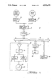
- FIG. 1 is a partial pictorial, partial block diagram of a digital data communications network which sets the operating environment for the analog gauges in accordance with the invention.
- FIG. 2 is illustrative of a change in deflection of an analog gauge needle from a current deflection position to a target deflection position as would be effected by the techniques of the present invention.
- FIG. 1 illustrates in block diagram form a preferred embodiment of a digital data communications network 10 used in vehicles with advanced electronic features that includes the analog gauges of this invention.
- a distance sensor 12 one of a plurality of transducers supplying a variety of data to an engine control unit (ECU 14), senses distance traveled by the vehicle.
- Another transducer such as an ignition pulse transducer 13 converts ignition pulse quantities into electrical signals equivalent to the number of engine crank shaft revolutions for determining RPM for use by an analog tachometer 19.
- analog tachometer in this embodiment employs an air-core gauge and functions basically in the same manner as the analog speedometer, and since the techniques of this invention apply to nearly any analog gauge adaptable to accept periodically computed or measured quantities, the description and application of the principles of the invention which follows will apply to operating an analog gauge as a speedometer.
- Distance sensor 12 a conventional electromechanical transducer, usually mounted on a portion of a drive train of a vehicle, acts as a ground switch for providing a series of ON and OFF ground switch closures grounding a pull-up resistor at a defined in rate proportion to the distance traveled by the vehicle; e.g., 8000 switch closures per mile traveled, to an input port of a computer circuit (not shown) in ECU 14.
- the computer circuit in ECU 14 increments a counter in response to each switch closure during a defined interval. At the end of that interval the count is transmitted over serial link 16 in a chosen message format. Since the counts are accumulated over a specific interval, the data can be interpreted as distance counts/time, or speed.
- the counts/time data in this embodiment consists of a message identification (ID) byte; i.e., an identification of the type parameter, and a data byte used to designate a digital number of a value proportional to the distance the vehicle traveled during a chosen time interval.
- ID message identification
- serial communication type transmitter/receiver devices within interface modules 17--17 and non-return-to-zero (NRZ) coding move data over link 16.
- NRZ non-return-to-zero
- other alternative codes such as NRZ inverted and Manchester coding may be used.
- the serial communication interfaces within the interface circuits convert standard digital logic level signals into, e.g., NRZ coded serial data for transmission over link 16.
- Body controller unit 18 in this embodiment, which intercepts the coded data broadcast by ECU 14 over link 16, processes and converts the distance/time number values into a coded message format usable by the D/A converting circuits within an analog speedometer 20. Then, within chosen transfer intervals, BCU 18 transmits coded messages to speedometer 20 at a rate suitable for updating an analog air-core gauge 28.
- a message sent over link 16 by BCU 18 to analog speedometer 20 comprises an identification byte, a data 0 byte and a data 1 byte.
- a byte in this embodiment comprises a start bit, eight (8) data bits and one (1) stop bit.
- Prior to the transmission of the message at least ten (10) bit times of idle (a high logic voltage level) are maintained on link 16. Then separate messages transmitted sequentially provide data for each analog gauge connected to link 16. The idle periods separate each message.
- Analog speedometer 20 which interfaces directly with link 16, intercepts the messages transmitted from BCU 18 at a rate of 7812.5 bits per second and then performs the process of converting the data into a form usable for updating the analog gauges such as gauge 28. It should be appreciated by those skilled in this art that other analog display mechanisms could be used instead of the air-core gauge, e.g., a stepper motor driven indicator gauge.
- ECU 14 Before explaining data procurement gap, transmission gap and needle movement smoothing procedures, the following provides a listing of the various constraints imposed on system 10. Firstly, the microprocessor located in ECU 14 has limitations imposed on the time used to procure distance data supplied to analog speedometer 20. Hence, ECU 14 transmits speed data over link 16 only during certain communication transfer intervals. Secondly, link 16, essentially a twisted pair of wires, has bandwidth limitations. Signal data rates over link 16 cannot exceed 10 kilobits/second. Thirdly, analog speedometer 20 requires continuous updating as the vehicle travels. Thus, the system must provide information to gauge 28 at an update rate that effects needle movement in a manner that the user can easily follow. Fourthly, smooth needle movement must occur without the needle sticking during translation even though the hardware circuits within the system do not address or aid smooth needle movement considerations. Fifthly, the design of the air-core gauge movement provides little mechanical damping in order to allow quick needle movement.
- ECU 14 counts the switch closures and transmits, synchronously, an accumulation of the counts or distance data over link 16 within, e.g., a 344 ms interval to BCU 18.
- BCU 18 translates the accumulated counts/time data into mi/hr data using a conversion factor as follows: ##EQU1##
- FIG. 2 illustrates a 90° gauge wherein speed ranges from 0 to 85 mph and input count numbers range from 0 to 255. It should be appreciated by those skilled in this art that the principles of this invention would apply to gauges capable of providing a maximum deflection from 0° to at least 360°.
- a microcontroller (MCU) 22 of analog speedometer 20 converts digital numbers into pulse-width modulated signals which drive H-drivers 24 and 26 for deflecting the needle of gauge 28 to a location proportional to the percentage that the number represents with respect to the number 255. Full deflection equals 255; no deflection equals zero. This other conversion factor follows: ##EQU2##
- This algorithm produces smooth needle movement by keeping track of the current needle deflection and the desired (or target) deflection based on an update number, Delta. It then moves the gauge needle linearly from its current position to the target position at a rate dictated by a Delta number at a chosen update rate. This update rate is chosen, taking into account the desired characteristic of needle movement, for the particular gauge being driven. If the magnitude of gauge movement can be large in one data update period, then the update rate must be fast to create the illusion of smooth gauge movement. Slowly changing gauges, such as a fuel gauge, can utilize a much slower update rate.
- the updating number Delta is defined as follows: ##EQU3##
- the data rate in this embodiment, 0.344 second, equals the rate at which new distance counts are received by BCU 18.
- the smoothing factor number permits introducing additional needle damping. The more the smoothing factor number exceeds one, the more the damping increases. In this embodiment, the smoothing factor is one.
- the update rate may vary from 8 Hz, if it is desired to conserve bus bandwidth, through 100 Hz, if extremely smooth gauge needle motion is desired. In the speedometer of this embodiment, the update rate is 32 Hz.
- BCU 18 must perform two primary tasks concurrently, namely compute deflection and Delta values for gauge 28 at a frequency of about 3 Hz and also update the current deflection by Delta at a 32 Hz rate.
- Tables 1 and 2 contain pseudo code statements representative of the machine code instructions the processor of BCU 18 executes to compute mph data substantially free of gaps between integer time/count data transmitted over link 16 and in a form that minimizes jerkiness in the gauge needle.
- the pseudo code statements a form of program development language, provides a verbal picture of the program functions much like a flowchart.
- the assembly language statements (not shown) which implement the pseudo code statements may be compiled into a form commensurate with the target computer assembly language and optimized for execution speed and RAM or ROM efficiency as the system requirements dictate.
- a suitable conventional assembler is used to generate the machine codes.
- the machine codes generated from the pseudo code statements are stored in a chosen location in ROM and used in a control algorithm by BCU 18 to generate mi/hr data.
- the asterisk * denotes the beginning of a statement
- the dash after the asterisk indicates the indentation level of the statement and /*comment*/defines a comment line.
- BCU 18 performs essentially two concurrent tasks, namely, computing TARGET DEFLECTION and Delta, and updating CURRENT DEFLECTION until CURRENT DEFLECTION equals TARGET DEFLECTION.
- the BCU 18 must execute the program depicted in Table 1 and, to determine DELTA and CURRENT DEFLECTION, it must execute the program depicted in Table 2.
- Table 3 is a record of the data flow and computations produced in the example operation of this system.
- Each line represents an event in the operation of the system with the first line showing the initial conditions of the example. Subsequent lines are arranged in chronological order with the first column showing the time at which each event happens.
- the lines represent two kinds of events. One is the transmission by ECU 14 and receipt by BCU 18 of the distance/time information which is used to compute speed. At this time the program of Table 1 is executed yielding the quantities Target Deflection and Delta. The second type of event happens every 1/32 second and at this time the program of Table 2 is executed resulting in an updated value for Current Deflection and the possible transmission of a new deflection command to the analog speedometer gauge 20.
- Table 3 shows the time of the event in the first column, the value of distance/time message received in the second column, the equivalent miles per hour of that message in the third column, and the values of Target Deflection and Delta computed at that time are shown in columns 4 and 5.
- the time in thirty-seconds of a second is shown in the first column and the current deflection computed at that time is shown in the sixth column.
- the seventh column shows the value of deflection transmitted, if any.
- FIG. 2 shows the layout of the speedometer gauge used in this example and how the gauge needle moves in response to the deflection commands sent by BCU 18. The numbers above the intermediate needle positions indicate the deflection count value for that position. This figure is not drawn to scale with respect to the needle position since each deflection count is about 1/3 of a degree which would cause the needle positions to be drawn overlapped.
- Table 3 illustrates the first second of operation of the case where a car has been travelling about 30 miles per hour so as to generate a steady stream of distance/time values of 23. At this point the needle is positioned at deflection count 90 and Delta is 0. The driver then accelerates steadily for a period of 5 seconds, reaching a speed of 50 miles per hour in that time.
- BCU 18 receives the first distance/time value of the acceleration period, a value of 24.
- BCU 18 computes a Target Deflection of 94.2. This is simply
- analog speedometer 20 finds SINE and COSINE values for the deflection command and generates appropriate pulsewidth modulated signals to the SINE and COSINE H-drivers 24 and 26. These drivers generate currents commensurate with the pulsewidth modulated signals in the two orthogonal coils of air core gauge 28 which cause gauge pointer 29 to move to a new position. Referring now to FIG. 2, the needle will move from the position labeled 90 to the position labeled 91.
- the needle will be moved 3 more times in the first interval. Then a new distance/time message is received from ECU 14, and, as a result, a new Target Deflection and Delta are computed and the process of incrementing Current Deflection is started again.
- the update rate can be lowered to 8 Hertz or even lower, thus conserving communications bus bandwidth.
Abstract
Description
              TABLE 1
______________________________________
TARGET AND DELTA COUNT NUMBERS
______________________________________
/*Convert distance counts/time data byte words to Target
Deflection and Delta count numbers */
/*A Target Deflection count number and Delta count number is
determined once every period (i.e., one every 344 ms)
/*Definitions */
/*DISTANCE is the latest distance/time data received from ECU
14 */
/*DATA INTERVAL is the length of time between receipt of
new raw data, 344 ms in this case*/
/*TARGET DEFLECTION is the position where the speedometer
needle should be based on the latest DISTANCE, computed in
this routine*/
/*CURRENT DEFLECTION is the current position of the
speedometer needle, computed in the routine of Table 2*/
/*DELTA is an update number of CURRENT DEFLECTION
that is computed in this routine based on TARGET DEFLEC-
TION and CURRENT DEFLECTION*/
/*UPDATE RATE is the rate BCU 18 updates CURRENT
DEFLECTION used in Table 1 and 2*/
/*SMOOTHING FACTOR is chosen during system design
to provide proper damping*/
*While Ignition On, DO
*Wait for new DISTANCE byte to be sent from ECU 14;
*mph number = (DISTANCE) * 1.30814;
*TARGET DEFLECTION =
mph number * 3 deflection counts/mph;
 ##STR1##
*Save TARGET DEFLECTION;
*Save DELTA;
*End While *
______________________________________
TABLE 2 ______________________________________ CURRENT DEFLECTION COUNT NUMBERS ______________________________________ *-While ignition of the vehicle ON, Do *---Get TARGET DEFLECTION; *---Get DELTA; *---Wait for UPDATE RATE time; *---If CURRENT DEFLECTION not = TARGET DEFLECTION *-----CURRENT DEFLECTION = CURRENT DEFLECTION + DELTA; *---Else *-----Null; *---If integer part of TARGET DEFLECTION has changed *-----Transmit CURRENT DEFLECTION toanalog speedometer 20; *---Else *-----Null; *-End While; End Program ______________________________________
94.2=24 * 1.30814 * 3 (4)
              TABLE 3
______________________________________
        Dis-                               Deflec-
        tance           Target      Current
                                           tion
        Re-             Deflec-     Deflec-
                                           Trans-
Time    ceived  MPH     tion  Delta tion   mitted
______________________________________
Initial 23      30.1    90.3  0.0000
                                    90.00
Condition
0.000   24      31.4    94.2  0.3815
 1/32                               90.38
 2/32                               90.76
 3/32                               91.14  91
 4/32                               91.53
 5/32                               91.91
 6/32                               92.29  92
 7/32                               92.67
 8/32                               93.05  93
 9/32                               93.43
10/32                               93.82
11/32                               94.20  94
0.344   25      32.7    98.1  0.3546
12/32                               94.55
12/32                               94.91
13/32                               95.26  95
14/32                               95.62
15/32                               95.97
16/32                               96.32  96
17/32                               96.68
18/32                               97.03  97
19/32                               97.39
20/32                               97.74
21/32                               98.10  98
22/32                               98.45
0.688   26      34.0    102.0 0.3223
23/32                               98.77
24/32                               99.10  99
25/32                               99.42
26/32                               99.74
27/32                               100.06 100
28/32                               100.39
29/32                               100.71
30/32                               101.03 101
31/32                               101.35
32/32                               101.68
1.032   27      35.3    105.9 0.3838
33/32                               102.06 102
______________________________________
Claims (4)
Priority Applications (1)
| Application Number | Priority Date | Filing Date | Title |
|---|---|---|---|
| US07/288,373 US4939675A (en) | 1988-12-22 | 1988-12-22 | Digital system for controlling mechanical instrument gauges |
Applications Claiming Priority (1)
| Application Number | Priority Date | Filing Date | Title |
|---|---|---|---|
| US07/288,373 US4939675A (en) | 1988-12-22 | 1988-12-22 | Digital system for controlling mechanical instrument gauges |
Publications (1)
| Publication Number | Publication Date |
|---|---|
| US4939675A true US4939675A (en) | 1990-07-03 |
Family
ID=23106827
Family Applications (1)
| Application Number | Title | Priority Date | Filing Date |
|---|---|---|---|
| US07/288,373 Expired - Lifetime US4939675A (en) | 1988-12-22 | 1988-12-22 | Digital system for controlling mechanical instrument gauges |
Country Status (1)
| Country | Link |
|---|---|
| US (1) | US4939675A (en) |
Cited By (24)
| Publication number | Priority date | Publication date | Assignee | Title |
|---|---|---|---|---|
| US5001930A (en) * | 1989-11-06 | 1991-03-26 | Acustar, Inc. | Speedometer assembly |
| US5063344A (en) * | 1990-03-05 | 1991-11-05 | Delco Electronics Corporation | Mode selectable interface circuit for an air core gage controller |
| US5105150A (en) * | 1989-06-29 | 1992-04-14 | Paul Liu | Wide-band programmable tachometer and speedometer/odometer apparatus |
| US5142412A (en) * | 1988-12-19 | 1992-08-25 | Jaeger | Circuit for controlling a ration meter |
| WO1992019992A2 (en) * | 1991-05-09 | 1992-11-12 | Nu-Tech And Engineering, Inc. | Instrument display method and system for passenger vehicle |
| US5214597A (en) * | 1988-11-09 | 1993-05-25 | Yazaki Corporation | Cross coil type indicator |
| US5218291A (en) * | 1991-03-26 | 1993-06-08 | Rohm Co., Ltd. | Meter and meter driving system with indication fluctuation suppression and enhancement |
| US5335211A (en) * | 1987-12-25 | 1994-08-02 | Citizen Watch Co., Ltd. | Display device by means of a hand |
| US5357451A (en) * | 1993-01-07 | 1994-10-18 | Ford Motor Company | Digital system controller with programmable ranges for analog speedometer and tachometer gauges |
| US5410244A (en) * | 1993-05-10 | 1995-04-25 | Delco Electronics Corporation | Air core gauge testing method and apparatus utilizing magnetic coupling between gauge coils |
| US5561374A (en) * | 1994-11-03 | 1996-10-01 | Ford Motor Company | Method for displaying a vehicle speed measurement with improved display response characteristics |
| US5673192A (en) * | 1993-03-17 | 1997-09-30 | Honda Giken Kogyo Kabushiki Kaisha | Electrical equipment control system for a vehicle utilizing one central processing unit |
| US5696704A (en) * | 1995-06-07 | 1997-12-09 | Vdo North America, Inc. | Non-linear scale instrument |
| US6018302A (en) * | 1996-09-05 | 2000-01-25 | Alliedsignal Inc. | Mechanical pointer drive for avionics display |
| US6112138A (en) * | 1993-09-30 | 2000-08-29 | Navistar International Transportation Corp | Programming response of electronically-controlled gauges |
| US6118370A (en) * | 1998-08-10 | 2000-09-12 | Ford Motor Company | Two-stage temperature gauge with added winding |
| US6216062B1 (en) * | 1999-11-11 | 2001-04-10 | Visteon Global Technologies, Inc. | Step-less vehicle display allowing irregular update intervals |
| US6317037B1 (en) | 1997-11-03 | 2001-11-13 | Atoma International Corp. | Virtual instrument panel |
| US6404333B1 (en) | 1997-11-03 | 2002-06-11 | Invotronics Manufacturing | Gauge instrument for use in a motor vehicle |
| US20040006449A1 (en) * | 2002-07-08 | 2004-01-08 | John Rubis | Direct data bus instrument |
| US20050151633A1 (en) * | 2003-10-29 | 2005-07-14 | De Sisti Lighting S.P.A. | Electronic gauge translator for ECU equipped engines |
| US20060266273A1 (en) * | 2005-03-14 | 2006-11-30 | Todd Westberg | System and method of modular vehicle gauge system and illumination |
| US20070006101A1 (en) * | 2005-06-20 | 2007-01-04 | Brunswick Corporation | Instrumentation interface display customization |
| US9341501B1 (en) | 2013-03-15 | 2016-05-17 | Brunswick Corporation | Analog gauge driver |
Citations (14)
| Publication number | Priority date | Publication date | Assignee | Title |
|---|---|---|---|---|
| US4152645A (en) * | 1977-05-26 | 1979-05-01 | Acurex Corporation | Method and apparatus for producing an analogue output proportional to rotational speed employing digital to analogue conversion |
| US4230984A (en) * | 1979-03-22 | 1980-10-28 | General Motors Corporation | Method and apparatus for driving an air core gage |
| US4356445A (en) * | 1980-07-10 | 1982-10-26 | Cherry Semiconductor Corporation | Method and apparatus for driving air core meter movements |
| US4494183A (en) * | 1982-06-17 | 1985-01-15 | Honeywell Inc. | Process variable transmitter having a non-interacting operating range adjustment |
| US4506216A (en) * | 1981-06-16 | 1985-03-19 | Honda Giken Kogyo Kabushiki Kaisha | Speed meter system for vehicle |
| US4556943A (en) * | 1983-05-27 | 1985-12-03 | Allied Corporation | Multiprocessing microprocessor based engine control system for an internal combustion engine |
| US4567466A (en) * | 1982-12-08 | 1986-01-28 | Honeywell Inc. | Sensor communication system |
| US4587605A (en) * | 1984-01-19 | 1986-05-06 | Matsushita Electric Industrial Co., Ltd. | Inverter-drive controlling apparatus |
| US4608532A (en) * | 1982-12-03 | 1986-08-26 | Solomat S.A. | Multi-probe metering apparatus |
| US4628314A (en) * | 1983-11-08 | 1986-12-09 | Hitachi, Ltd. | Method and apparatus for detecting position and velocity of moving body |
| US4751442A (en) * | 1984-12-27 | 1988-06-14 | Fanuc Ltd | Servomotor drive control system |
| US4777618A (en) * | 1984-07-19 | 1988-10-11 | Nippondenso Co., Ltd. | Method of storing, indicating or producing signals and apparatus for recording or producing signals |
| US4779213A (en) * | 1987-05-27 | 1988-10-18 | Chrysler Motors Corporation | Electronic digital speedometer for a multi-measurand data communication system |
| US4791569A (en) * | 1985-03-18 | 1988-12-13 | Honda Giken Kogyo Kabushiki Kaisha | Electronic control system for internal combustion engines |
-
1988
- 1988-12-22 US US07/288,373 patent/US4939675A/en not_active Expired - Lifetime
Patent Citations (14)
| Publication number | Priority date | Publication date | Assignee | Title |
|---|---|---|---|---|
| US4152645A (en) * | 1977-05-26 | 1979-05-01 | Acurex Corporation | Method and apparatus for producing an analogue output proportional to rotational speed employing digital to analogue conversion |
| US4230984A (en) * | 1979-03-22 | 1980-10-28 | General Motors Corporation | Method and apparatus for driving an air core gage |
| US4356445A (en) * | 1980-07-10 | 1982-10-26 | Cherry Semiconductor Corporation | Method and apparatus for driving air core meter movements |
| US4506216A (en) * | 1981-06-16 | 1985-03-19 | Honda Giken Kogyo Kabushiki Kaisha | Speed meter system for vehicle |
| US4494183A (en) * | 1982-06-17 | 1985-01-15 | Honeywell Inc. | Process variable transmitter having a non-interacting operating range adjustment |
| US4608532A (en) * | 1982-12-03 | 1986-08-26 | Solomat S.A. | Multi-probe metering apparatus |
| US4567466A (en) * | 1982-12-08 | 1986-01-28 | Honeywell Inc. | Sensor communication system |
| US4556943A (en) * | 1983-05-27 | 1985-12-03 | Allied Corporation | Multiprocessing microprocessor based engine control system for an internal combustion engine |
| US4628314A (en) * | 1983-11-08 | 1986-12-09 | Hitachi, Ltd. | Method and apparatus for detecting position and velocity of moving body |
| US4587605A (en) * | 1984-01-19 | 1986-05-06 | Matsushita Electric Industrial Co., Ltd. | Inverter-drive controlling apparatus |
| US4777618A (en) * | 1984-07-19 | 1988-10-11 | Nippondenso Co., Ltd. | Method of storing, indicating or producing signals and apparatus for recording or producing signals |
| US4751442A (en) * | 1984-12-27 | 1988-06-14 | Fanuc Ltd | Servomotor drive control system |
| US4791569A (en) * | 1985-03-18 | 1988-12-13 | Honda Giken Kogyo Kabushiki Kaisha | Electronic control system for internal combustion engines |
| US4779213A (en) * | 1987-05-27 | 1988-10-18 | Chrysler Motors Corporation | Electronic digital speedometer for a multi-measurand data communication system |
Cited By (29)
| Publication number | Priority date | Publication date | Assignee | Title |
|---|---|---|---|---|
| US5335211A (en) * | 1987-12-25 | 1994-08-02 | Citizen Watch Co., Ltd. | Display device by means of a hand |
| US5214597A (en) * | 1988-11-09 | 1993-05-25 | Yazaki Corporation | Cross coil type indicator |
| US5142412A (en) * | 1988-12-19 | 1992-08-25 | Jaeger | Circuit for controlling a ration meter |
| US5105150A (en) * | 1989-06-29 | 1992-04-14 | Paul Liu | Wide-band programmable tachometer and speedometer/odometer apparatus |
| US5001930A (en) * | 1989-11-06 | 1991-03-26 | Acustar, Inc. | Speedometer assembly |
| US5063344A (en) * | 1990-03-05 | 1991-11-05 | Delco Electronics Corporation | Mode selectable interface circuit for an air core gage controller |
| US5218291A (en) * | 1991-03-26 | 1993-06-08 | Rohm Co., Ltd. | Meter and meter driving system with indication fluctuation suppression and enhancement |
| WO1992019992A2 (en) * | 1991-05-09 | 1992-11-12 | Nu-Tech And Engineering, Inc. | Instrument display method and system for passenger vehicle |
| WO1992019992A3 (en) * | 1991-05-09 | 1993-01-21 | Nu Tech And Engineering Inc | Instrument display method and system for passenger vehicle |
| US5406303A (en) * | 1991-05-09 | 1995-04-11 | Nu-Tech And Engineering, Inc. | Instrument display method and system for passenger vehicle |
| US5825338A (en) * | 1991-05-09 | 1998-10-20 | Atoma International Corp. | Instrument display method and system for passenger vehicle |
| US5357451A (en) * | 1993-01-07 | 1994-10-18 | Ford Motor Company | Digital system controller with programmable ranges for analog speedometer and tachometer gauges |
| US5673192A (en) * | 1993-03-17 | 1997-09-30 | Honda Giken Kogyo Kabushiki Kaisha | Electrical equipment control system for a vehicle utilizing one central processing unit |
| US5410244A (en) * | 1993-05-10 | 1995-04-25 | Delco Electronics Corporation | Air core gauge testing method and apparatus utilizing magnetic coupling between gauge coils |
| US6112138A (en) * | 1993-09-30 | 2000-08-29 | Navistar International Transportation Corp | Programming response of electronically-controlled gauges |
| US5561374A (en) * | 1994-11-03 | 1996-10-01 | Ford Motor Company | Method for displaying a vehicle speed measurement with improved display response characteristics |
| US5696704A (en) * | 1995-06-07 | 1997-12-09 | Vdo North America, Inc. | Non-linear scale instrument |
| US6018302A (en) * | 1996-09-05 | 2000-01-25 | Alliedsignal Inc. | Mechanical pointer drive for avionics display |
| US6317037B1 (en) | 1997-11-03 | 2001-11-13 | Atoma International Corp. | Virtual instrument panel |
| US6404333B1 (en) | 1997-11-03 | 2002-06-11 | Invotronics Manufacturing | Gauge instrument for use in a motor vehicle |
| US6118370A (en) * | 1998-08-10 | 2000-09-12 | Ford Motor Company | Two-stage temperature gauge with added winding |
| US6216062B1 (en) * | 1999-11-11 | 2001-04-10 | Visteon Global Technologies, Inc. | Step-less vehicle display allowing irregular update intervals |
| US20040006449A1 (en) * | 2002-07-08 | 2004-01-08 | John Rubis | Direct data bus instrument |
| US6816801B2 (en) * | 2002-07-08 | 2004-11-09 | Maxima Technologies & Systems, Inc. | Direct data bus instrument |
| US20050151633A1 (en) * | 2003-10-29 | 2005-07-14 | De Sisti Lighting S.P.A. | Electronic gauge translator for ECU equipped engines |
| US20060266273A1 (en) * | 2005-03-14 | 2006-11-30 | Todd Westberg | System and method of modular vehicle gauge system and illumination |
| US20070006101A1 (en) * | 2005-06-20 | 2007-01-04 | Brunswick Corporation | Instrumentation interface display customization |
| US7441189B2 (en) | 2005-06-20 | 2008-10-21 | Navico International Limited | Instrumentation interface display customization |
| US9341501B1 (en) | 2013-03-15 | 2016-05-17 | Brunswick Corporation | Analog gauge driver |
Similar Documents
| Publication | Publication Date | Title |
|---|---|---|
| US4939675A (en) | Digital system for controlling mechanical instrument gauges | |
| KR100253600B1 (en) | Drive apparatus for stepping motor type meter | |
| US4227150A (en) | System for indicating measured values | |
| EP0609624B1 (en) | Digital system controller with programmable ranges for analog speedometer and tachometer gauges | |
| US5103413A (en) | Travel detecting apparatus | |
| US5063344A (en) | Mode selectable interface circuit for an air core gage controller | |
| US5869776A (en) | Method and apparatus for receiving and displaying digital data | |
| US4779213A (en) | Electronic digital speedometer for a multi-measurand data communication system | |
| KR20030033263A (en) | velocity signal shifting device and method | |
| US4930094A (en) | Vehicle serial bus, mechanical instrument cluster odometer therefor | |
| EP0588582B1 (en) | Control circuit for a pointer instrument in a dashboard | |
| CN100425477C (en) | Pulse generating apparatus and vehicle display apparatus having that apparatus | |
| EP1041388B1 (en) | Method for driving meter | |
| GB1587955A (en) | Circuit arrangement for measuring speed and distance travelled particularly for tachographs | |
| US6216062B1 (en) | Step-less vehicle display allowing irregular update intervals | |
| GB2277619A (en) | A motor vehicle fuel information system | |
| JP3106462B2 (en) | Driving device for indicating instrument | |
| JP3609367B2 (en) | Pulse converter | |
| US5631430A (en) | Method and apparatus for enhanced gauge resolution | |
| JPH0514206B2 (en) | ||
| JPH05336575A (en) | Multiplex transmission method for vehicle | |
| Taylor et al. | Practical Electric Speedometer System for Passenger Car Applications | |
| JP2000137044A (en) | Driving method for instrument | |
| SU1053121A1 (en) | Device for monitoring operation of equipment | |
| JPH0581589A (en) | Measuring instrument for vehicle by multiplex communication |
Legal Events
| Date | Code | Title | Description |
|---|---|---|---|
| AS | Assignment |
Owner name: CHRYSLER MOTORS CORPORATION, .A DE CORP., MICHIGAN Free format text: ASSIGNMENT OF ASSIGNORS INTEREST.;ASSIGNOR:LUITJE, WILLIAM V.;REEL/FRAME:005013/0415 Effective date: 19881220 |
|
| STCF | Information on status: patent grant |
Free format text: PATENTED CASE |
|
| FEPP | Fee payment procedure |
Free format text: PAYOR NUMBER ASSIGNED (ORIGINAL EVENT CODE: ASPN); ENTITY STATUS OF PATENT OWNER: LARGE ENTITY |
|
| FPAY | Fee payment |
Year of fee payment: 4 |
|
| FPAY | Fee payment |
Year of fee payment: 8 |
|
| SULP | Surcharge for late payment | ||
| FPAY | Fee payment |
Year of fee payment: 12 |
|
| AS | Assignment |
Owner name: SIEMENS VDO AUTOMOTIVE ELECTRONICS CORPORATION, AL Free format text: ASSIGNMENT OF ASSIGNORS INTEREST;ASSIGNOR:DAIMLERCHRYSLER CORPORATION;REEL/FRAME:016059/0722 Effective date: 20040401 |
|
| AS | Assignment |
Owner name: SIEMENS VDO AUTOMOTIVE ELECTRONICS CORPORATION, AL Free format text: ASSIGNMENT OF ASSIGNORS INTEREST;ASSIGNOR:DAIMLERCHRYSLER CORPORATION;REEL/FRAME:016216/0035 Effective date: 20040401 |
|
| AS | Assignment |
Owner name: WILMINGTON TRUST COMPANY, DELAWARE Free format text: GRANT OF SECURITY INTEREST IN PATENT RIGHTS - FIRST PRIORITY;ASSIGNOR:CHRYSLER LLC;REEL/FRAME:019773/0001 Effective date: 20070803 Owner name: WILMINGTON TRUST COMPANY,DELAWARE Free format text: GRANT OF SECURITY INTEREST IN PATENT RIGHTS - FIRST PRIORITY;ASSIGNOR:CHRYSLER LLC;REEL/FRAME:019773/0001 Effective date: 20070803 |
|
| AS | Assignment |
Owner name: WILMINGTON TRUST COMPANY, DELAWARE Free format text: GRANT OF SECURITY INTEREST IN PATENT RIGHTS - SECOND PRIORITY;ASSIGNOR:CHRYSLER LLC;REEL/FRAME:019767/0810 Effective date: 20070803 Owner name: WILMINGTON TRUST COMPANY,DELAWARE Free format text: GRANT OF SECURITY INTEREST IN PATENT RIGHTS - SECOND PRIORITY;ASSIGNOR:CHRYSLER LLC;REEL/FRAME:019767/0810 Effective date: 20070803 |
|
| AS | Assignment |
Owner name: US DEPARTMENT OF THE TREASURY, DISTRICT OF COLUMBI Free format text: GRANT OF SECURITY INTEREST IN PATENT RIGHTS - THIR;ASSIGNOR:CHRYSLER LLC;REEL/FRAME:022259/0188 Effective date: 20090102 Owner name: US DEPARTMENT OF THE TREASURY,DISTRICT OF COLUMBIA Free format text: GRANT OF SECURITY INTEREST IN PATENT RIGHTS - THIR;ASSIGNOR:CHRYSLER LLC;REEL/FRAME:022259/0188 Effective date: 20090102 |
|
| AS | Assignment |
Owner name: CHRYSLER LLC, MICHIGAN Free format text: RELEASE BY SECURED PARTY;ASSIGNOR:US DEPARTMENT OF THE TREASURY;REEL/FRAME:022902/0164 Effective date: 20090608 Owner name: CHRYSLER LLC,MICHIGAN Free format text: RELEASE BY SECURED PARTY;ASSIGNOR:US DEPARTMENT OF THE TREASURY;REEL/FRAME:022902/0164 Effective date: 20090608 |
|
| AS | Assignment |
Owner name: CHRYSLER LLC, MICHIGAN Free format text: RELEASE OF SECURITY INTEREST IN PATENT RIGHTS - FIRST PRIORITY;ASSIGNOR:WILMINGTON TRUST COMPANY;REEL/FRAME:022910/0498 Effective date: 20090604 Owner name: CHRYSLER LLC, MICHIGAN Free format text: RELEASE OF SECURITY INTEREST IN PATENT RIGHTS - SECOND PRIORITY;ASSIGNOR:WILMINGTON TRUST COMPANY;REEL/FRAME:022910/0740 Effective date: 20090604 Owner name: CHRYSLER LLC,MICHIGAN Free format text: RELEASE OF SECURITY INTEREST IN PATENT RIGHTS - FIRST PRIORITY;ASSIGNOR:WILMINGTON TRUST COMPANY;REEL/FRAME:022910/0498 Effective date: 20090604 Owner name: CHRYSLER LLC,MICHIGAN Free format text: RELEASE OF SECURITY INTEREST IN PATENT RIGHTS - SECOND PRIORITY;ASSIGNOR:WILMINGTON TRUST COMPANY;REEL/FRAME:022910/0740 Effective date: 20090604 |