US4948667A - Magnetic head - Google Patents
Magnetic head Download PDFInfo
- Publication number
- US4948667A US4948667A US07/026,620 US2662087A US4948667A US 4948667 A US4948667 A US 4948667A US 2662087 A US2662087 A US 2662087A US 4948667 A US4948667 A US 4948667A
- Authority
- US
- United States
- Prior art keywords
- magnetic
- metal thin
- magnetic head
- intermediate layer
- writing
- Prior art date
- Legal status (The legal status is an assumption and is not a legal conclusion. Google has not performed a legal analysis and makes no representation as to the accuracy of the status listed.)
- Expired - Fee Related
Links
Images
Classifications
-
- G—PHYSICS
- G11—INFORMATION STORAGE
- G11B—INFORMATION STORAGE BASED ON RELATIVE MOVEMENT BETWEEN RECORD CARRIER AND TRANSDUCER
- G11B5/00—Recording by magnetisation or demagnetisation of a record carrier; Reproducing by magnetic means; Record carriers therefor
- G11B5/127—Structure or manufacture of heads, e.g. inductive
- G11B5/187—Structure or manufacture of the surface of the head in physical contact with, or immediately adjacent to the recording medium; Pole pieces; Gap features
-
- G—PHYSICS
- G11—INFORMATION STORAGE
- G11B—INFORMATION STORAGE BASED ON RELATIVE MOVEMENT BETWEEN RECORD CARRIER AND TRANSDUCER
- G11B5/00—Recording by magnetisation or demagnetisation of a record carrier; Reproducing by magnetic means; Record carriers therefor
- G11B5/127—Structure or manufacture of heads, e.g. inductive
- G11B5/147—Structure or manufacture of heads, e.g. inductive with cores being composed of metal sheets, i.e. laminated cores with cores composed of isolated magnetic layers, e.g. sheets
-
- G—PHYSICS
- G11—INFORMATION STORAGE
- G11B—INFORMATION STORAGE BASED ON RELATIVE MOVEMENT BETWEEN RECORD CARRIER AND TRANSDUCER
- G11B5/00—Recording by magnetisation or demagnetisation of a record carrier; Reproducing by magnetic means; Record carriers therefor
- G11B5/127—Structure or manufacture of heads, e.g. inductive
- G11B5/187—Structure or manufacture of the surface of the head in physical contact with, or immediately adjacent to the recording medium; Pole pieces; Gap features
- G11B5/255—Structure or manufacture of the surface of the head in physical contact with, or immediately adjacent to the recording medium; Pole pieces; Gap features comprising means for protection against wear
-
- Y—GENERAL TAGGING OF NEW TECHNOLOGICAL DEVELOPMENTS; GENERAL TAGGING OF CROSS-SECTIONAL TECHNOLOGIES SPANNING OVER SEVERAL SECTIONS OF THE IPC; TECHNICAL SUBJECTS COVERED BY FORMER USPC CROSS-REFERENCE ART COLLECTIONS [XRACs] AND DIGESTS
- Y10—TECHNICAL SUBJECTS COVERED BY FORMER USPC
- Y10S—TECHNICAL SUBJECTS COVERED BY FORMER USPC CROSS-REFERENCE ART COLLECTIONS [XRACs] AND DIGESTS
- Y10S428/00—Stock material or miscellaneous articles
- Y10S428/90—Magnetic feature
-
- Y—GENERAL TAGGING OF NEW TECHNOLOGICAL DEVELOPMENTS; GENERAL TAGGING OF CROSS-SECTIONAL TECHNOLOGIES SPANNING OVER SEVERAL SECTIONS OF THE IPC; TECHNICAL SUBJECTS COVERED BY FORMER USPC CROSS-REFERENCE ART COLLECTIONS [XRACs] AND DIGESTS
- Y10—TECHNICAL SUBJECTS COVERED BY FORMER USPC
- Y10T—TECHNICAL SUBJECTS COVERED BY FORMER US CLASSIFICATION
- Y10T428/00—Stock material or miscellaneous articles
- Y10T428/11—Magnetic recording head
- Y10T428/1171—Magnetic recording head with defined laminate structural detail
-
- Y—GENERAL TAGGING OF NEW TECHNOLOGICAL DEVELOPMENTS; GENERAL TAGGING OF CROSS-SECTIONAL TECHNOLOGIES SPANNING OVER SEVERAL SECTIONS OF THE IPC; TECHNICAL SUBJECTS COVERED BY FORMER USPC CROSS-REFERENCE ART COLLECTIONS [XRACs] AND DIGESTS
- Y10—TECHNICAL SUBJECTS COVERED BY FORMER USPC
- Y10T—TECHNICAL SUBJECTS COVERED BY FORMER US CLASSIFICATION
- Y10T428/00—Stock material or miscellaneous articles
- Y10T428/26—Web or sheet containing structurally defined element or component, the element or component having a specified physical dimension
- Y10T428/263—Coating layer not in excess of 5 mils thick or equivalent
- Y10T428/264—Up to 3 mils
- Y10T428/265—1 mil or less
Definitions
- the present invention relates to a magnetic head for write and read of information on a magnetic recording medium such as a magnetic disc or magnetic tape.
- a magnetic head for use in a magnetic disc type or magnetic tape type recording and reproducing device.
- a magnetic head the core of which is at least in part composed of a laminate comprising magnetic metal thin layers and non-magnetic intermediate layers.
- the intermediate layer plays the role of magnetically isolating the magnetic metal thin layers from each other to diminish magnetic loss due to eddy current and prevent the lowering of magnetic recording and reproducing properties.
- silicon dioxide SiO 2
- the intermediate layer of SiO 2 is required to have a thickness of at least 0.1 ⁇ m in order to afford enough insulation.
- this SiO 2 intermediate layer is much harder than the magnetic metal thin layer made of an amorphous metal or permalloy, such intermediate layer can hardly be abraded.
- the desired accuracy of fitting between the magnetic head and a magnetic recording medium should be obtained by abrading the fitting surface of the magnetic head.
- the abraded end of the intermediate layer projects beyond the abraded end of the magnetic metal thin layer.
- the desired high accuracy of fitting cannot be obtained in prior art magnetic heads.
- the magnetic metal thin layer is more fastly worn away than the intermediate layer during sliding of the magnetic disc or magnetic tape on the magnetic head. Therefore, the intermediate layer is in a state projected beyond the magnetic metal thin layer.
- FIG. 1 shows the above-mentioned state.
- reference number 1 denotes a magnetic metal thin layer, 2 an intermediate layer, 3 a magnetic recording medium.
- the end of the intermediate layer 2 projects beyond the end of the magnetic metal thin layer 1 after finishing or during sliding of a recording medium on the magnetic head and, as a result, the magnetic recording medium 3 rises up in the vicinity of the intermediate layers 2.
- the projected intermediate layers 2 injure the magnetic recording medium and, therefore, the durability of the magnetic recording medium is lowered. Moreover, the sufficient contact of the magnetic head and the magnetic recording medium cannot be achieved and, therefore, write or read of information are partially impossible to effect.
- FIG. 2 schematically shows the state of the magnetic recording medium 3 into which information is partially not written. That is, FIG. 2 shows that on the magnetic medium there are present non-magnetized or weakly magnetized portions 4 and magnetized portions 5.
- the non-magnetized or weakly magnetized portions are formed in a stripe pattern on the magnetic recording medium 3 in a traveling direction thereof.
- the non-magnetized or weakly magnetized portions of the magnetic recording medium correspond to the portions forced to rise up due to the projected ends of the intermediate layers 2.
- Such formation of the non-magnetized or weakly magnetized portions should absolutely be avoided in order to obtain a high reliability of a magnetic recording device.
- One object of the present invention is to provide a magnetic head which prevents any non-magnetized or weakly magnetized portions from being formed on a magnetic recording medium.
- Another object of the present invention is to provide a magnetic head which does not injure a magnetic recording medium during contacting of the magnetic head with the medium.
- a further object of the present invention is to provide a magnetic head which is in good contact with a magnetic recording medium and has a high reliability.
- a magnetic head the core of which is at least in part composed of a plurality of magnetic metal thin layers laminated and a non-magnetic intermediate layer(s) for inhibiting magnetic loss due to eddy current, which layers are disposed between the magnetic metal thin layers.
- the metal may be any one used generally in the art, such as a cobalt base amorphous alloy or permalloy.
- a material having a Vickers hardness Hv of not less 200 to less than 1,200 is used.
- This material may be a metal oxide such as SiO, Al 2 O 3 , MgO and BaTiO 3 .
- FIG. 1 is a partially enlarged diagram of a prior art magnetic head.
- FIG. 2 is a diagram showing the state of a recording medium recorded by using a prior art magnetic head.
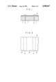
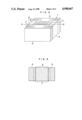
- FIG. 3 is a diagram of a magnetic head according to an embodiment of the present invention.
- FIG. 4 is a cross-sectional view of the magnetic head along line A--A of FIG. 3.
- metal oxides there are generally believed to be a close correlation between a hardness and a mechanical strength such as a yield strength, fracture strength or tensile strength.
- the "wear” may be regarded as microscopic fracture. Therefore, it can be considered that there is a correlation between the wear resistance and the hardness. In fact, a harder material has a tendency of possessing a higher wear resistance.
- the present inventors have found that a non-magnetic material having a lower hardness than that of SiO 2 can successfully be used as the intermediate layer of a magnetic head to diminish or eliminate the projection of the intermediate layer.
- the Vickers hardness of SiO 2 is about 1,200 and has such drawbacks as mentioned above.
- a material for the intermediate layer used in the present invention should have a Vickers hardness of less than 1,200.
- the Vickers hardness of a magnetic metal used for the magnetic head is 600 to 800 for a cobalt base amorphous alloy and about 200 for a Mo-permalloy. Therefore, the use of a material having a much lower Vickers hardness than the above-mentioned Vickers hardness as the intermediate layer would result in producing the same drawbacks as mentioned above, that is, the intermediate layer is more fastly worn than the magnetic metal thin layer, so that the thin layer projects beyond the intermediate layer. Therefore, the Vickers hardness of the intermediate layer should be not less than 200.
- non-magnetic material having a Vickers hardness of not less than 200 to less than 1,200, there are, for example, MgO (Hv:about 600), Al 2 O 3 (Hv:about 800) and BaTiO 3 (Hv:about 1,000).
- such a material having a Vickers hardness near that of the magnetic metal thin layer is preferably used as the intermediate layer to provide a magnetic head having no projections or recesses thereon.
- FIGS. 3 and 4 diagramatically illustrate one of the magnetic heads of the present invention.
- three magnetic metal thin layers 7 are formed on one side of a substrate 6.
- This substrate may be made of a material, such as Mn-Zn ferrite, Zn ferrite or calcium titanate, which is generally used in the art.
- Two intermediate layers 8 are disposed between the magnetic metal thin layers 7.
- the intermediate layer is formed on the magnetic metal thin layer by a usual film-forming method such as sputtering or vapor deposition.
- the thus formed half core body of the magnetic head is joined to another half core body through a magnetic gap 10. This joining is reinforced by glass layers 9.
- the thickness of the magnetic metal thin layer 7 varies depending upon a skin depth but it is preferably in the range of about 10 to 25 ⁇ m at a recording signal of 5 MHz
- the thickness of the intermediate layer 8 varies depending upon a track width but it is preferably in the range of about 0.05 to 3.0 ⁇ m, more preferably in the range of about 0.05 to 0.3 ⁇ m.
- Mn-Zn ferrite was used as the substrate 6 for the magnetic head.
- a Co-Ta-Nb base amorphous alloy having a Vickers hardness of about 600 was used as the magnetic metal thin layers 7.
- BaTiO 3 having a Vickers hardness of about 600 was used as the intermediate layers 8.
- the thin layers were 15 ⁇ m thick, and the intermediate layers were 0.15 ⁇ m thick.
- the same magnetic head was provided, except that SiO 2 was substituted for BaTiO 3 as the intermediate layer.
- the durability of magnetic recording medium was measured by using a magnetic disc prepared by forming a magnetic layer on a base film of polyester, mounting this disc on a disc-driving device and rotating the disc to repeat write and read of information on the disc at the same position thereof.
- the durability is represented by the number of rotations attained until the output power was reduced by 30%, i.e., down to 70% of the original output power.
- the durability of a magnetic recording medium on the magnetic head of the present invention is superior to that on the magnetic head of the prior art.
- the reproducing characteristics of the magnetic head were not deteriorated. It follows that the magnetic head of the present invention is more reliable than that of the prior art.
- BaTiO 3 was used as the intermediate layer but, of course, other materials such as SiO, Al 2 O 3 and MgO, having a Vickers hardness of not less than 200 to less than 1,200 may be used in the present invention.
Abstract
A magnetic head for write and read of information, the core of which is at least in part composed of magnetic metal thin layers and non-magnetic intermediate metal oxide layers alternately laminated is provided. The metal is a cobalt base amorphous alloy or permalloy and the metal oxide is selected from SiO, Al2 O3, MgO and BaTiO3, which has a Vickers hardness of not less than 200 to less than 1,200. The use of the magnetic head does not injure a magnetic recording medium and contributes to improvement of the durability of the magnetic recording medium.
Description
1. Field of the Invention
The present invention relates to a magnetic head for write and read of information on a magnetic recording medium such as a magnetic disc or magnetic tape.
2. Prior Art
There have hitherto been developed various kinds of magnetic heads for use in a magnetic disc type or magnetic tape type recording and reproducing device. As one of such magnetic heads is known a magnetic head, the core of which is at least in part composed of a laminate comprising magnetic metal thin layers and non-magnetic intermediate layers.
In this kind of magnetic head, the intermediate layer plays the role of magnetically isolating the magnetic metal thin layers from each other to diminish magnetic loss due to eddy current and prevent the lowering of magnetic recording and reproducing properties. As a material for the intermediate layer, silicon dioxide (SiO2) is normally used. The intermediate layer of SiO2 is required to have a thickness of at least 0.1 μm in order to afford enough insulation. However, since this SiO2 intermediate layer is much harder than the magnetic metal thin layer made of an amorphous metal or permalloy, such intermediate layer can hardly be abraded.
In preparing a magnetic head using the above-mentioned laminate, the desired accuracy of fitting between the magnetic head and a magnetic recording medium should be obtained by abrading the fitting surface of the magnetic head. As is clear from the foregoing, there is a great difference in a rate of abrasion between the magnetic metal thin layer and the intermediate layer and, therefore, the abraded end of the intermediate layer projects beyond the abraded end of the magnetic metal thin layer. For this reason, the desired high accuracy of fitting cannot be obtained in prior art magnetic heads. Moreover, the magnetic metal thin layer is more fastly worn away than the intermediate layer during sliding of the magnetic disc or magnetic tape on the magnetic head. Therefore, the intermediate layer is in a state projected beyond the magnetic metal thin layer.
FIG. 1 shows the above-mentioned state. In FIG. 1, reference number 1 denotes a magnetic metal thin layer, 2 an intermediate layer, 3 a magnetic recording medium. As is seen from FIG. 1, the end of the intermediate layer 2 projects beyond the end of the magnetic metal thin layer 1 after finishing or during sliding of a recording medium on the magnetic head and, as a result, the magnetic recording medium 3 rises up in the vicinity of the intermediate layers 2.
Thus, the projected intermediate layers 2 injure the magnetic recording medium and, therefore, the durability of the magnetic recording medium is lowered. Moreover, the sufficient contact of the magnetic head and the magnetic recording medium cannot be achieved and, therefore, write or read of information are partially impossible to effect.
FIG. 2 schematically shows the state of the magnetic recording medium 3 into which information is partially not written. That is, FIG. 2 shows that on the magnetic medium there are present non-magnetized or weakly magnetized portions 4 and magnetized portions 5. The non-magnetized or weakly magnetized portions are formed in a stripe pattern on the magnetic recording medium 3 in a traveling direction thereof. The non-magnetized or weakly magnetized portions of the magnetic recording medium correspond to the portions forced to rise up due to the projected ends of the intermediate layers 2. Such formation of the non-magnetized or weakly magnetized portions should absolutely be avoided in order to obtain a high reliability of a magnetic recording device.
One object of the present invention is to provide a magnetic head which prevents any non-magnetized or weakly magnetized portions from being formed on a magnetic recording medium.
Another object of the present invention is to provide a magnetic head which does not injure a magnetic recording medium during contacting of the magnetic head with the medium.
A further object of the present invention is to provide a magnetic head which is in good contact with a magnetic recording medium and has a high reliability.
In accordance with the present invention, in order to achieve the above-mentioned objects, there is provided a magnetic head, the core of which is at least in part composed of a plurality of magnetic metal thin layers laminated and a non-magnetic intermediate layer(s) for inhibiting magnetic loss due to eddy current, which layers are disposed between the magnetic metal thin layers. The metal may be any one used generally in the art, such as a cobalt base amorphous alloy or permalloy.
For the intermediate layer used in the present invention is used a material having a Vickers hardness Hv of not less 200 to less than 1,200. This material may be a metal oxide such as SiO, Al2 O3, MgO and BaTiO3.
FIG. 1 is a partially enlarged diagram of a prior art magnetic head.
FIG. 2 is a diagram showing the state of a recording medium recorded by using a prior art magnetic head.
FIG. 3 is a diagram of a magnetic head according to an embodiment of the present invention.
FIG. 4 is a cross-sectional view of the magnetic head along line A--A of FIG. 3.
In metal oxides there are generally believed to be a close correlation between a hardness and a mechanical strength such as a yield strength, fracture strength or tensile strength. The "wear" may be regarded as microscopic fracture. Therefore, it can be considered that there is a correlation between the wear resistance and the hardness. In fact, a harder material has a tendency of possessing a higher wear resistance.
The present inventors have found that a non-magnetic material having a lower hardness than that of SiO2 can successfully be used as the intermediate layer of a magnetic head to diminish or eliminate the projection of the intermediate layer.
The Vickers hardness of SiO2 is about 1,200 and has such drawbacks as mentioned above. Thus, a material for the intermediate layer used in the present invention should have a Vickers hardness of less than 1,200.
On the other hand, the Vickers hardness of a magnetic metal used for the magnetic head is 600 to 800 for a cobalt base amorphous alloy and about 200 for a Mo-permalloy. Therefore, the use of a material having a much lower Vickers hardness than the above-mentioned Vickers hardness as the intermediate layer would result in producing the same drawbacks as mentioned above, that is, the intermediate layer is more fastly worn than the magnetic metal thin layer, so that the thin layer projects beyond the intermediate layer. Therefore, the Vickers hardness of the intermediate layer should be not less than 200.
As a non-magnetic material having a Vickers hardness of not less than 200 to less than 1,200, there are, for example, MgO (Hv:about 600), Al2 O3 (Hv:about 800) and BaTiO3 (Hv:about 1,000).
In accordance with the present invention, such a material having a Vickers hardness near that of the magnetic metal thin layer is preferably used as the intermediate layer to provide a magnetic head having no projections or recesses thereon.
FIGS. 3 and 4 diagramatically illustrate one of the magnetic heads of the present invention. In the magnetic head shown in FIG. 3, three magnetic metal thin layers 7 are formed on one side of a substrate 6. This substrate may be made of a material, such as Mn-Zn ferrite, Zn ferrite or calcium titanate, which is generally used in the art. Two intermediate layers 8 are disposed between the magnetic metal thin layers 7. The intermediate layer is formed on the magnetic metal thin layer by a usual film-forming method such as sputtering or vapor deposition. The thus formed half core body of the magnetic head is joined to another half core body through a magnetic gap 10. This joining is reinforced by glass layers 9.
In the present invention, the thickness of the magnetic metal thin layer 7 varies depending upon a skin depth but it is preferably in the range of about 10 to 25 μm at a recording signal of 5 MHz, and the thickness of the intermediate layer 8 varies depending upon a track width but it is preferably in the range of about 0.05 to 3.0 μm, more preferably in the range of about 0.05 to 0.3 μm.
The present invention will be illustrated below with reference to the drawings attached hereto.
In FIG. 3, Mn-Zn ferrite was used as the substrate 6 for the magnetic head. A Co-Ta-Nb base amorphous alloy having a Vickers hardness of about 600 was used as the magnetic metal thin layers 7. BaTiO3 having a Vickers hardness of about 600 was used as the intermediate layers 8. The thin layers were 15 μm thick, and the intermediate layers were 0.15 μm thick.
For comparison, the same magnetic head was provided, except that SiO2 was substituted for BaTiO3 as the intermediate layer.
These magnetic heads were tested for S/N (Signal to Noise ratio) and the durability of a magnetic recording medium. The results are shown in the TABLE below.
              TABLE
______________________________________
       Comparison (Prior Art)
                     The Present Invention
______________________________________
S/N (dB) 63.2            65.1
Durability
         6,000,000       10,000,000
(Times)
______________________________________
The durability of magnetic recording medium was measured by using a magnetic disc prepared by forming a magnetic layer on a base film of polyester, mounting this disc on a disc-driving device and rotating the disc to repeat write and read of information on the disc at the same position thereof. The durability is represented by the number of rotations attained until the output power was reduced by 30%, i.e., down to 70% of the original output power.
As is clear from the TABLE above, the durability of a magnetic recording medium on the magnetic head of the present invention is superior to that on the magnetic head of the prior art. This means that the intermediate layers did not project beyond the magnetic metal thin layers and, as a result, insufficient contact of the magnetic recording medium with the magnetic head was avoided and the magnetic recording medium was not injured by the magnetic head of the present invention. Thus, the reproducing characteristics of the magnetic head were not deteriorated. It follows that the magnetic head of the present invention is more reliable than that of the prior art.
In the example above, BaTiO3 was used as the intermediate layer but, of course, other materials such as SiO, Al2 O3 and MgO, having a Vickers hardness of not less than 200 to less than 1,200 may be used in the present invention.
Claims (19)
1. A magnetic head for writing and reading information, having a sliding surface in contact with a recording medium, the core of said head being at least in part composed of a plurality of magnetic metal thin layers laminated and a non-magnetic intermediate layer of 0.05 to 0.3 μm in thickness disposed between the magnetic metal thin layers, a material for said intermediate layer having a Vickers hardness of not less than 200 to less than 1,200.
2. The magnetic head according to claim 1, wherein said material for the intermediate layer is at least one metal oxide selected from the group consisting of SiO, Al2 O3, MgO and BaTiO3.
3. The magnetic head according to claim 1, wherein a material for the magnetic metal thin layer is a cobalt base amorphous alloy or permalloy.
4. The magnetic head according to claim 2, wherein a material for the magnetic metal thin layer is a cobalt base amorphous alloy or permalloy.
5. A magnetic head for writing and reading information comprising a laminated core including a plurality of magnetic metal thin layers and at least one non-magnetic intermediate layer disposed between selected magnetic metal thin layers, said magnetic metal thin layers and said at least one non-magnetic intermediate layer extending to a surface of said laminated core so as to be in contact with a magnetic recording medium, wherein each of said at least one non-magnetic intermediate layer is made of a material having a Vickers hardness of not less than 200 to less than 1,200 and has a thickness of 0.5 to 0.3 μm.
6. A magnetic head for writing and reading information according to claim 5, wherein said laminated core further includes a magnetic gap separating two or said magnetic metal thin layers.
7. A magnetic head for writing and reading information according to claim 5, wherein said at least one non-magnetic intermediate layer is made of SiO.
8. A magnetic head for writing and reading information according to claim 5, wherein said at least one non-magnetic intermediate layer is made of Al2 O3.
9. A magnetic head for writing and reading information according to claim 5, wherein said at least one non-magnetic intermediate layer is made of MgO.
10. A magnetic head for writing and reading information according to claim 5, wherein said at least one non-magnetic intermediate layer is made of BaTiO3.
11. A magnetic head according to claim 5, wherein a material for the magnetic metal thin layer is a cobalt base amorphous alloy or permalloy.
12. A magnetic head for writing and reading information according to claim 5, wherein each of said plurality of magnetic metal thin layers has a thickness of about 10 to 25 μm.
13. A magnetic head for writing and reading information according to claim 5, wherein each of said at least one non-magnetic intermediate layer is made of a material having a Vickers hardness near that of a material of which said magnetic metal thin layers are formed.
14. A magnetic head for writing and reading information according to claim 1, wherein said non-magnetic intermediate layer(s) is made of a material having a Vickers hardness near that of a material of which said magnetic metal thin layers are formed.
15. A magnetic head for writing and reading information according to claim 1, wherein each of said plurality of magnetic metal thin layers has a thickness of about 10 to 25 μm.
16. A magnetic head for writing and reading information according to claim 5, wherein each of said plurality of magnetic metal thin layers is made of a material having a Vickers hardness of 600 to 800.
17. A magnetic head for writing and reading information according to claim 5, wherein each of said plurality of magnetic metal thin layers is made of a material having a Vickers hardness of about 200.
18. A magnetic head for writing and reading information according to claim 1, wherein each of said plurality of magnetic metal thin layers is made of a material having a Vickers hardness of 600 to 800.
19. A magnetic head for writing and reading information according to claim 1, wherein each of said plurality of magnetic metal thin layers is made of a material having a Vickers hardness of about 200.
Applications Claiming Priority (2)
| Application Number | Priority Date | Filing Date | Title |
|---|---|---|---|
| JP61-59433 | 1986-03-19 | ||
| JP61059433A JPS62219217A (en) | 1986-03-19 | 1986-03-19 | Magnetic head |
Publications (1)
| Publication Number | Publication Date |
|---|---|
| US4948667A true US4948667A (en) | 1990-08-14 |
Family
ID=13113131
Family Applications (1)
| Application Number | Title | Priority Date | Filing Date |
|---|---|---|---|
| US07/026,620 Expired - Fee Related US4948667A (en) | 1986-03-19 | 1987-03-17 | Magnetic head |
Country Status (2)
| Country | Link |
|---|---|
| US (1) | US4948667A (en) |
| JP (1) | JPS62219217A (en) |
Cited By (7)
| Publication number | Priority date | Publication date | Assignee | Title |
|---|---|---|---|---|
| US5108837A (en) * | 1987-12-04 | 1992-04-28 | Digital Equipment Corporation | Laminated poles for recording heads |
| US5130878A (en) * | 1988-02-08 | 1992-07-14 | Fuji Photo Film Co., Ltd. | Thin film magnetic head comprising a protective layer |
| GB2252661A (en) * | 1990-12-12 | 1992-08-12 | Fuji Electric Co Ltd | Thin film laminated magnetic head |
| US5576098A (en) * | 1992-07-08 | 1996-11-19 | Fuji Electric Co., Ltd. | Thin film magnetic head |
| US5986976A (en) * | 1992-08-28 | 1999-11-16 | Canon Kabushiki Kaisha | Magnetooptical recording head for a recording apparatus including a laminated core having a plurality of magnetic thin films sandwiching insulating films therebetween |
| US6150044A (en) * | 1993-04-27 | 2000-11-21 | Matsushita Electric Industrial Co., Ltd. | Magnetic head |
| US20130230647A1 (en) * | 2009-03-30 | 2013-09-05 | WD Media (Singapore) Pte.Ltd. | Perpendicular magnetic recording medium and method of manufacturing the same |
Families Citing this family (1)
| Publication number | Priority date | Publication date | Assignee | Title |
|---|---|---|---|---|
| JPH0430308A (en) * | 1990-05-25 | 1992-02-03 | Hitachi Ltd | Magnetic head and its manufacture |
Citations (10)
| Publication number | Priority date | Publication date | Assignee | Title |
|---|---|---|---|---|
| US4135218A (en) * | 1975-05-20 | 1979-01-16 | Fuji Photo Film Co., Ltd. | Magnetic recording and reproducing apparatus |
| US4436593A (en) * | 1981-07-13 | 1984-03-13 | Memorex Corporation | Self-aligned pole tips |
| US4489105A (en) * | 1980-05-23 | 1984-12-18 | Magnex Corporation | Method of making a thin film magnetic head |
| US4608293A (en) * | 1982-07-27 | 1986-08-26 | Sumitomo Special Metal Co., Ltd. | Composite substrate for a thin-film magnetic head |
| US4608297A (en) * | 1982-04-21 | 1986-08-26 | Showa Denka Kabushiki Kaisha | Multilayer composite soft magnetic material comprising amorphous and insulating layers and a method for manufacturing the core of a magnetic head and a reactor |
| US4652954A (en) * | 1985-10-24 | 1987-03-24 | International Business Machines | Method for making a thin film magnetic head |
| US4677036A (en) * | 1985-01-29 | 1987-06-30 | Sharp Kabushiki Kaisha | Method of production of thin film magnetic head and magnetic head |
| US4681813A (en) * | 1983-09-21 | 1987-07-21 | Hitachi Metals, Ltd. | Ceramic substrate for a thin layer magnetic head |
| US4695512A (en) * | 1984-11-22 | 1987-09-22 | Alps Electric Co., Ltd. | Magnetic head for perpendicular magnetic recording |
| US4713297A (en) * | 1985-05-24 | 1987-12-15 | U.S. Philips Corporation | Lamellar magnetic core utilizing low viscosity epoxy adhesive |
-
1986
- 1986-03-19 JP JP61059433A patent/JPS62219217A/en active Pending
-
1987
- 1987-03-17 US US07/026,620 patent/US4948667A/en not_active Expired - Fee Related
Patent Citations (10)
| Publication number | Priority date | Publication date | Assignee | Title |
|---|---|---|---|---|
| US4135218A (en) * | 1975-05-20 | 1979-01-16 | Fuji Photo Film Co., Ltd. | Magnetic recording and reproducing apparatus |
| US4489105A (en) * | 1980-05-23 | 1984-12-18 | Magnex Corporation | Method of making a thin film magnetic head |
| US4436593A (en) * | 1981-07-13 | 1984-03-13 | Memorex Corporation | Self-aligned pole tips |
| US4608297A (en) * | 1982-04-21 | 1986-08-26 | Showa Denka Kabushiki Kaisha | Multilayer composite soft magnetic material comprising amorphous and insulating layers and a method for manufacturing the core of a magnetic head and a reactor |
| US4608293A (en) * | 1982-07-27 | 1986-08-26 | Sumitomo Special Metal Co., Ltd. | Composite substrate for a thin-film magnetic head |
| US4681813A (en) * | 1983-09-21 | 1987-07-21 | Hitachi Metals, Ltd. | Ceramic substrate for a thin layer magnetic head |
| US4695512A (en) * | 1984-11-22 | 1987-09-22 | Alps Electric Co., Ltd. | Magnetic head for perpendicular magnetic recording |
| US4677036A (en) * | 1985-01-29 | 1987-06-30 | Sharp Kabushiki Kaisha | Method of production of thin film magnetic head and magnetic head |
| US4713297A (en) * | 1985-05-24 | 1987-12-15 | U.S. Philips Corporation | Lamellar magnetic core utilizing low viscosity epoxy adhesive |
| US4652954A (en) * | 1985-10-24 | 1987-03-24 | International Business Machines | Method for making a thin film magnetic head |
Cited By (9)
| Publication number | Priority date | Publication date | Assignee | Title |
|---|---|---|---|---|
| US5108837A (en) * | 1987-12-04 | 1992-04-28 | Digital Equipment Corporation | Laminated poles for recording heads |
| US5130878A (en) * | 1988-02-08 | 1992-07-14 | Fuji Photo Film Co., Ltd. | Thin film magnetic head comprising a protective layer |
| GB2252661A (en) * | 1990-12-12 | 1992-08-12 | Fuji Electric Co Ltd | Thin film laminated magnetic head |
| GB2252661B (en) * | 1990-12-12 | 1994-11-16 | Fuji Electric Co Ltd | Thin film magnetic head and fabrication method thereof |
| US5576098A (en) * | 1992-07-08 | 1996-11-19 | Fuji Electric Co., Ltd. | Thin film magnetic head |
| US5986976A (en) * | 1992-08-28 | 1999-11-16 | Canon Kabushiki Kaisha | Magnetooptical recording head for a recording apparatus including a laminated core having a plurality of magnetic thin films sandwiching insulating films therebetween |
| US6150044A (en) * | 1993-04-27 | 2000-11-21 | Matsushita Electric Industrial Co., Ltd. | Magnetic head |
| US20130230647A1 (en) * | 2009-03-30 | 2013-09-05 | WD Media (Singapore) Pte.Ltd. | Perpendicular magnetic recording medium and method of manufacturing the same |
| US9142241B2 (en) * | 2009-03-30 | 2015-09-22 | Wd Media (Singapore) Pte. Ltd. | Perpendicular magnetic recording medium and method of manufacturing the same |
Also Published As
| Publication number | Publication date |
|---|---|
| JPS62219217A (en) | 1987-09-26 |
Similar Documents
| Publication | Publication Date | Title |
|---|---|---|
| EP0516288B1 (en) | Magnetic head and method for making such a head | |
| US4796134A (en) | Magnetic head with improved supporter for perpendicular magnetization recording | |
| US5543989A (en) | Magnetic storage system including a magnetoresistive read sensor with sendust shield utilizing an optimized sendust seed layer | |
| US5920449A (en) | Recording head for single layer magnetic film perpendicular magnetization medium | |
| US5157569A (en) | Thin film magnetic head | |
| US4948667A (en) | Magnetic head | |
| US5513057A (en) | Magnetic head with wear resistant layer having alignment mark, and magnetic head unit incorporating same | |
| EP0111755A2 (en) | Dual element magnetic transducer | |
| US4742412A (en) | Magnetic head having dual asymmetric gaps | |
| EP0488539A2 (en) | Method of manufacturing flying magnetic head | |
| KR960005402B1 (en) | Magnetic head having an electro-chemically inert gap of hard material | |
| US6804083B2 (en) | Thin-film magnetic head provided with smear-preventing layer | |
| US5218499A (en) | Thin-film magnetic head for perpendicular magnetic recording having a magnetic member with grooves crossing at right angles formed in a principal surface thereof | |
| US4748073A (en) | Perpendicular magnetic recording medium with multilayered protective layer | |
| US5057955A (en) | Composite magnetic head | |
| JPH0319119A (en) | Floating magnetic head | |
| JPS585450B2 (en) | floating magnetic head | |
| JP2732468B2 (en) | Multi magnetic head for magnetic card | |
| JP2720097B2 (en) | Perpendicular magnetic recording / reproducing thin film head | |
| JPS599410Y2 (en) | magnetic head | |
| JPS60154310A (en) | Composite type magnetic head | |
| KR100193604B1 (en) | Magnetic Head Manufacturing Method | |
| JPH0157411B2 (en) | ||
| JPH0152812B2 (en) | ||
| JPH058481B2 (en) |
Legal Events
| Date | Code | Title | Description |
|---|---|---|---|
| AS | Assignment |
Owner name: HITACHI MAXELL, LTD., 1-88, USHITORA-1-CHOME, IBAR Free format text: ASSIGNMENT OF ASSIGNORS INTEREST.;ASSIGNORS:MIKAMI, HIROSUKE;FUJIWARA, HIDEO;TOTTORI, TAKESHI;REEL/FRAME:004683/0155 Effective date: 19870306 |
|
| FPAY | Fee payment |
Year of fee payment: 4 |
|
| REMI | Maintenance fee reminder mailed | ||
| LAPS | Lapse for failure to pay maintenance fees | ||
| FP | Lapsed due to failure to pay maintenance fee |
Effective date: 19980814 |
|
| STCH | Information on status: patent discontinuation |
Free format text: PATENT EXPIRED DUE TO NONPAYMENT OF MAINTENANCE FEES UNDER 37 CFR 1.362 |