US4950078A - High accuracy differential plane mirror interferometer - Google Patents
High accuracy differential plane mirror interferometer Download PDFInfo
- Publication number
- US4950078A US4950078A US07/282,018 US28201888A US4950078A US 4950078 A US4950078 A US 4950078A US 28201888 A US28201888 A US 28201888A US 4950078 A US4950078 A US 4950078A
- Authority
- US
- United States
- Prior art keywords
- orthogonally polarized
- accordance
- interferometer system
- input beam
- components
- Prior art date
- Legal status (The legal status is an assumption and is not a legal conclusion. Google has not performed a legal analysis and makes no representation as to the accuracy of the status listed.)
- Expired - Lifetime
Links
Images

Classifications
-
- G—PHYSICS
- G01—MEASURING; TESTING
- G01B—MEASURING LENGTH, THICKNESS OR SIMILAR LINEAR DIMENSIONS; MEASURING ANGLES; MEASURING AREAS; MEASURING IRREGULARITIES OF SURFACES OR CONTOURS
- G01B9/00—Measuring instruments characterised by the use of optical techniques
- G01B9/02—Interferometers
- G01B9/02055—Reduction or prevention of errors; Testing; Calibration
- G01B9/02056—Passive reduction of errors
- G01B9/02059—Reducing effect of parasitic reflections, e.g. cyclic errors
-
- G—PHYSICS
- G01—MEASURING; TESTING
- G01B—MEASURING LENGTH, THICKNESS OR SIMILAR LINEAR DIMENSIONS; MEASURING ANGLES; MEASURING AREAS; MEASURING IRREGULARITIES OF SURFACES OR CONTOURS
- G01B9/00—Measuring instruments characterised by the use of optical techniques
- G01B9/02—Interferometers
- G01B9/02015—Interferometers characterised by the beam path configuration
- G01B9/02017—Interferometers characterised by the beam path configuration with multiple interactions between the target object and light beams, e.g. beam reflections occurring from different locations
- G01B9/02018—Multipass interferometers, e.g. double-pass
-
- G—PHYSICS
- G01—MEASURING; TESTING
- G01B—MEASURING LENGTH, THICKNESS OR SIMILAR LINEAR DIMENSIONS; MEASURING ANGLES; MEASURING AREAS; MEASURING IRREGULARITIES OF SURFACES OR CONTOURS
- G01B9/00—Measuring instruments characterised by the use of optical techniques
- G01B9/02—Interferometers
- G01B9/02055—Reduction or prevention of errors; Testing; Calibration
- G01B9/02056—Passive reduction of errors
- G01B9/02057—Passive reduction of errors by using common path configuration, i.e. reference and object path almost entirely overlapping
-
- G—PHYSICS
- G01—MEASURING; TESTING
- G01B—MEASURING LENGTH, THICKNESS OR SIMILAR LINEAR DIMENSIONS; MEASURING ANGLES; MEASURING AREAS; MEASURING IRREGULARITIES OF SURFACES OR CONTOURS
- G01B2290/00—Aspects of interferometers not specifically covered by any group under G01B9/02
- G01B2290/70—Using polarization in the interferometer
Definitions
- the present invention relates to apparatus for the measurement of optical path length changes between two plane mirror surfaces. More particularly, the invention relates to optical apparatus which is useful for high accuracy displacement metrology using interferometry.
- An interferometer is a basic instrument for most high accuracy displacement measurements in dilatometry, material stability studies, the machine tool industry, and in the semiconductor fabrication industry.
- One type of interferometer representative of the current state-of-the-art is the differential plane mirror interferometer which measures the optical path length changes between two external mirrors and which is described in R. R. Baldwin and G. J. Siddall, "A double pass attachment for the linear and plane interferometer," Proc. SPIE, Vol. 480, pp. 78-83 (May 1984) and in commonly owned U.S. Pat. Nos. 4,693,605 and 4,752,133 issued Sept. 15, 1987 and Jun. 21, 1988, respectively.
- a limit on the accuracy of a heterodyne interferometer is the periodic, i.e. cyclic, error caused by leakage of the frequency components in the beamsplitter, see for example, N. Bobroff, "Residual Errors in Laser Interferometry from Air Turbulence and Non Linearity,” Applied Optics, Vol. 26, pp. 2676-2682 (Jul. 1987) and C. M. Sutton, "Non-Linearity in Length Measurement Using Heterodyne Laser Michelson Interferometry," J. Phys. E: Sci. Intrum. Vol. 20, pp. 1290-1292 (1987).
- the magnitude of this cyclic error ranges from ⁇ 1 to ⁇ 10 nanometers.
- the present invention retains the basic plane mirror interferometer cavity of the prior-art differential plane mirror interferometer; however, the means used in the instant invention to produce the reference and measurement beams reduces the magnitude of the cyclic error by 2-3 orders of magnitude, i.e., to ⁇ 0.001-0.01 nanometer.
- the improvements of the present invention thusly increase the accuracy which can be attained with this type of interferometer.
- I provide a differential plane mirror interferometer system capable of measuring either changes in length or changes in optical length between two plane mirror surfaces comprising: a source of an input beam with two linear orthogonally polarized components which may or may not be of the same optical frequency, means, most preferably a birefringent optical element for converting said input beam into two separated, parallel, orthogonally polarized beams; a first plane mirror comprising one of the two plane mirror surfaces; a second plane mirror comprising the other of the two plane mirror surfaces; means, most preferably a first quarter-wave phase retardation plate, the birefringent optical element, a second quarter-wave phase retardation plate with a pair of holes, and a retroreflector with a pair of holes aligned with the holes in the second quarter-wave phase retardation plate for causing each of the separated, parallel, orthogonally polarized beams to be reflected twice by one of two plane mirrors, respectively, to produce two separated, parallel, orthogonally polarized output beams;
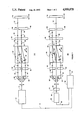
- FIG. 1 depicts in schematic form one embodiment of the instant invention where, for clarity, the figure is divided into parts (a) and (b) which show the beams in two different planes; and
- FIG. 2 depicts in schematic form the same embodiment as in FIG. 1, except in perspective view.
- FIG. 1 depicts, in schematic form, one embodiment of the instant invention. Because the optical beams lie in two distinct planes, the figure is divided into parts (a) and (b). While the apparatus has application for a wide range of radiation sources, the following description is taken by way of example with respect to an optical measuring system.
- light source (10) which most preferably uses a frequency stabilized laser, emits input beam (12) which is comprised of two linear, orthogonally polarized components as indicated by the dot and arrow, which may or may not be of the same optical frequency. If the frequencies are the same, see for example, Downs, et al., U.S. Pat. No. 4,360,271, issued Nov. 23, 1982.
- Beam (12) passes through holes in retroreflector (60) and quarter-wave phase retardation plate (62) and is incident on crystal (64).
- Crystal (64) is birefringent (e.g., quartz or calcite) with optical axis (65).
- the component of polarization perpendicular to the figure (indicated by the dot) is transmitted as beam (20) whereas the component of polarization parallel to the figure (indicated by the arrow) is transmitted at a slight angle as beam (21).
- Beam (20) leaves crystal (64) as beam (22).
- Beam (21) leaves crystal (64) as beam (23) which is now parallel to beam (22).
- Beams (22) and (23) pass through quarter-wave phase retardation plate (66) and are converted into circularly polarized beams (24) and (25), respectively.
- Beam (24) is reflected from stationary reference plane mirror (68) as beam (26) while beam (25) is reflected from movable plane mirror (70), affixed to the stage (not shown) whose relative position is being measured, as beam (27).
- Beams (26) and (27) pass through quarter-wave phase retardation plate (66) and are converted back into linearly polarized beams (28) and (29), respectively, which are orthogonally polarized to beams (22) and (23), respectively.
- Beam (29) is directly transmitted by crystal (64) as beam (31), while beam (28) is transmitted by crystal (64) at a slight angle as beam (30).
- Beam (31) leaves crystal (64) as beam (33).
- Beam (30) leaves crystal (64) as beam (32).
- Beams (32) and (33) pass through quarter-wave phase retardation plate (62) and are converted into circularly polarized beams (34) and (35), respectively.
- Beams (34) and (35) enter retroreflector (60) and are reflected as beams (36) and (37), respectively.
- Beams (36) and (37) travel through retroreflector (60) taking them to diametrically opposite positions as beams (38) and (39), respectively, as shown in part (b) of the figure.
- Beams (38) and (39) emerge from retroreflector (60) as beams (40) and (41), respectively.
- Beams (40) and (41) pass back through quarter-wave phase retardation plate (62) and are converted back into linearly polarized beams (42) and (43), respectively.
- Beam (42) is directly transmitted by crystal (64) as beam (44) while beam (43) is transmitted by crystal (64) at a slight angle as beam (45).
- Beam (44) leaves crystal (64) as beam (46).
- Beam (45) leaves crystal (64) as beam (47).
- Beams (46) and (47) pass through quarter-wave retardation plate (66) and are converted into circularly polarized beams (48) and (49), respectively.
- Beam (48) is reflected from stationary reference plane mirror (68) as beam (50) while beam (49) is reflected from movable plane mirror (70) as beam (51).
- Beams (50) and (51) pass back through quarter-wave phase retardation plate (66) and are converted back into linearly polarized beams (52) and (53), respectively, which are orthogonally polarized to beams (46) and (47), respectively.
- Beam (53) is directly transmitted by crystal (64) as beam (55) while beam (52) is transmitted by crystal (64) at a slight angle as beam (54). Beams (54) and (55) are recombined as beam (80) as they leave crystal (64).
- Beam (80) passes through the hole in quarter-wave phase retardation plate (62) and retroreflector (60).
- module (90) extracts the phase variation from electrical signal (85).
- module (90) does not require a reference signal (11) since there is no corresponding frequency difference, and conventionally extracts the phase variation from signal (85) such as in the manner described in U.S. Pat. No. 4,360,271.
- an additional sinusoidal electrical reference signal (11) equal in frequency to the difference between the two optical frequencies is preferably required by electronic module (90), which reference signal (11), as previously mentioned, would be provided from source (10) in which instance photodetector (83) would detect the interference between the two frequency components as a sinusoidal intensity variation with a frequency approximately equal to the difference frequency between the two components of beam (12), and module (90) would preferably comprise a phase meter/accumulator such as described in the aforementioned U.S. Pat. No. 4,688,940.
- electronic module (90) provides output (92) which is directly proportional to the change in optical path length between stationary reference plane mirror (68) and movable plane mirror (70), thus providing a measurement of optical path length change between the two plane mirror surfaces (68, 70).
- This optical configuration reduces measurement errors, due to polarization mixing between the reference and measurement beams within the interferometer, by several orders of magnitude because crystal (64) has superior polarization characteristics as compared to those of a polarization beamsplitter typically used in displacement interferometers. Furthermore, this optical configuration is extremely insensitive to measurement error because changes in the other optical components, such as those induced mechanically or thermally, affect both polarization components equally and therefore have no influence on the measured phase variation (92).
- FIG. 2 depicts in schematic form the same embodiment of the instant invention, except shown in perspective view.
- Light source (10) emits beam (12) which is comprised of two linear, orthogonally polarized components as indicated by the two arrows, which may or may not be of the same optical frequency.
- Beam (12) enters interferometer body (69) which consist of retroflector (60), quarter-wave phase retardation plates (62) and (66) and crystal (64).
- beams (24) and (25) emerge and are reflected from stationary reference mirror (68) and movable plane mirror (70), respectively, as beam (26) and (27) respectively.
- Beams (26) and (27) re-enter interferometer body (69) and, as described previously, emerge as beams (48) and (49).
- Beam (48) and (49) are reflected from stationary reference plane mirror (68) and movable plane mirror (70), respectively, as beams (50) and (51), respectively. Beams (50) and (51) re-enter interferometer body (69) and, as described previously, are combined and emerge as beam (80).
- module (90) extracts the phase variation from electrical signal (85).
- module (90) does not require reference signal (11) since there is no corresponding frequency difference, and conventionally extracts the phase variation from signal (85) such as in the manner described in U.S. Pat. No. 4,360,271.
- an additional sinusoidal electrical reference signal (11) equal in frequency to the difference between the two optical frequencies is preferably required by electronic module (90), which reference signal (11) as previously mentioned, would be provided from source (10) in which instance photodetector (83) would detect the interference between the two frequency components as a sinusoidal intensity variation with a frequency approximately equal to the difference frequency between the two components of beam (12), and module (90) would preferably comprise a phase meter/accumulator such as described in the aforementioned U.S. Pat. No. 4,688,940.
- electronic module (90) provides output (92) which is directly proportional to the charge in optical path length between stationary reference plane mirror (68) and movable plane mirror (70).
- the principal advantage of the instant invention is: (1) significantly reduced cyclic non-linearity errors.
Abstract
Description
Claims (35)
Priority Applications (1)
| Application Number | Priority Date | Filing Date | Title |
|---|---|---|---|
| US07/282,018 US4950078A (en) | 1988-12-08 | 1988-12-08 | High accuracy differential plane mirror interferometer |
Applications Claiming Priority (1)
| Application Number | Priority Date | Filing Date | Title |
|---|---|---|---|
| US07/282,018 US4950078A (en) | 1988-12-08 | 1988-12-08 | High accuracy differential plane mirror interferometer |
Publications (1)
| Publication Number | Publication Date |
|---|---|
| US4950078A true US4950078A (en) | 1990-08-21 |
Family
ID=23079742
Family Applications (1)
| Application Number | Title | Priority Date | Filing Date |
|---|---|---|---|
| US07/282,018 Expired - Lifetime US4950078A (en) | 1988-12-08 | 1988-12-08 | High accuracy differential plane mirror interferometer |
Country Status (1)
| Country | Link |
|---|---|
| US (1) | US4950078A (en) |
Cited By (18)
| Publication number | Priority date | Publication date | Assignee | Title |
|---|---|---|---|---|
| EP0444526A2 (en) * | 1990-03-01 | 1991-09-04 | Dr. Johannes Heidenhain GmbH | Optical device |
| US5133599A (en) * | 1991-01-02 | 1992-07-28 | Zygo Corporation | High accuracy linear displacement interferometer with probe |
| US5289434A (en) * | 1992-09-18 | 1994-02-22 | Shell Oil Company | Retroreflector apparatus for remote seismic sensing |
| US5317383A (en) * | 1992-09-18 | 1994-05-31 | Shell Oil Company | Array retroreflector apparatus for remote seismic sensing |
| US5325175A (en) * | 1992-05-08 | 1994-06-28 | Honeywell Inc. | Solid-block homodyne interferometer |
| US5327216A (en) * | 1992-09-18 | 1994-07-05 | Shell Oil Company | Apparatus for remote seismic sensing of array signals using side-by-side retroreflectors |
| US5404222A (en) * | 1994-01-14 | 1995-04-04 | Sparta, Inc. | Interferametric measuring system with air turbulence compensation |
| US5648848A (en) * | 1995-02-01 | 1997-07-15 | Nikon Precision, Inc. | Beam delivery apparatus and method for interferometry using rotatable polarization chucks |
| EP0795116A1 (en) * | 1994-11-28 | 1997-09-17 | The Regents Of The University Of California | Phase shifting diffraction interferometer |
| US5991033A (en) * | 1996-09-20 | 1999-11-23 | Sparta, Inc. | Interferometer with air turbulence compensation |
| US6243200B1 (en) * | 2000-03-02 | 2001-06-05 | Chorum Technologies, Inc. | Optical wavelength router based on polarization interferometer |
| WO2001084200A2 (en) * | 2000-05-01 | 2001-11-08 | Chorum Technologies Lp | Optical wdm device having polarization elements |
| US6498680B1 (en) | 1996-10-29 | 2002-12-24 | Chorum Technologies Lp | Compact tunable optical wavelength interleaver |
| US6674521B1 (en) * | 2000-05-12 | 2004-01-06 | The Regents Of The University Of Michigan | Optical method and system for rapidly measuring relative angular alignment of flat surfaces |
| US6717678B2 (en) * | 2000-12-08 | 2004-04-06 | Zygo Corporation | Monolithic corrector plate |
| US20050195404A1 (en) * | 2004-03-03 | 2005-09-08 | Carlson Andrew E. | Interferometers and systems using interferometers |
| US20060098205A1 (en) * | 2004-11-09 | 2006-05-11 | Townley-Smith Paul A | Optical connection for interferometry |
| US7298493B2 (en) | 2004-06-30 | 2007-11-20 | Zygo Corporation | Interferometric optical assemblies and systems including interferometric optical assemblies |
Citations (2)
| Publication number | Priority date | Publication date | Assignee | Title |
|---|---|---|---|---|
| US3976379A (en) * | 1972-12-28 | 1976-08-24 | Olympus Optical Co., Ltd. | Interferometers |
| US4693605A (en) * | 1985-12-19 | 1987-09-15 | Zygo Corporation | Differential plane mirror interferometer |
-
1988
- 1988-12-08 US US07/282,018 patent/US4950078A/en not_active Expired - Lifetime
Patent Citations (2)
| Publication number | Priority date | Publication date | Assignee | Title |
|---|---|---|---|---|
| US3976379A (en) * | 1972-12-28 | 1976-08-24 | Olympus Optical Co., Ltd. | Interferometers |
| US4693605A (en) * | 1985-12-19 | 1987-09-15 | Zygo Corporation | Differential plane mirror interferometer |
Cited By (26)
| Publication number | Priority date | Publication date | Assignee | Title |
|---|---|---|---|---|
| EP0444526A3 (en) * | 1990-03-01 | 1992-05-27 | Dr. Johannes Heidenhain Gmbh | Optical device |
| EP0444526A2 (en) * | 1990-03-01 | 1991-09-04 | Dr. Johannes Heidenhain GmbH | Optical device |
| US5133599A (en) * | 1991-01-02 | 1992-07-28 | Zygo Corporation | High accuracy linear displacement interferometer with probe |
| US5325175A (en) * | 1992-05-08 | 1994-06-28 | Honeywell Inc. | Solid-block homodyne interferometer |
| US5327216A (en) * | 1992-09-18 | 1994-07-05 | Shell Oil Company | Apparatus for remote seismic sensing of array signals using side-by-side retroreflectors |
| US5317383A (en) * | 1992-09-18 | 1994-05-31 | Shell Oil Company | Array retroreflector apparatus for remote seismic sensing |
| US5289434A (en) * | 1992-09-18 | 1994-02-22 | Shell Oil Company | Retroreflector apparatus for remote seismic sensing |
| US5404222A (en) * | 1994-01-14 | 1995-04-04 | Sparta, Inc. | Interferametric measuring system with air turbulence compensation |
| US5537209A (en) * | 1994-01-14 | 1996-07-16 | Sparta, Inc. | An interferometric measuring system having temperature compensation and improved optical configurations |
| US5543914A (en) * | 1994-01-14 | 1996-08-06 | Sparta, Inc. | Apparatus and methods employing harmonic analysis for measuring the difference in phase between two coherent beams |
| EP0795116A4 (en) * | 1994-11-28 | 2000-01-12 | Univ California | Phase shifting diffraction interferometer |
| EP0795116A1 (en) * | 1994-11-28 | 1997-09-17 | The Regents Of The University Of California | Phase shifting diffraction interferometer |
| US5648848A (en) * | 1995-02-01 | 1997-07-15 | Nikon Precision, Inc. | Beam delivery apparatus and method for interferometry using rotatable polarization chucks |
| US5991033A (en) * | 1996-09-20 | 1999-11-23 | Sparta, Inc. | Interferometer with air turbulence compensation |
| US6498680B1 (en) | 1996-10-29 | 2002-12-24 | Chorum Technologies Lp | Compact tunable optical wavelength interleaver |
| US6243200B1 (en) * | 2000-03-02 | 2001-06-05 | Chorum Technologies, Inc. | Optical wavelength router based on polarization interferometer |
| US6455841B2 (en) * | 2000-03-02 | 2002-09-24 | Chorum Technologies Lp | Optical wavelength router based on polarization interferometer |
| WO2001084200A2 (en) * | 2000-05-01 | 2001-11-08 | Chorum Technologies Lp | Optical wdm device having polarization elements |
| WO2001084200A3 (en) * | 2000-05-01 | 2002-06-13 | Chorum Technologies Lp | Optical wdm device having polarization elements |
| US6674521B1 (en) * | 2000-05-12 | 2004-01-06 | The Regents Of The University Of Michigan | Optical method and system for rapidly measuring relative angular alignment of flat surfaces |
| US6717678B2 (en) * | 2000-12-08 | 2004-04-06 | Zygo Corporation | Monolithic corrector plate |
| US20050195404A1 (en) * | 2004-03-03 | 2005-09-08 | Carlson Andrew E. | Interferometers and systems using interferometers |
| US7310152B2 (en) | 2004-03-03 | 2007-12-18 | Zygo Corporation | Interferometer assemblies having reduced cyclic errors and system using the interferometer assemblies |
| US7298493B2 (en) | 2004-06-30 | 2007-11-20 | Zygo Corporation | Interferometric optical assemblies and systems including interferometric optical assemblies |
| US20060098205A1 (en) * | 2004-11-09 | 2006-05-11 | Townley-Smith Paul A | Optical connection for interferometry |
| US7277180B2 (en) * | 2004-11-09 | 2007-10-02 | Zygo Corporation | Optical connection for interferometry |
Similar Documents
| Publication | Publication Date | Title |
|---|---|---|
| US4802765A (en) | Differential plane mirror having beamsplitter/beam folder assembly | |
| US4693605A (en) | Differential plane mirror interferometer | |
| US4950078A (en) | High accuracy differential plane mirror interferometer | |
| US4881816A (en) | Linear and angular displacement measuring interferometer | |
| US4883357A (en) | Dual high stability interferometer | |
| US4752133A (en) | Differential plane mirror interferometer | |
| US4859066A (en) | Linear and angular displacement measuring interferometer | |
| US4746216A (en) | Angle measuring interferometer | |
| KR100322938B1 (en) | Superheterodyne interferometry and method for compensating the refractive index of air using electronic frequency multiplication | |
| US4881815A (en) | Linear and angular displacement measuring interferometer | |
| EP0281385B1 (en) | Plane mirror interferometer | |
| US5764362A (en) | Superheterodyne method and apparatus for measuring the refractive index of air using multiple-pass interferometry | |
| US4685803A (en) | Method and apparatus for the measurement of the refractive index of a gas | |
| US4733967A (en) | Apparatus for the measurement of the refractive index of a gas | |
| Yacoot et al. | The use of x-ray interferometry to investigate the linearity of the NPL differential plane mirror optical interferometer | |
| US4717250A (en) | Angle measuring interferometer | |
| US4802764A (en) | Differential plane mirror interferometer having beamsplitter/beam folder assembly | |
| US5546184A (en) | Single-frequency bidirectional fringe-counting interferometer | |
| US4787747A (en) | Straightness of travel interferometer | |
| US5133599A (en) | High accuracy linear displacement interferometer with probe | |
| US4711574A (en) | Minimum deadpath interferometer and dilatometer | |
| US4930894A (en) | Minimum deadpath interferometer and dilatometer | |
| Downs et al. | Bi-directional fringe counting interference refractometer | |
| US4807997A (en) | Angular displacement measuring interferometer | |
| EP0239506A2 (en) | Differential plane mirror interferometer |
Legal Events
| Date | Code | Title | Description |
|---|---|---|---|
| AS | Assignment |
Owner name: ZYGO CORPORATION, MIDDLEFIELD, CT 06455, A CORP. O Free format text: ASSIGNMENT OF ASSIGNORS INTEREST.;ASSIGNOR:SOMMARGREN, GARY E.;REEL/FRAME:004986/0180 Effective date: 19880930 Owner name: ZYGO CORPORATION, A CORP. OF DE, CONNECTICUT Free format text: ASSIGNMENT OF ASSIGNORS INTEREST;ASSIGNOR:SOMMARGREN, GARY E.;REEL/FRAME:004986/0180 Effective date: 19880930 |
|
| STCF | Information on status: patent grant |
Free format text: PATENTED CASE |
|
| CC | Certificate of correction | ||
| FPAY | Fee payment |
Year of fee payment: 4 |
|
| FPAY | Fee payment |
Year of fee payment: 8 |
|
| FEPP | Fee payment procedure |
Free format text: PAYOR NUMBER ASSIGNED (ORIGINAL EVENT CODE: ASPN); ENTITY STATUS OF PATENT OWNER: LARGE ENTITY |
|
| FPAY | Fee payment |
Year of fee payment: 12 |
|
| REMI | Maintenance fee reminder mailed |