US4953583A - Tank pressure control valve - Google Patents
Tank pressure control valve Download PDFInfo
- Publication number
- US4953583A US4953583A US07/328,451 US32845189A US4953583A US 4953583 A US4953583 A US 4953583A US 32845189 A US32845189 A US 32845189A US 4953583 A US4953583 A US 4953583A
- Authority
- US
- United States
- Prior art keywords
- fuel vapor
- blocking
- flow
- fuel
- fuel tank
- Prior art date
- Legal status (The legal status is an assumption and is not a legal conclusion. Google has not performed a legal analysis and makes no representation as to the accuracy of the status listed.)
- Expired - Fee Related
Links
Images


Classifications
-
- F—MECHANICAL ENGINEERING; LIGHTING; HEATING; WEAPONS; BLASTING
- F16—ENGINEERING ELEMENTS AND UNITS; GENERAL MEASURES FOR PRODUCING AND MAINTAINING EFFECTIVE FUNCTIONING OF MACHINES OR INSTALLATIONS; THERMAL INSULATION IN GENERAL
- F16K—VALVES; TAPS; COCKS; ACTUATING-FLOATS; DEVICES FOR VENTING OR AERATING
- F16K31/00—Actuating devices; Operating means; Releasing devices
- F16K31/12—Actuating devices; Operating means; Releasing devices actuated by fluid
- F16K31/36—Actuating devices; Operating means; Releasing devices actuated by fluid in which fluid from the circuit is constantly supplied to the fluid motor
- F16K31/365—Actuating devices; Operating means; Releasing devices actuated by fluid in which fluid from the circuit is constantly supplied to the fluid motor the fluid acting on a diaphragm
-
- B—PERFORMING OPERATIONS; TRANSPORTING
- B60—VEHICLES IN GENERAL
- B60K—ARRANGEMENT OR MOUNTING OF PROPULSION UNITS OR OF TRANSMISSIONS IN VEHICLES; ARRANGEMENT OR MOUNTING OF PLURAL DIVERSE PRIME-MOVERS IN VEHICLES; AUXILIARY DRIVES FOR VEHICLES; INSTRUMENTATION OR DASHBOARDS FOR VEHICLES; ARRANGEMENTS IN CONNECTION WITH COOLING, AIR INTAKE, GAS EXHAUST OR FUEL SUPPLY OF PROPULSION UNITS IN VEHICLES
- B60K15/00—Arrangement in connection with fuel supply of combustion engines or other fuel consuming energy converters, e.g. fuel cells; Mounting or construction of fuel tanks
- B60K15/03—Fuel tanks
- B60K15/035—Fuel tanks characterised by venting means
- B60K15/03519—Valve arrangements in the vent line
-
- B—PERFORMING OPERATIONS; TRANSPORTING
- B60—VEHICLES IN GENERAL
- B60K—ARRANGEMENT OR MOUNTING OF PROPULSION UNITS OR OF TRANSMISSIONS IN VEHICLES; ARRANGEMENT OR MOUNTING OF PLURAL DIVERSE PRIME-MOVERS IN VEHICLES; AUXILIARY DRIVES FOR VEHICLES; INSTRUMENTATION OR DASHBOARDS FOR VEHICLES; ARRANGEMENTS IN CONNECTION WITH COOLING, AIR INTAKE, GAS EXHAUST OR FUEL SUPPLY OF PROPULSION UNITS IN VEHICLES
- B60K15/00—Arrangement in connection with fuel supply of combustion engines or other fuel consuming energy converters, e.g. fuel cells; Mounting or construction of fuel tanks
- B60K15/03—Fuel tanks
- B60K15/035—Fuel tanks characterised by venting means
- B60K2015/03561—Venting means working at specific times
- B60K2015/03576—Venting during filling the reservoir
-
- Y—GENERAL TAGGING OF NEW TECHNOLOGICAL DEVELOPMENTS; GENERAL TAGGING OF CROSS-SECTIONAL TECHNOLOGIES SPANNING OVER SEVERAL SECTIONS OF THE IPC; TECHNICAL SUBJECTS COVERED BY FORMER USPC CROSS-REFERENCE ART COLLECTIONS [XRACs] AND DIGESTS
- Y10—TECHNICAL SUBJECTS COVERED BY FORMER USPC
- Y10T—TECHNICAL SUBJECTS COVERED BY FORMER US CLASSIFICATION
- Y10T137/00—Fluid handling
- Y10T137/2496—Self-proportioning or correlating systems
- Y10T137/2559—Self-controlled branched flow systems
- Y10T137/265—Plural outflows
- Y10T137/2652—Single actuator operates plural outlets simultaneously
-
- Y—GENERAL TAGGING OF NEW TECHNOLOGICAL DEVELOPMENTS; GENERAL TAGGING OF CROSS-SECTIONAL TECHNOLOGIES SPANNING OVER SEVERAL SECTIONS OF THE IPC; TECHNICAL SUBJECTS COVERED BY FORMER USPC CROSS-REFERENCE ART COLLECTIONS [XRACs] AND DIGESTS
- Y10—TECHNICAL SUBJECTS COVERED BY FORMER USPC
- Y10T—TECHNICAL SUBJECTS COVERED BY FORMER US CLASSIFICATION
- Y10T137/00—Fluid handling
- Y10T137/7722—Line condition change responsive valves
- Y10T137/7771—Bi-directional flow valves
- Y10T137/778—Axes of ports co-axial
-
- Y—GENERAL TAGGING OF NEW TECHNOLOGICAL DEVELOPMENTS; GENERAL TAGGING OF CROSS-SECTIONAL TECHNOLOGIES SPANNING OVER SEVERAL SECTIONS OF THE IPC; TECHNICAL SUBJECTS COVERED BY FORMER USPC CROSS-REFERENCE ART COLLECTIONS [XRACs] AND DIGESTS
- Y10—TECHNICAL SUBJECTS COVERED BY FORMER USPC
- Y10T—TECHNICAL SUBJECTS COVERED BY FORMER US CLASSIFICATION
- Y10T137/00—Fluid handling
- Y10T137/8593—Systems
- Y10T137/86292—System with plural openings, one a gas vent or access opening
- Y10T137/86324—Tank with gas vent and inlet or outlet
Definitions
- the present invention relates to pressure control valves for selectively discharging fuel vapor pressure from a fuel tank during refueling and introducing air into the fuel tank in response to development of vacuum conditions therein. More particularly, the present invention relates to a stageable tank pressure control valve having a primary stage system for venting the fuel tank to a first destination and an optional auxiliary stage system for venting the fuel tank to a second destination.
- New fuel vapors are generated during refueling due to splash and agitation of the dispensed fuel, as well as from potential temperature differences between the fuel tank and the dispensed fuel.
- fuel vapors that are present in the tank and generated during refueling are displaced by liquid fuel. These displaced fuel vapors are moved out of the fuel tank vapor space by the displacing action of the liquid fuel. In many conventional vehicle fuel systems, these displaced vapors are released directly into the atmosphere via the fuel tank filler neck and are a contributing factor to air pollution.
- One object of the present invention is to provide a tank pressure control valve of small size and economical construction that nevertheless is configured to discharge a substantial volume and mass of pressurized fuel vapor from a fuel tank using a minimum of moving parts during development of high vapor pressure in the tank such as occurs during refueling or the like.
- Another object of the present invention is to provide a tank pressure control valve having at least two tank venting stages so that one venting path is established between the fuel tank and a first destination (e.g., a vapor treatment site) upon development of a first pressure magnitude in the tank, and another venting path is established between the fuel tank and a second destination (e.g., an auxiliary fuel vapor treatment site) upon further development of a greater second pressure magnitude in the tank.
- a first destination e.g., a vapor treatment site
- a second destination e.g., an auxiliary fuel vapor treatment site
- Yet another object of the present invention is to provide a tank pressure-relief control valve that is configured to close automatically following conclusion of a vehicle refueling activity, yet is also configured to function as a vacuum-relief valve in response to development of subatmospheric pressure in the fuel tank.
- an apparatus for controlling discharge of fuel vapors from a fuel tank during refueling.
- the apparatus includes means for conducting fuel vapor between the fuel tank and a fuel vapor treatment site situated outside of the fuel tank, means for selectively blocking flow of fuel vapor through the conducting means, and biasing means.
- the blocking means is operable between a flow-blocking position and a flow-delivery position.
- the biasing means acts to yieldably bias the blocking means toward its flow-blocking position.
- Means is further provided for receiving and using fuel vapor pressure from the fuel tank having a magnitude in excess of a predetermined threshold level to exert an opening force on the blocking means in opposition to the biasinq means.
- the usinq means defines a venting control chamber in communication with the blocking means. In operation, the blocking means is moved to its flow-delivery position because of containment of fuel vapor pressure in the venting control chamber, thereby permitting discharge of pressurized fuel vapor in the tank to said fuel vapor treatment site through the conducting means.
- the venting control chamber is situated outside of the fuel tank and the blocking means extends through the conducting means into the fuel tank and includes means for communicating fuel vapor from the fuel tank to the venting control chamber.
- the conducting means includes a partition formed to include a venting aperture interconnecting the fuel tank and fuel vapor treatment site in fluid communication.
- the blocking means further includes an elongated stem having a valve member affixed at one end and a support member affixed at the other end. The valve member is formed to include a central aperture communicating with the fuel tank and the support member is formed to include a central aperture.
- the using means includes first and second walls sealably coupled together to define the venting control chamber. Also, the first and second walls are movable relative to one another to permit expansion and contraction of the volume of the venting control chamber.
- the support member forms a portion of the second wall.
- the biasing means is situated to act between the partition and the support member normally to urge the valve member against the partition closing the venting aperture.
- the stem is hollow to provide a pressure transmission passage interconnecting the central apertures of the valve member and the support member and terminating in the venting control chamber to define the communicating means.
- systems are provided for moving the valve member to its closed position at the conclusion of a refueling activity.
- Means is provided in the fuel tank for blocking introduction of pressurized fuel vapor in the fuel tank into the communicating means to prevent communication of pressurized fuel vapor to the venting control chamber in response to accumulation of fuel in the fuel tank in excess of a predetermined volume.
- This level-sensing means acts to shut off supply of pressurized fuel vapor to the venting control chamber through the communicating means.
- Means is also provided for bleeding pressurized fuel vapor from the venting control chamber at a predetermined rate to permit the biasing means to move the support member and the second wall relative to the first wall, thereby contracting the volume of the venting control chamber and urging the venting valve member toward its flow-blocking position.
- a stageable tank pressure control valve further includes means for communicating fuel vapor from the conducting means to at least one of the atmosphere and another fuel vapor treatment site, valve means for selectively blocking flow of fuel vapor through the communicating means, and auxiliary biasing means for yieldably biasing the valve means toward its flow-blocking position.
- the valve means is operable between a flow-blocking position and flow-delivery positions.
- control means communicating with the venting control chamber is provided for using fuel vapor pressure in the fuel tank having a magnitude in excess of a greater second predetermined threshold level to exert an opening force on the valve means so that the valve means is moved in opposition to the auxiliary biasing means to its flow-delivery position.
- Such movement of the valve member permits discharge of pressurized fuel vapor in the tank to another destination such as a fuel vapor treatment site through the conducting means and the communicating means.
- One feature of the present invention is the provision of means for using fuel vapor pressure from the fuel tank in a venting control chamber to control the actuation of flow-blocking means to regulate the flow of fuel vapor into and out of the fuel tank.
- the blocking means is acted upon by a force generated by fuel vapor pressure in the venting control chamber to move the blocking means from its normal flow-blocking position to its flow-delivery position.
- the magnitude of the actuation force applied to the blocking means by fuel vapor pressure in the venting control chamber is not affected by the size of the venting aperture closable by the blocking means.
- the size of the venting aperture can be enlarged to increase the discharge capacity of the venting assembly without sacrificing reliability or increasing the overall size of the assembly.
- Another feature of the present invention is the provision of a two-stage tank pressure control valve having control means communicating with the venting control chamber for using fuel vapor pressure to open an auxiliary valve.
- the control valve is set up to open the auxiliary valve whenever the pressure in the venting control chamber rises above the actuation pressure of the blocking means to a second greater pressure.
- the auxiliary valve can be used to discharge excess fuel vapor to a second destination (e.g., another fuel vapor treatment site) to avoid overloading the capacity of the canister connectable to the fuel tank by actuation of the blocking means.
- FIG. 1 is a sectional view of an embodiment of a single-stage valve assembly in accordance with the present invention showing blocking means of the assembly in its flow-blocking position;
- FIG. 2 is a view of the valve assembly shown in FIG. 1 showing the blocking means in its flow-delivery position;
- FIG. 3 is a view of the valve assembly shown in FIG. 1 showing bleeding of pressure in the venting control chamber upon cessation of the supply of pressurized fuel vapor from the fuel tank to the venting control chamber;
- FIG. 4 is a view of the valve assembly shown in FIG. 1 showing the position of the blocking means in response to development of subatmospheric pressure in the fuel tank;
- FIG. 5 is a sectional view of an embodiment of a two-stage valve assembly in accordance with the present invention showing each of the first- and second-stage valves in its flow-blocking position;
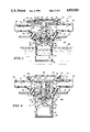
- FIG. 6 is a view of the valve assembly shown in FIG. 5 showing the first-stage valve in its flow-delivery position to vent tank pressure to a first destination and the second-stage valve in its flow-blocking position;
- FIG. 7 is a view of the valve assembly shown in FIG. 5 showing both first- and second-stage valves in their flow-delivering positions to vent tank pressure to two separate destinations;
- FIG. 8 is a view of the valve assembly shown in FIG. 5 showing bleeding of pressure in the venting control chamber upon cessation of the supply of pressurized fuel vapor from the fuel tank to the venting control chamber.
- FIGS. 1-4 A first embodiment of the invention is illustrated in FIGS. 1-4.
- a valve assembly 10 is provided for use with a conventional fuel system (not shown) having a fuel tank and at least one fuel vapor storage canister.
- a hollow vent housing 12 is mounted in the outlet 14 formed in the top wall 16 of a fuel tank 18 as shown in FIG. 1.
- Gasket 20 seals the joint between top wall 16 and the portion of housing 12 bordering outlet 14 to prevent the escape of fuel vapor therethrough.
- a partition 21 extends into the interior of the housing 12 to divide the housing 12 into inner and outer chambers 22 and 24.
- Housing 12 is mounted in outlet 14 to position the inner chamber 22 substantially within the vapor space 26 of the fuel tank 18 and to position the outer chamber 24 on the other side of the top wall 16 of tank 18.
- Partition 21 includes an annular radially inwardly facing surface 28 defining a venting aperture 30 and an axially inwardly facing surface 32 providing a valve seat in the inner chamber 22. Venting aperture 30 interconnects the inner and outer chambers 22 and 24 in fluid communication and provides a first fuel vapor flow port for conducting fuel vapor between chambers 22 and 24.
- Inner chamber 22 is defined by a lower side wall 34 of housing 12.
- Side wall 34 is formed to include aperture means 36 near partition 21 for interconnecting inner chamber 22 and vapor space 26 in fluid communication.
- Valve guide 38 is attached to surface 32 of partition 21 and extends in an axially inward direction as shown in FIG. 1 in radially outwardly spaced direction relative to venting aperture 30.
- Hollow float member 40 is positioned in inner chamber 22 as shown in FIG. 1.
- Float member 40 is cup-shaped and includes a side wall 42 contoured to terminate at a valve stem 44 having a distal spherical end 46.
- Float member 40 is hollowed or otherwise configured to be supported buoyantly in liquid fuel 48 in the fuel tank 18 upon accumulation of a sufficient volume of fuel as illustrated in FIG. 3.
- An end cap 50 is ring-shaped and coupled to the axially innermost end of side wall 42 to retain float member 40 within inner chamber 22.
- Outer chamber 24 is defined in part by upper housing portion 52 of housing 12 which extends in an axially outward direction from partition 21 and is formed to include an annular top wall 54 having an annular radially inwardly facing edge 56 which defines a top opening.
- Upper housing portion 52 also includes a first discharge outlet 58 formed to include a first passageway 60 for conducting fuel vapor from the outer chamber 24 to a first fuel vapor treatment site (not shown).
- upper housing portion 52 further includes a second discharge outlet 62 formed to include a second passageway 64 for conducting fuel vapor from the outer chamber 24 to a second destination such as a second fuel vapor treatment site.
- Venting valve member 66 is formed of a resilient sealing material and positioned in inner chamber 22 for movement toward and away from engagement with valve seat 32. Venting valve member 66 is ring-shaped and mounted on the top surface of annular valve support pad 68. A cylindrically shaped hollow stem 70 extends through venting aperture 30 and has an axially inner end connected to valve support pad 68. The diameter of stem 70 is selected so that the exterior surface 72 of stem 70 lies in spaced-apart relation to annular radially inwardly facing surface 28 to define an annular venting space therebetween through which fuel vapor can be conducted between the inner and outer chambers 22 and 24 upon movement of venting valve member 66 away from valve seat 32 to a flow-delivering position. As shown in FIG. 1, valve member 66 is ring-shaped so that a radially inwardly facing edge abuts the exterior surface 72 of stem 70 adjacent the connection between the stem 70 and the valve support pad 68.
- Stem 70 is configured and positioned to assist in actuating valve member 66 and thus will henceforth be referred to as the actuator stem 70.
- actuator stem 70 is hollowed to provide an inlet 74 at its axially inner end for admitting pressurized fuel vapor from the vapor space 26, an outlet 76 at its axially outer end for discharging fuel vapor into a venting control chamber 78, and a pressure transmission passage 80 extending therebetween.
- Inlet 74 provides a second fuel vapor flow port for conducting fuel vapor between chambers 22 and 24.
- Actuator stem 78 is also formed to include an axially downwardly facing, generally conical valve seat 82 in concentric registry with inlet 74.
- the distal spherical end 46 of valve stem 44 is configured to seal against the conical valve seat 82 upon flotation of float member 40 to its raised floating position illustrated in FIG. 3.
- a barrier assembly is positioned in the outer chamber 24 near the top opening 56 of the upper housing portion 52 to interconnect the annular top wall 54 to the axially outer end of the actuator stem 78 to define a sealed boundary wall between the outer chamber 24 and the venting control chamber 78.
- the barrier member assembly includes a flexible diaphragm 84, an annular support 86, and an annular actuation pad 88.
- Diaphragm 84 includes a mounting rim 90 contacting top wall 52, an actuation member 92, and an annular sealing web 94 interconnecting mounting rim 90 and actuation member 92.
- Actuation member 92 is sandwiched between the annular support member 86 and annular actuation pad 88 to form a ring-like assembly affixed to the axially outer end of actuator stem 70 as shown in FIG. 1.
- Each of support member 86, actuation pad 88, and actuation member 92 are formed to include a central aperture which is aligned in concentric registry with the outlet 76 of hollow actuator stem 70 as seen in FIG. 1.
- pressurized fuel vapor in the vapor space 26 of fuel tank 18 is communicable to venting control chamber 78 via pressure transmission passage 80.
- a control chamber cover 96 is affixed to top wall 52 so that its interior wall 98 is presented toward the radially inwardly situated actuation pad 92 and the radially outwardly situated sealing web 94.
- the outer rim 100 of cover 96 urges mounting rim 90 against top wall 52 to establish a circumferentially extending vapor seal which acts to prevent pressurized fuel vapor in venting control chamber 78 from seeping into the outer chamber 24.
- interior wall 98 of cover 96 provides a first boundary wall and the axially outwardly facing surface of sealing web 94, actuation member 92, and actuation pad 99 provide a second boundary wall, which first and second boundary walls cooperate to define the venting control chamber 78.
- the volume of chamber 78 is expandable and contractible because the flexible, resilient character of sealing web 94 permits movement of the actuation member 92, actuation pad 92, support member 86, and actuator stem 70 relative to the interior wall 98 of the control chamber cover 96.
- a coiled compression spring 110 is positioned in outer chamber 24 and acts between the axially inwardly facing surface of annular support member 86 and an axially outwardly facing surface 112 of partition 21. Under normal low tank pressure conditions, spring 110 urges venting valve member 66 against valve seat 32 to close the venting space in venting aperture 30 between annular radially inwardly facing surface 28 and exterior surface 72 of actuator stem 70. Simultaneously, spring 110 urges support member 86 and the rest of the barrier assembly toward the control chamber cover 96 to contact the volume of the venting control chamber 78 as shown in FIG. 1. Further, an upstanding spring guard 114 is affixed to surface 112 and extends in an axially outward direction as shown in FIG. 1 to improve assembly and operation of spring 110.
- Ball valve 116 is loosely positioned in pressure transmission passage 80 as shown in FIG. 1. Normally, ball valve 116 rests against an axially upwardly facing, generally conical valve seat 118 in concentric registry with inlet 74 t block flow of fuel vapor pressure into pressure transmission passage 80. However, the mass and the size of the ball valve 116 are carefully selected so that pressure in inlet 74 will act to lift ball valve 116 away from seat 118 whenever the head pressure in the vapor space 26 is in excess of a predetermined threshold level such as a head pressure of about four to ten inches of water. Thus, ball valve 116 acts to limit entry of pressurized fuel vapor into the venting control chamber 78 until pressure in fuel tank 18 rises to at least a minimum level.
- Means is also provided for controllably discharging discharging fuel vapor from the venting control chamber 78 to reduce the magnitude of pressure therein under certain conditions.
- the actuator stem 70 is formed to include bleed aperture 120 which functions to provide means for "bleeding" pressure from the venting control chamber 78 to the outer chamber 24 at a predetermined rate, causing the magnitude of pressure in the venting control chamber 78 progressively to decrease upon engagement of the distal spherical end 46 of valve stem 44 against conical valve seat 82.
- the size of bleed aperture 120 is not large enough to affect normal expansion of the venting control chamber 78 substantially during introduction of pressurized fuel vapor into chamber 78 through pressure transmission passage 80.
- valve assembly 10 A sequence of operation of valve assembly 10 is illustrated in FIGS. 1-3 and an alternative function of valve 66 is illustrated in FIG. 4.
- spring 110 normally acts to urge valve 66 to its flow-blocking position against valve seat 32 so that no fuel vapor is conducted from vapor space 26 to either of the first and second fluid-conducting passageways 60 and 64 through the inner and outer chambers 22 and 24.
- fuel vapor from the tank 18 is not vented through valve assembly 10 to one of the vapor storage canisters (not shown) coupled to passageways 60 and 64.
- ball valve 116 closes pressure transmission passageway 80 to prevent premature expansion of the volume in venting control chamber 78 and actuation of venting control valve 66.
- Actuation of the venting control valve is illustrated in FIG. 2.
- Ball valve 116 is moved away from conical valve seat 118 as soon as pressure in the inlet 74 rises sufficiently to apply a lifting force to ball valve 116. Then, pressure generated by fuel vapor in the tank 18 during, for example, refueling of tank 18, will be transmitted to the venting control chamber 78. Once the magnitude of this pressure rises above a predetermined threshold level, it will act to apply an "actuation force" to at least actuation pad 88 sufficient to cause support member 86 to move against the opposing force provided by spring 110 and move the actuator stem 70 in an axially inward direction through venting aperture 30. This causes the venting valve member 66 to move away from valve seat 32 to a flow-delivery position, allowing pressurized fuel vapor in the tank 18 to vent on a fuel vapor storage canister (not shown) through valve assembly 10.
- One notable advantage of the present invention is that much better control over the actuation of valve 66 can be achieved easily by enlarging the "surface area" of the actuation pad 88 exposed to pressure in the venting control chamber 78.
- the magnitude of "actuation force” described above is a function of the pressure in venting control chamber 78 which acts on the above-noted "surface area.” It has been observed that one problem frequently encountered in high-volume manufacturing is production of a multiplicity of valves wherein each actuable valve is consistently actuated in use in response to the exact same set of inputs.
- valve actuation "sensitivity" problems of the type described can be minimized by using pressure in a control chamber separate from the fuel tank and also by enlarging the surface area of the valve portion exposed to pressure in the separate control chamber.
- this type of valve actuation system is easily incorporated into a compact structure to save valuable space and at low cost.
- valve 40 moves in FIG. 3.
- Float valve 40 rises in inner chamber 22 to close inlet 74 in actuator stem 70 in response to accumulation of liquid fuel in tank 18 in excess of a predetermined volume.
- Such closure is necessary to prevent discharge of liquid fuel to the canisters (not shown) and also to raise the pressure within tank 18 near the end of a refueling activity sufficiently to actuate the shut-off assembly in a fuel-dispensing nozzle (not shown) communicating with the tank 18.
- valve 40 acts to provide means for selectively disabling communication of pressure from vapor space 26 to venting control chamber 78 through pressure transmission passage 80.
- venting aperture 30 plays no part in either actuating or deactuating valve 66. Instead, that function is taken care of, in part, by venting control chamber 78 and pressure transmission passageway 80.
- venting aperture 30 can be enlarged without diminishing the closability of valve 66 in any way.
- discharge capacity of valve assembly 10 can be measurably improved by enlargement of venting aperture 30.
- valve support pad 68 is moved downwardly in the direction of double arrows 122 in response to suction caused by subatmospheric pressure in the fuel tank 18 to draw ambient air into fuel tank 18 through the passageways 60, 64, outer chamber 24, venting aperture 30, and inner chamber 22.
- Ball valve 116 will occupy its closed position shown in FIG. 4 during this vacuum-relief activity so that air drawn into venting control chamber 78 via bleed aperture 120 is not introduced into fuel tank 18 via pressure transmission passage 80 and inlet 74 to disrupt the vacuum-relief activity.
- a two-stage tank pressure control valve assembly 130 includes a first-stage or primary valve assembly 132 that functions in the same manner as valve assembly 10 to vent fuel vapor through a first discharge outlet 134 and, in addition, a second-stage or auxiliary valve assembly 136 that functions also using pressure in venting control chamber 78 to vent fuel vapor through a second discharge outlet 138.
- second-stage venting valve assembly 136 permits pressurized fuel vapor to be vented through second discharge outlet 138 selectively either to a second fuel vapor treatment site (not shown) or the atmosphere while a first-stage venting valve is already venting some pressurized fuel vapor through first discharge outlet 132 to a first fuel vapor treatment site (not shown).
- a flexible, annular diaphragm 140 interconnects top surface 54 and the axially outer end of actuator stem 70.
- Diaphragm 140 includes a radially innermost annular first-stage actuation member 142, a radially outer annular second-stage actuation member 144, an annular mounting rim 146, a first sealing web 148 sealingly interconnecting the first- and second-stage actuation members 142, 144, and a second sealing web 150 sealingly interconnecting the second-stage actuation member 144 and the mounting rim 146.
- first-stage actuation member 142 functions in the same manner as actuation member 92 in the embodiment of FIGS. 1-4.
- the valve assembly 130 includes an upper housing portion 152 that is modified slightly in comparison to upper housing portion 52 to accommodate the second-stage valve assembly 136.
- upper housing portion 152 is configured as at 153 to retain venting insert 154 therein.
- Venting insert 154 includes a radially inwardly facing surface 156 defining an auxiliary venting aperture 158 and an axially inwardly facing surface 160 providing a valve seat.
- An annular auxiliary venting valve 162 is mounted on an annular valve support pad 164 affixed to a valve support collar 166 which depends from the underside of the second-stage actuation member 144 as shown in FIG. 5.
- Auxiliary venting valve 162 is movable between a flow-blocking position against valve seat 160 and a flow-delivery position away from valve seat 160.
- a coiled compression spring 168 acts between a spring support plate 170 of the valve support collar 166 and a spring-receiving groove 172 formed in the venting insert 154 normally to bias the auxiliary venting valve 162 to its flow-blocking position as illustrated in FIG. 5.
- FIGS. 5-8 A sequence of operation of two-stage tank pressure control valve assembly 130 is illustrated in FIGS. 5-8.
- the configuration of the valve assembly 130 during normal conditions of low fuel tank pressure comparable to the conditions shown in FIG. 1 is illustrated in FIG. 5.
- valve 66 is closed so that no fuel vapor can flow through venting aperture 30 to either the first discharge outlet 134 or act to open the auxiliary valve 162 to permit fuel vapor to flow through the auxiliary ventinq aperture 158 to the second discharge outlet 138.
- Primary venting valve 66 is shown in its open position in FIG. 6.
- the magnitude of the pressure in the venting control chamber 78 is great enough to exert a force sufficient to move first-stage actuation member 142 in an axially inward direction against an opposing force provided by coil spring 110 and cause actuator stem 70 to move valve 66 to its flow-delivery position, thereby venting tank 18 through the first discharge outlet.
- the pressure magnitude is not great enough to exert a force sufficient to move second-stage actuation member 144 in an axially inward direction against an opposing force provided by coil spring 168.
- auxiliary valve 158 remains in its closed position to block flow of fuel vapor through the second discharge outlet 138.
- Primary and auxiliary venting valves 66 and 162, respectively, are both shown in their flow-delivery positions in FIG. 7.
- the pressure in the venting control chamber 78 has risen above a predetermined threshold level that is greater than the level at which the primary valve 66 is actuated.
- Movement of float valve 40 to block communication of pressurized fuel vapor from the vapor space 26 to the venting control chamber 78 is illustrated in FIG. 8.
- This stage of operation is similar in function to the stage illustrated in FIG. 3.
- actuator stem 70 and valve 66 function as a vacuum-relief valve in the embodiment of FIGS. 5-8 in the same manner as explained in connection with the embodiment of FIGS. 1-4 and illustrated in FIG. 4.
Abstract
Description
Claims (30)
Priority Applications (3)
| Application Number | Priority Date | Filing Date | Title |
|---|---|---|---|
| US07/328,451 US4953583A (en) | 1989-03-24 | 1989-03-24 | Tank pressure control valve |
| US07/533,464 US5099880A (en) | 1989-03-24 | 1990-06-05 | Fuel tank venting control valve assembly |
| US07/855,314 US5755248A (en) | 1989-03-24 | 1992-03-23 | Fuel tank venting control valve assembly |
Applications Claiming Priority (1)
| Application Number | Priority Date | Filing Date | Title |
|---|---|---|---|
| US07/328,451 US4953583A (en) | 1989-03-24 | 1989-03-24 | Tank pressure control valve |
Related Child Applications (1)
| Application Number | Title | Priority Date | Filing Date |
|---|---|---|---|
| US07/533,464 Continuation-In-Part US5099880A (en) | 1989-03-24 | 1990-06-05 | Fuel tank venting control valve assembly |
Publications (1)
| Publication Number | Publication Date |
|---|---|
| US4953583A true US4953583A (en) | 1990-09-04 |
Family
ID=23281043
Family Applications (1)
| Application Number | Title | Priority Date | Filing Date |
|---|---|---|---|
| US07/328,451 Expired - Fee Related US4953583A (en) | 1989-03-24 | 1989-03-24 | Tank pressure control valve |
Country Status (1)
| Country | Link |
|---|---|
| US (1) | US4953583A (en) |
Cited By (41)
| Publication number | Priority date | Publication date | Assignee | Title |
|---|---|---|---|---|
| US5044397A (en) * | 1990-03-02 | 1991-09-03 | Emil Szlaga | Tank pressure control apparatus |
| US5065782A (en) * | 1991-01-08 | 1991-11-19 | Stant Inc. | Tank venting control assembly |
| US5116257A (en) * | 1991-01-08 | 1992-05-26 | Stant Inc. | Tank venting control assembly |
| US5234013A (en) * | 1992-07-07 | 1993-08-10 | Stant Manufacturing Inc. | Tank venting control assembly |
| US5234022A (en) * | 1992-10-09 | 1993-08-10 | Stant Manufacturing Inc. | Flow control valve |
| EP0568005A1 (en) * | 1992-04-28 | 1993-11-03 | A. KAYSER GmbH & Co. KG. | Fuel tank vent valve |
| US5318069A (en) * | 1992-01-17 | 1994-06-07 | Stant Manufacturing Inc. | Tank venting and vapor recovery system |
| EP0648637A1 (en) * | 1993-09-15 | 1995-04-19 | General Motors Corporation | Vapour recovery system |
| US5449018A (en) * | 1994-01-04 | 1995-09-12 | Stant Manufacturing Inc. | Flow control valve |
| US5518018A (en) * | 1994-11-14 | 1996-05-21 | Stant Manufacturing Inc. | Fuel tank venting control assembly |
| US5524662A (en) * | 1990-01-25 | 1996-06-11 | G.T. Products, Inc. | Fuel tank vent system and diaphragm valve for such system |
| US5535772A (en) * | 1995-05-01 | 1996-07-16 | Stant Manufacturing Inc. | Tank venting control system |
| US5566705A (en) * | 1995-06-30 | 1996-10-22 | Stant Manufacturing Inc. | Snap-closure float valve assembly |
| US5598870A (en) * | 1994-11-01 | 1997-02-04 | Toyoda Gosei Co., Ltd. | Fuel tank device for vehicle having float valve and diaphragm valve |
| US5603349A (en) * | 1992-01-17 | 1997-02-18 | Stant Manufacturing Inc. | Tank venting system |
| EP0777833A1 (en) * | 1994-08-24 | 1997-06-11 | G.T. Products, Inc. | Vapor recovery system with two stage valve |
| US5666989A (en) * | 1994-11-08 | 1997-09-16 | Stant Manufacturing Inc. | Tank venting control assembly |
| US5927257A (en) * | 1997-09-19 | 1999-07-27 | Caterpillar Inc | Pressure compensating exhaust gas recirculation valve |
| US6092685A (en) * | 1997-10-16 | 2000-07-25 | Tesma International Inc. | Capless refueling assembly |
| US6405747B1 (en) | 1999-10-29 | 2002-06-18 | Stant Manufacturing, Inc. | Fuel tank vent valve with liquid carryover filter |
| US6510958B2 (en) * | 1998-10-02 | 2003-01-28 | Mannesmann Vdo Ag | Plastic container |
| US6564821B1 (en) | 1999-03-11 | 2003-05-20 | Raval - Agriculture Cooperative Societies Ltd. | Over filling interdiction, vent and roll over valve |
| US6612324B2 (en) | 2001-03-19 | 2003-09-02 | Saturn Electronics & Engineering, Inc. | Fill limit vapor valve with variable vapor venting capability |
| US6675779B2 (en) | 2002-06-13 | 2004-01-13 | Stant Manufacturing Inc. | Dual float valve for fuel tank vent with liquid carryover filter |
| US20040123846A1 (en) * | 2002-09-10 | 2004-07-01 | Rado Gordon E. | Emissions control system for small internal combustion engines |
| US20050092305A1 (en) * | 2003-10-03 | 2005-05-05 | Rado Gordon E. | Centrifugally operated evaporative emissions control valve system for internal combustion engines |
| US20050126633A1 (en) * | 2003-12-04 | 2005-06-16 | Ralf Leonhardt | Fill limit vent valve |
| US20050284539A1 (en) * | 2004-06-28 | 2005-12-29 | Ralf Leonhardt | Fill limit vent valve assembly |
| US20060011257A1 (en) * | 2004-07-19 | 2006-01-19 | Devall Jeffrey E | Tank venting system |
| US20060032534A1 (en) * | 2004-08-13 | 2006-02-16 | Siegfried Emke | Fuel tank cap safety valve with splash control and overpressure release |
| US20070039648A1 (en) * | 2005-08-05 | 2007-02-22 | Alfmeier Prazision Ag Baugruppen Und Systemlosungen | Air release valve for fuel tank of a motor vehicle |
| EP1782992A1 (en) * | 2005-11-08 | 2007-05-09 | Raval A.C.S. LTD | Roll-over valve with underpressure security function |
| US7318576B2 (en) | 2004-05-27 | 2008-01-15 | Alfmeier Prazision Ag Baugruppen Und Systemlosungen | Bi-directional air valve for a tank system of a motor vehicle |
| US20080041348A1 (en) * | 2006-04-12 | 2008-02-21 | Grant Jeffrey P | Fuel tank with integrated evaporative emissions system |
| US20090095563A1 (en) * | 2005-04-23 | 2009-04-16 | Ixetic Bad Homburg Gmbh | Hydraulic power steering system with charging valve and air cushion in the tank |
| US7591251B1 (en) * | 2004-09-30 | 2009-09-22 | Walbro Engine Management, L.L.C. | Evaporative emission controls in a fuel system |
| CN102192348A (en) * | 2011-01-30 | 2011-09-21 | 张家港富瑞特种装备股份有限公司 | Flow control valve |
| US20180274284A1 (en) * | 2017-03-27 | 2018-09-27 | Emerson Process Management Regulator Technologies Tulsa, Llc | Thief hatches with diaphragm assisted sealing |
| US20190249776A1 (en) * | 2018-02-13 | 2019-08-15 | Garlock Sealing Technologies, Llc | High pressure anti-extrusion diaphragm |
| CN113883323A (en) * | 2020-06-15 | 2022-01-04 | 斯派克酿造有限责任公司 | Pressure valve for fermentation tank |
| US20220025878A1 (en) * | 2019-12-31 | 2022-01-27 | Psg California Llc | Diaphragm pump leak detection |
Citations (24)
| Publication number | Priority date | Publication date | Assignee | Title |
|---|---|---|---|---|
| US2133200A (en) * | 1936-08-31 | 1938-10-11 | Christian H Kenneweg | Valve |
| US2399326A (en) * | 1943-06-24 | 1946-04-30 | Lockheed Aircraft Corp | Pressure relief valve |
| US2860656A (en) * | 1954-09-21 | 1958-11-18 | Gen Motors Corp | Tank vent structures |
| US3062246A (en) * | 1959-02-04 | 1962-11-06 | Koehler Aircraft Products Comp | Fill valve |
| US3363641A (en) * | 1965-04-09 | 1968-01-16 | Gerald D. Mylander | Automatic flow control valve responsive to liquid level |
| US3606908A (en) * | 1969-11-26 | 1971-09-21 | Trico Products Corp | Ventilation system for volatile fluid |
| US3744516A (en) * | 1970-03-04 | 1973-07-10 | R Rowe | Combined filling device and vent cut-off valve for electric storage cells |
| US3771690A (en) * | 1972-03-17 | 1973-11-13 | Chrysler Corp | Overfill limiting apparatus and liquid vapor separator |
| US3907153A (en) * | 1974-02-19 | 1975-09-23 | Gen Motors Corp | Fuel tank venting system |
| SU528419A1 (en) * | 1974-11-01 | 1976-09-15 | Предприятие П/Я В-2877 | Hydraulic valve |
| US4036255A (en) * | 1975-09-18 | 1977-07-19 | Dover Corporation | Vapor recovery adapter |
| DE2743490A1 (en) * | 1977-09-28 | 1979-04-05 | Volkswagenwerk Ag | Vehicle fuel tank venting system - has pipes with electrically actuated valve operated in response to closure of cover |
| US4191208A (en) * | 1977-09-14 | 1980-03-04 | Mylander Gerald D | Automatic fill-stop valve |
| US4292996A (en) * | 1978-10-24 | 1981-10-06 | Omuv Orvosi Muszer Es Vasipari Szovetkezet | Stop valve |
| US4312649A (en) * | 1979-01-09 | 1982-01-26 | Kawaski Jukogyo Kabushiki Kaisha | Fuel vapor arresting means for motorcycle engine fuel system |
| US4405000A (en) * | 1981-08-24 | 1983-09-20 | Auto Stop Corporation | Automatic shutoff valve |
| US4416108A (en) * | 1982-04-12 | 1983-11-22 | Outboard Marine Corporation | Device for reducing evaporation loss from carburetors and fuel tanks |
| US4444222A (en) * | 1981-05-18 | 1984-04-24 | Hi-Sonic Co., Ltd. | Automatic liquid-supply stopper plug |
| US4706708A (en) * | 1986-06-23 | 1987-11-17 | General Motors Corporation | Fuel tank venting |
| US4714171A (en) * | 1986-01-10 | 1987-12-22 | Nissan Motor Co., Ltd. | Fuel tank vent system |
| US4715509A (en) * | 1985-07-31 | 1987-12-29 | Toyota Jidosha Kabushiki Kaisha | Fuel filler conduit |
| US4760858A (en) * | 1986-03-07 | 1988-08-02 | Stant Inc. | Fuel vapor control valve |
| US4790349A (en) * | 1988-04-04 | 1988-12-13 | Stant Inc. | Tank pressure control system |
| US4796593A (en) * | 1987-10-16 | 1989-01-10 | Colt Industries Inc. | Tank mounted valve for fuel vapor recovery system |
-
1989
- 1989-03-24 US US07/328,451 patent/US4953583A/en not_active Expired - Fee Related
Patent Citations (24)
| Publication number | Priority date | Publication date | Assignee | Title |
|---|---|---|---|---|
| US2133200A (en) * | 1936-08-31 | 1938-10-11 | Christian H Kenneweg | Valve |
| US2399326A (en) * | 1943-06-24 | 1946-04-30 | Lockheed Aircraft Corp | Pressure relief valve |
| US2860656A (en) * | 1954-09-21 | 1958-11-18 | Gen Motors Corp | Tank vent structures |
| US3062246A (en) * | 1959-02-04 | 1962-11-06 | Koehler Aircraft Products Comp | Fill valve |
| US3363641A (en) * | 1965-04-09 | 1968-01-16 | Gerald D. Mylander | Automatic flow control valve responsive to liquid level |
| US3606908A (en) * | 1969-11-26 | 1971-09-21 | Trico Products Corp | Ventilation system for volatile fluid |
| US3744516A (en) * | 1970-03-04 | 1973-07-10 | R Rowe | Combined filling device and vent cut-off valve for electric storage cells |
| US3771690A (en) * | 1972-03-17 | 1973-11-13 | Chrysler Corp | Overfill limiting apparatus and liquid vapor separator |
| US3907153A (en) * | 1974-02-19 | 1975-09-23 | Gen Motors Corp | Fuel tank venting system |
| SU528419A1 (en) * | 1974-11-01 | 1976-09-15 | Предприятие П/Я В-2877 | Hydraulic valve |
| US4036255A (en) * | 1975-09-18 | 1977-07-19 | Dover Corporation | Vapor recovery adapter |
| US4191208A (en) * | 1977-09-14 | 1980-03-04 | Mylander Gerald D | Automatic fill-stop valve |
| DE2743490A1 (en) * | 1977-09-28 | 1979-04-05 | Volkswagenwerk Ag | Vehicle fuel tank venting system - has pipes with electrically actuated valve operated in response to closure of cover |
| US4292996A (en) * | 1978-10-24 | 1981-10-06 | Omuv Orvosi Muszer Es Vasipari Szovetkezet | Stop valve |
| US4312649A (en) * | 1979-01-09 | 1982-01-26 | Kawaski Jukogyo Kabushiki Kaisha | Fuel vapor arresting means for motorcycle engine fuel system |
| US4444222A (en) * | 1981-05-18 | 1984-04-24 | Hi-Sonic Co., Ltd. | Automatic liquid-supply stopper plug |
| US4405000A (en) * | 1981-08-24 | 1983-09-20 | Auto Stop Corporation | Automatic shutoff valve |
| US4416108A (en) * | 1982-04-12 | 1983-11-22 | Outboard Marine Corporation | Device for reducing evaporation loss from carburetors and fuel tanks |
| US4715509A (en) * | 1985-07-31 | 1987-12-29 | Toyota Jidosha Kabushiki Kaisha | Fuel filler conduit |
| US4714171A (en) * | 1986-01-10 | 1987-12-22 | Nissan Motor Co., Ltd. | Fuel tank vent system |
| US4760858A (en) * | 1986-03-07 | 1988-08-02 | Stant Inc. | Fuel vapor control valve |
| US4706708A (en) * | 1986-06-23 | 1987-11-17 | General Motors Corporation | Fuel tank venting |
| US4796593A (en) * | 1987-10-16 | 1989-01-10 | Colt Industries Inc. | Tank mounted valve for fuel vapor recovery system |
| US4790349A (en) * | 1988-04-04 | 1988-12-13 | Stant Inc. | Tank pressure control system |
Cited By (70)
| Publication number | Priority date | Publication date | Assignee | Title |
|---|---|---|---|---|
| US5524662A (en) * | 1990-01-25 | 1996-06-11 | G.T. Products, Inc. | Fuel tank vent system and diaphragm valve for such system |
| US5044397A (en) * | 1990-03-02 | 1991-09-03 | Emil Szlaga | Tank pressure control apparatus |
| US5065782A (en) * | 1991-01-08 | 1991-11-19 | Stant Inc. | Tank venting control assembly |
| US5116257A (en) * | 1991-01-08 | 1992-05-26 | Stant Inc. | Tank venting control assembly |
| US5603349A (en) * | 1992-01-17 | 1997-02-18 | Stant Manufacturing Inc. | Tank venting system |
| US5318069A (en) * | 1992-01-17 | 1994-06-07 | Stant Manufacturing Inc. | Tank venting and vapor recovery system |
| US5388611A (en) * | 1992-01-17 | 1995-02-14 | Stant Manufacturing Inc. | Tank venting and vapor recovery system |
| EP0568005A1 (en) * | 1992-04-28 | 1993-11-03 | A. KAYSER GmbH & Co. KG. | Fuel tank vent valve |
| WO1994001705A1 (en) * | 1992-07-07 | 1994-01-20 | Stant Manufacturing Inc. | Tank venting control assembly |
| US5234013A (en) * | 1992-07-07 | 1993-08-10 | Stant Manufacturing Inc. | Tank venting control assembly |
| WO1994009298A1 (en) * | 1992-10-09 | 1994-04-28 | Stant Manufacturing Inc. | Flow control valve |
| US5234022A (en) * | 1992-10-09 | 1993-08-10 | Stant Manufacturing Inc. | Flow control valve |
| EP0648637A1 (en) * | 1993-09-15 | 1995-04-19 | General Motors Corporation | Vapour recovery system |
| US5462100A (en) * | 1993-09-15 | 1995-10-31 | General Motors Corporation | Fuel fill vapor recovery system with differential pressure control valve |
| US5449018A (en) * | 1994-01-04 | 1995-09-12 | Stant Manufacturing Inc. | Flow control valve |
| EP0777833A1 (en) * | 1994-08-24 | 1997-06-11 | G.T. Products, Inc. | Vapor recovery system with two stage valve |
| US6062276A (en) * | 1994-08-24 | 2000-05-16 | G.T. Products, Inc. | Two-stage ORVR control valve |
| EP0777833B1 (en) * | 1994-08-24 | 2000-02-16 | G.T. Products, Inc. | Vapor recovery system with two stage valve |
| US5983958A (en) * | 1994-08-24 | 1999-11-16 | G.T. Products, Inc. | Onboard vapor recovery system with two stage shutoff valve |
| EP0845624A3 (en) * | 1994-08-24 | 1998-08-05 | G.T. Products, Inc. | Onboard vapor recovery system with two-stage shutoff valve |
| EP0845624A2 (en) * | 1994-08-24 | 1998-06-03 | G.T. Products, Inc. | Onboard vapor recovery system with two-stage shutoff valve |
| US5598870A (en) * | 1994-11-01 | 1997-02-04 | Toyoda Gosei Co., Ltd. | Fuel tank device for vehicle having float valve and diaphragm valve |
| US5666989A (en) * | 1994-11-08 | 1997-09-16 | Stant Manufacturing Inc. | Tank venting control assembly |
| US5518018A (en) * | 1994-11-14 | 1996-05-21 | Stant Manufacturing Inc. | Fuel tank venting control assembly |
| US5535772A (en) * | 1995-05-01 | 1996-07-16 | Stant Manufacturing Inc. | Tank venting control system |
| US5566705A (en) * | 1995-06-30 | 1996-10-22 | Stant Manufacturing Inc. | Snap-closure float valve assembly |
| US5927257A (en) * | 1997-09-19 | 1999-07-27 | Caterpillar Inc | Pressure compensating exhaust gas recirculation valve |
| US6092685A (en) * | 1997-10-16 | 2000-07-25 | Tesma International Inc. | Capless refueling assembly |
| US6510958B2 (en) * | 1998-10-02 | 2003-01-28 | Mannesmann Vdo Ag | Plastic container |
| US6564821B1 (en) | 1999-03-11 | 2003-05-20 | Raval - Agriculture Cooperative Societies Ltd. | Over filling interdiction, vent and roll over valve |
| US6405747B1 (en) | 1999-10-29 | 2002-06-18 | Stant Manufacturing, Inc. | Fuel tank vent valve with liquid carryover filter |
| US6612324B2 (en) | 2001-03-19 | 2003-09-02 | Saturn Electronics & Engineering, Inc. | Fill limit vapor valve with variable vapor venting capability |
| US6675779B2 (en) | 2002-06-13 | 2004-01-13 | Stant Manufacturing Inc. | Dual float valve for fuel tank vent with liquid carryover filter |
| US20040123846A1 (en) * | 2002-09-10 | 2004-07-01 | Rado Gordon E. | Emissions control system for small internal combustion engines |
| US7131430B2 (en) | 2002-09-10 | 2006-11-07 | Tecumseh Products Company | Emissions control system for small internal combustion engines |
| US20070079814A1 (en) * | 2002-09-10 | 2007-04-12 | Tecumseh Products Company | Emissions control system for small internal combustion engines |
| US20050092305A1 (en) * | 2003-10-03 | 2005-05-05 | Rado Gordon E. | Centrifugally operated evaporative emissions control valve system for internal combustion engines |
| US7047951B2 (en) | 2003-10-03 | 2006-05-23 | Tecumseh Products Company | Centrifugally operated evaporative emissions control valve system for internal combustion engines |
| US6918405B2 (en) | 2003-12-04 | 2005-07-19 | Alfmeier Corporation | Fill limit vent valve |
| US20050126633A1 (en) * | 2003-12-04 | 2005-06-16 | Ralf Leonhardt | Fill limit vent valve |
| US7318576B2 (en) | 2004-05-27 | 2008-01-15 | Alfmeier Prazision Ag Baugruppen Und Systemlosungen | Bi-directional air valve for a tank system of a motor vehicle |
| US7147017B2 (en) | 2004-06-28 | 2006-12-12 | Alfmeier Corporation | Fill limit vent valve assembly |
| US20050284539A1 (en) * | 2004-06-28 | 2005-12-29 | Ralf Leonhardt | Fill limit vent valve assembly |
| US20060011257A1 (en) * | 2004-07-19 | 2006-01-19 | Devall Jeffrey E | Tank venting system |
| US7325577B2 (en) | 2004-07-19 | 2008-02-05 | Stant Manufacturing Inc. | Tank venting system |
| US7143783B2 (en) | 2004-08-13 | 2006-12-05 | Siegfried Emke | Fuel tank cap safety valve with splash control and overpressure release |
| US20060032534A1 (en) * | 2004-08-13 | 2006-02-16 | Siegfried Emke | Fuel tank cap safety valve with splash control and overpressure release |
| US8240292B1 (en) | 2004-09-30 | 2012-08-14 | Walbro Engine Management, L.L.C. | Evaporative emissions controls in a fuel system |
| US7591251B1 (en) * | 2004-09-30 | 2009-09-22 | Walbro Engine Management, L.L.C. | Evaporative emission controls in a fuel system |
| US20090095563A1 (en) * | 2005-04-23 | 2009-04-16 | Ixetic Bad Homburg Gmbh | Hydraulic power steering system with charging valve and air cushion in the tank |
| US8657590B2 (en) * | 2005-04-23 | 2014-02-25 | Ixetic Bad Homburg Gmbh | Hydraulic power steering system with charging valve and air cushion in the tank |
| US7614417B2 (en) | 2005-08-05 | 2009-11-10 | Alfmeier Prazision Ag Baugruppen Und Systemlosungen | Air release valve for fuel tank of a motor vehicle |
| US20070039648A1 (en) * | 2005-08-05 | 2007-02-22 | Alfmeier Prazision Ag Baugruppen Und Systemlosungen | Air release valve for fuel tank of a motor vehicle |
| US20070102043A1 (en) * | 2005-11-08 | 2007-05-10 | Raval A.C.S. Ltd. | Roll over vent valve |
| US8109285B2 (en) | 2005-11-08 | 2012-02-07 | Raval A.C.S. Ltd. | Roll over vent valve |
| EP1782992A1 (en) * | 2005-11-08 | 2007-05-09 | Raval A.C.S. LTD | Roll-over valve with underpressure security function |
| US20080041348A1 (en) * | 2006-04-12 | 2008-02-21 | Grant Jeffrey P | Fuel tank with integrated evaporative emissions system |
| CN102192348A (en) * | 2011-01-30 | 2011-09-21 | 张家港富瑞特种装备股份有限公司 | Flow control valve |
| CN102192348B (en) * | 2011-01-30 | 2012-07-25 | 张家港富瑞特种装备股份有限公司 | Flow control valve |
| CN108662225A (en) * | 2017-03-27 | 2018-10-16 | 艾默生过程管理调节技术塔尔萨有限公司 | Sample tap with diaphragm auxiliary seal |
| US20180274284A1 (en) * | 2017-03-27 | 2018-09-27 | Emerson Process Management Regulator Technologies Tulsa, Llc | Thief hatches with diaphragm assisted sealing |
| US10443301B2 (en) * | 2017-03-27 | 2019-10-15 | Emerson Process Management Regulator Technologies Tulsa, Llc | Thief hatches with diaphragm assisted sealing |
| CN108662225B (en) * | 2017-03-27 | 2022-06-07 | 艾默生过程管理调节技术塔尔萨有限公司 | Sampling port with diaphragm auxiliary seal |
| US20190249776A1 (en) * | 2018-02-13 | 2019-08-15 | Garlock Sealing Technologies, Llc | High pressure anti-extrusion diaphragm |
| US11073211B2 (en) * | 2018-02-13 | 2021-07-27 | Garlock Sealing Technologies, Llc | High pressure anti-extrusion diaphragm |
| US20220025878A1 (en) * | 2019-12-31 | 2022-01-27 | Psg California Llc | Diaphragm pump leak detection |
| US11719359B2 (en) * | 2019-12-31 | 2023-08-08 | Psg California Llc | Diaphragm pump leak detection |
| CN113883323A (en) * | 2020-06-15 | 2022-01-04 | 斯派克酿造有限责任公司 | Pressure valve for fermentation tank |
| US20220381359A1 (en) * | 2020-06-15 | 2022-12-01 | Spike Brewing LLC | Pressure valve for fermenter |
| US11719353B2 (en) * | 2020-06-15 | 2023-08-08 | Spike Brewing LLC | Pressure valve for fermenter |
Similar Documents
| Publication | Publication Date | Title |
|---|---|---|
| US4953583A (en) | Tank pressure control valve | |
| US5261439A (en) | Vacuum-actuated vent assembly | |
| US5156178A (en) | Vacuum-actuated vent assembly | |
| US5028244A (en) | Tank venting control valve assembly | |
| US5234013A (en) | Tank venting control assembly | |
| US5449018A (en) | Flow control valve | |
| US4991615A (en) | Tank pressure control apparatus | |
| US4790349A (en) | Tank pressure control system | |
| US6035884A (en) | Liquid fuel baffle for vent apparatus | |
| EP1212560B1 (en) | Valve and method for fitting it to a tank | |
| KR100198691B1 (en) | High volume fuel vapor release valve | |
| KR100907167B1 (en) | Fuel vapor vent valve with peel-off mechanism for ensuring reopening | |
| KR20060102510A (en) | Low profile overfill limit device with reverse flow capability | |
| US5004002A (en) | Fuel check valve assembly for fuel tank | |
| US5666989A (en) | Tank venting control assembly | |
| US4351350A (en) | Valving assembly for a liquid-containing tank | |
| US8286658B2 (en) | Roll-over valve with shared overfill protection and vacuum relief | |
| EP1295747B1 (en) | Float operated fuel tank vapor vent valve | |
| KR101266653B1 (en) | Shutoff valve for mechanically sealed orvr system | |
| US5044397A (en) | Tank pressure control apparatus | |
| KR20120023775A (en) | Fuel vapor vent valve with dynamic pressure relief | |
| KR20030086413A (en) | Method of venting fuel vapor from a tank and system therefor | |
| KR101002145B1 (en) | Controlling vapor recirculation during refueling of a tank through a filler tube from a dispensing nozzle | |
| US5234022A (en) | Flow control valve | |
| US6779545B2 (en) | Pressure control valve for fuel tank |
Legal Events
| Date | Code | Title | Description |
|---|---|---|---|
| AS | Assignment |
Owner name: STANT INC., A CORP. OF DE, INDIANA Free format text: ASSIGNMENT OF ASSIGNORS INTEREST.;ASSIGNOR:SZLAGA, EMIL;REEL/FRAME:005363/0099 Effective date: 19900424 |
|
| AS | Assignment |
Owner name: CHEMICAL BANK, NEW YORK Free format text: SECURITY INTEREST;ASSIGNORS:STANT CORPORATION A CORP. OF DELAWARE;STANT MANUFACTURING, INC.;STANDARD-THOMPSON CORPORATION;AND OTHERS;REEL/FRAME:005872/0754 Effective date: 19911017 Owner name: STANT MANUFACTURING, INC. Free format text: CHANGE OF NAME;ASSIGNOR:STANT, INC.;REEL/FRAME:005872/0280 Effective date: 19910820 |
|
| AS | Assignment |
Owner name: CHEMICAL BANK, NEW YORK Free format text: SECURITY INTEREST;ASSIGNORS:STANT CORPORATION;STANT MANUFACTURING, INC.;STANDARD-THOMSON CORPORATION;AND OTHERS;REEL/FRAME:006663/0452 Effective date: 19930728 |
|
| FEPP | Fee payment procedure |
Free format text: PAYOR NUMBER ASSIGNED (ORIGINAL EVENT CODE: ASPN); ENTITY STATUS OF PATENT OWNER: LARGE ENTITY |
|
| FPAY | Fee payment |
Year of fee payment: 4 |
|
| FEPP | Fee payment procedure |
Free format text: PAYOR NUMBER ASSIGNED (ORIGINAL EVENT CODE: ASPN); ENTITY STATUS OF PATENT OWNER: LARGE ENTITY Free format text: PAYER NUMBER DE-ASSIGNED (ORIGINAL EVENT CODE: RMPN); ENTITY STATUS OF PATENT OWNER: LARGE ENTITY |
|
| FPAY | Fee payment |
Year of fee payment: 8 |
|
| AS | Assignment |
Owner name: STANT CORPORATION, THE, COLORADO Free format text: RELEASE;ASSIGNOR:CHEMICAL BANK;REEL/FRAME:009703/0152 Effective date: 19981201 |
|
| REMI | Maintenance fee reminder mailed | ||
| LAPS | Lapse for failure to pay maintenance fees | ||
| STCH | Information on status: patent discontinuation |
Free format text: PATENT EXPIRED DUE TO NONPAYMENT OF MAINTENANCE FEES UNDER 37 CFR 1.362 |
|
| FP | Lapsed due to failure to pay maintenance fee |
Effective date: 20020904 |