US4955823A - 600-Amp hot stick-operable screw and pin-and-socket assembled connector system - Google Patents
600-Amp hot stick-operable screw and pin-and-socket assembled connector system Download PDFInfo
- Publication number
- US4955823A US4955823A US07/419,514 US41951489A US4955823A US 4955823 A US4955823 A US 4955823A US 41951489 A US41951489 A US 41951489A US 4955823 A US4955823 A US 4955823A
- Authority
- US
- United States
- Prior art keywords
- socket
- pin
- screw
- link member
- bushing
- Prior art date
- Legal status (The legal status is an assumption and is not a legal conclusion. Google has not performed a legal analysis and makes no representation as to the accuracy of the status listed.)
- Expired - Lifetime
Links
Images


Classifications
-
- H—ELECTRICITY
- H01—ELECTRIC ELEMENTS
- H01R—ELECTRICALLY-CONDUCTIVE CONNECTIONS; STRUCTURAL ASSOCIATIONS OF A PLURALITY OF MUTUALLY-INSULATED ELECTRICAL CONNECTING ELEMENTS; COUPLING DEVICES; CURRENT COLLECTORS
- H01R13/00—Details of coupling devices of the kinds covered by groups H01R12/70 or H01R24/00 - H01R33/00
- H01R13/46—Bases; Cases
- H01R13/53—Bases or cases for heavy duty; Bases or cases for high voltage with means for preventing corona or arcing
-
- Y—GENERAL TAGGING OF NEW TECHNOLOGICAL DEVELOPMENTS; GENERAL TAGGING OF CROSS-SECTIONAL TECHNOLOGIES SPANNING OVER SEVERAL SECTIONS OF THE IPC; TECHNICAL SUBJECTS COVERED BY FORMER USPC CROSS-REFERENCE ART COLLECTIONS [XRACs] AND DIGESTS
- Y10—TECHNICAL SUBJECTS COVERED BY FORMER USPC
- Y10S—TECHNICAL SUBJECTS COVERED BY FORMER USPC CROSS-REFERENCE ART COLLECTIONS [XRACs] AND DIGESTS
- Y10S439/00—Electrical connectors
- Y10S439/921—Transformer bushing type or high voltage underground connector
Definitions
- the invention is directed to the field of high voltage separable connector systems and more particularly to a 600-Amp stick-operable connector system used to interengage an electrical apparatus with a high voltage cable.
- the device of that patent uses a contact extender in each of its "T" shaped cable connectors and in the assembly of the bushing extender to the apparatus bushing into which the threaded studs of the link member are screwed to assemble the link member with the cable connector and bushing extender.
- the present invention overcomes the difficulties noted above with respect to prior art 600-Amp stick-operable connector systems by providing an easily movable link member screw-operable to selectively engage either a fixed 600-Amp high voltage cable, with connector attached, or the bushing of an electrical apparatus and a pin-and-socket combination to electrically couple the other.
- the link member is made up of one 600 Ampere to 200 Ampere loadbreak reducing tap plug and one 600 Ampere plug interface joined by an internal buss bar suitably insulated.
- a bolt with an enlarged head and a socket which can be controlled by a suitable tool inserted into the socket through the loadbreak mechanism.
- the bolt is retained in the bore and is limited in its travel so that when it is advanced it bears against an annular shoulder of the bore and causes the link member to be mechanically and electrically joined with either of the cable or bushing.
- the bolt When the bolt is withdrawn, it bears against an annular retaining ring in the bore and separates the link member.
- pin-and-socket combination are mated and separated as the bolt is advanced or withdrawn and provides electrical connection only. It is an object of this invention to provide a novel screw-operated interconnect system between a high voltage cable and an electrical apparatus.
- FIG. 1 is a fragmentary, side elevation, partially in section, showing a completed interconnect between a high voltage cable connected to a "T" shaped connector and an apparatus bushing employing a bushing extender, contact extenders and link assembly according to prior art practices and is FIG. 10 of U.S. Pat. No. 4,799,895 issued Jan. 24, 1989 with the addition of some reference characters shown in the drawings of that patent.
- FIG. 2 is a front perspective view of a completed interconnect between a high voltage cable connected to a "T" shaped connector, an apparatus bushing extender, support bracket and operating link assembly according to prior art practices and is FIG. 2 of the above-identified application.
- FIG. 3 is a fragmentary side elevational view, partially in section, of an apparatus bushing, apparatus bushing extender, high voltage cable connected to a "T" shaped connector and interconnecting link, prior to final assembly, with the operating link assembly omitted and is FIG. 7 of the above-identified application.
- FIG. 4 is a fragmentary side elevation, partly in section, of a fully-engaged alternate pin-and-socket arrangement and is FIG. 6 of the above-identified application.
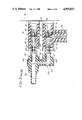
- FIG. 5 is a fragmentary side elevational view, partially in section, of an apparatus bushing, apparatus bushing extender, high voltage cable connected to a "T" shaped connector and an interconnecting link member constructed in accordance with the concepts of the invention just prior to assembly.
- FIG. 6 is the device of FIG. 5 fully assembled.
- FIG. 1 there is shown a fully screw-operated link member 200 according to the above-identified patent.
- Each assembly 230 has a bolt 254 positioned in a bore with a threaded end portion 258 and a head portion 256 containing a socket 268 which can accept a tool inserted through the open end of assembly 230.
- a shoulder 264 is engaged by leading surface of head portion 256 to pull link member 200 into place as threads 258 engage internally-threaded recess 296 of contact extender 290.
- FIGS. 2, 3 and 4 One approach to eliminating the potential problems of jamming or cross threading of the bolts 254 while employing the advantages of link member 200 is shown in FIGS. 2, 3 and 4 as more fully described in the above-identified application.
- a plug 215 with a cylindrical contact portion 218 is employed instead of the internally-threaded contact extenders 290.
- the externally threaded portion 216 serves to unite the parts in the same manner as the contact extenders 290.
- Link member 152' has in each of its legs 154 and 156 a socket 217 with one or more louvered rings 222 to make electrical contact between the walls of socket 217 and contact portion 218 of plug 215 as is illustrated in FIG. 3.
- FIG. 4 An alternative pin-and-socket arrangement is shown in FIG. 4 where plug 34 has a segmented bulbous end 40 for receipt within the smooth-walled sockets 212 of arms 154 and 156 of link member 152.
- FIG. 2 Assembly of the link member 152' to the bushing extender 26 and the "T" shaped connector 50 is shown in FIG. 2 and is accomplished by link operating system 134.
- a pushing arm 144 advances link 152' as operating handle 136 is rotated toward "T" shaped connector 50 about pivot pins 146 advancing the slot 140 along roller sleeve 130 mounted on pin 132 on member 120.
- the link 152' is separated by the opposite movememt of operating handle 136.
- the arms 154 and 156 are fully seated as are the various pin-and-socket combinations and the link 152' is firmly held in position.
- the operating handle 136 is moved to the fully horizontal position, the arms 154 and 156 are withdrawn and the pin-and-socket connections are broken and the link 152' can be fully removed.
- the link operating system 134 is large and bulky requiring not only the system 134 but also the bracket 72 and the members 120. It also requires a great deal of space and large open-front space so that the operating handle 136 can be rotated. It does offer a small reduction in the size of the link 152' since only one arm 158 is required. A single arm 158 with loadbreak facility is sufficient to test the high voltage cable and the bushing and there is no need for access to the second end of the link 152'.
- FIGS. 4, 5 and 6 a link 300 constructed in accordance with the concepts of the invention is shown.
- a high voltage cable is joined to a "T" shaped connector 50 by means of crimp connector 66 whose threaded aperture 68 receives the threaded end 36 of plug 215 which is further threaded into insulating bushing 302 fastened to apparatus wall 22 and received in arm 56 of "T" shaped connector 50.
- the contact portion 218 of plug 215 extends into the receptacle 304 of arm 54 of connector 50.
- Apparatus bushing 20 is fixed to apparatus wall 22 and receives apparatus bushing extender 26 which is fixed to it by the threaded portion 292 of contact extender 290. Internally threaded portion 296 of contact extender 290 extends into receptacle 308 of bushing extender 26.
- Link 300 is similar to link 152' of FIG. 3.
- a central body 152 of insulating elastomeric material 202 has molded to it at selected locations a layer of conductive elastomeric material 204.
- Extending from the opposite face of central body 152 are a pair of frusto-conically shaped legs 154' and 156.
- Leg 156 also contains a metallic tube 208 joined to the tube 206 by a buss bar 210 housed in central body portion 152.
- a pair of louvered contact rings 222 Placed in suitable recesses in the interior surface 217 of tube 208 are a pair of louvered contact rings 222 of the type fully disclosed in U.S. Pat. No. 4,186,985 issued Feb. 5, 1980, entitled Electrical Connector, by Frank M. Stepniak and Andrew A. Kominiak and assigned to the Assignee of the instant invention.
- contact portion 218 of plug 215 When leg 156 is fully seated in receptacle 304 in arm 54, contact portion 218 of plug 215 will be positioned in the end of tube 208 and within the contact rings 222 which will make electrical contact between contact portion 218 and tube 208 as is shown in FIG. 6.
- the bore through tube 206 is enlarged at its end, as at 306 for clearance and at 310 to provide a drive shoulder 264 engaged by the leading edge of head 256 of bolt 254 to pull leg 154' forward to seat in receptacle 308 of bushing extender 26 and at the same time leg 156 seats in receptacle 304 of arm 54, as shown in FIG. 6.
- An annular recess 312 behind the trailing surface of head 256 of bolt 254 receives an annular retaining ring 314 to effectively capture bolt 254 and limit its travel within the bore of tube 206.
- link 300 In applying the link 300, it is grasped by a hot stick (not shown) and positioned so that leg 154' enters receptacle 308 of bushing extender 26 and leg 156 enters receptacle 304 of arm 54 of connector 50 as is shown in FIG. 5.
- Link 300 may be pushed further to the right of FIG. 5 and the bolt 254 turned so as to enter the internally threaded portion 296 of contact extender 290.
- leg 154' is seated more tightly in receptacle 308 of extender 26
- leg 156 is seated more tightly in receptacle 304 of arm 54 and contact portion 218 of plug 215 enters more deeply into the end of tube 208 until all components are fully seated as shown in FIG. 6. Because bolt 254 is only advanced once leg 154' is seated, there is little chance of jamming or cross threading. Further, the pin- and-socket arrangement of contact portion 218 with rings 222 only engage as bolt 254 is tightened and do not affect bolt 254.
- bolt 254 is turned in the loosening direction until the trailing surface of head 256 engages retaining ring 314 after which the continued turning of bolt 254 exerts a positive force upon ring 314 causing separation of leg 154' from receptacle 308 and leg 156 from receptacle 304 and the separation of contact portion 218 from rings 222.
- the pin-and-socket arrangement of FIG. 4 could be used.
- the end of tube 208 could be left with a smooth interior surface 212 and the contact portion 218 of plug 215 could be replaced by a segmented bulbous end 40 of a plug 34.
- a ring (not shown) could be placed at the mouth of tube 208 to prevent unwanted withdrawl of plug 34. The operation of this embodiment would be the same as described above with respect to FIGS. 5 and 6.
Abstract
Description
Claims (9)
Priority Applications (7)
| Application Number | Priority Date | Filing Date | Title |
|---|---|---|---|
| US07/419,514 US4955823A (en) | 1989-10-10 | 1989-10-10 | 600-Amp hot stick-operable screw and pin-and-socket assembled connector system |
| CA002022949A CA2022949C (en) | 1989-10-10 | 1990-08-08 | 600-amp hot stick-operable screw and pin-and-socket assembled connector system |
| KR1019900014373A KR100222336B1 (en) | 1989-10-10 | 1990-09-12 | 600-amp hot stick-operable screw and pin-and- socket connector system |
| JP2246956A JP2506494B2 (en) | 1989-10-10 | 1990-09-17 | High voltage connector device |
| AU62671/90A AU617257B2 (en) | 1989-10-10 | 1990-09-19 | 600-amp hot stick-operable screw and pin-and-socket assembled connector system |
| EP90119039A EP0422503A1 (en) | 1989-10-10 | 1990-10-04 | A 600-amp hot stick-operable screw and pin-and-socket assembled connector system |
| DE199090119039T DE422503T1 (en) | 1989-10-10 | 1990-10-04 | OPERABLE WITH SHIFT ROD 600 AMP. CONNECTOR SYSTEM. |
Applications Claiming Priority (1)
| Application Number | Priority Date | Filing Date | Title |
|---|---|---|---|
| US07/419,514 US4955823A (en) | 1989-10-10 | 1989-10-10 | 600-Amp hot stick-operable screw and pin-and-socket assembled connector system |
Publications (1)
| Publication Number | Publication Date |
|---|---|
| US4955823A true US4955823A (en) | 1990-09-11 |
Family
ID=23662605
Family Applications (1)
| Application Number | Title | Priority Date | Filing Date |
|---|---|---|---|
| US07/419,514 Expired - Lifetime US4955823A (en) | 1989-10-10 | 1989-10-10 | 600-Amp hot stick-operable screw and pin-and-socket assembled connector system |
Country Status (7)
| Country | Link |
|---|---|
| US (1) | US4955823A (en) |
| EP (1) | EP0422503A1 (en) |
| JP (1) | JP2506494B2 (en) |
| KR (1) | KR100222336B1 (en) |
| AU (1) | AU617257B2 (en) |
| CA (1) | CA2022949C (en) |
| DE (1) | DE422503T1 (en) |
Cited By (48)
| Publication number | Priority date | Publication date | Assignee | Title |
|---|---|---|---|---|
| US5092798A (en) * | 1991-04-30 | 1992-03-03 | Cooper Power Systems, Inc. | Electrical bushing |
| US5215475A (en) * | 1992-07-02 | 1993-06-01 | Amerace Corporation | Devices for use with high voltage system components for the safe expulsion of conductive moisture within such components |
| US5221220A (en) * | 1992-04-09 | 1993-06-22 | Cooper Power Systems, Inc. | Standoff bushing assembly |
| US6042407A (en) * | 1998-04-23 | 2000-03-28 | Hubbell Incorporated | Safe-operating load reducing tap plug and method using the same |
| US6364216B1 (en) * | 2001-02-20 | 2002-04-02 | G&W Electric Co. | Universal power connector for joining flexible cables to rigid devices in any of many configurations |
| US6520795B1 (en) | 2001-08-02 | 2003-02-18 | Hubbell Incorporated | Load reducing electrical device |
| US20050136733A1 (en) * | 2003-12-22 | 2005-06-23 | Gorrell Brian E. | Remote high voltage splitter block |
| US20060150779A1 (en) * | 2005-01-13 | 2006-07-13 | Rider Jack H | Line work tool and method thereof |
| US20060160413A1 (en) * | 2005-01-19 | 2006-07-20 | Ekstrom Industries, Inc. | Terminal block jumper |
| WO2007019459A1 (en) | 2005-08-08 | 2007-02-15 | Cooper Technologies Company | Apparatus, system and methods for deadfront visible loadbreak |
| US20070278187A1 (en) * | 2006-05-31 | 2007-12-06 | Thomas & Betts International, Inc. | Visible open indicator |
| US20070278188A1 (en) * | 2006-05-31 | 2007-12-06 | Thomas & Betts International, Inc. | Connector system for an insulated switch with provision for grounding and visible break |
| US20080026636A1 (en) * | 2006-07-27 | 2008-01-31 | Jackson Denton L | Adjustable feed through bushing base |
| US20080142344A1 (en) * | 2006-12-18 | 2008-06-19 | Caterpillar Inc. | Electrical shorting system |
| US7494355B2 (en) | 2007-02-20 | 2009-02-24 | Cooper Technologies Company | Thermoplastic interface and shield assembly for separable insulated connector system |
| US20090061680A1 (en) * | 2006-07-27 | 2009-03-05 | Jackson Iii Denton L | Adjustable feed through bushing base with lifting means |
| US20090141412A1 (en) * | 2006-12-18 | 2009-06-04 | Caterpillar Inc. | Electrical interface system |
| US7568927B2 (en) | 2007-04-23 | 2009-08-04 | Cooper Technologies Company | Separable insulated connector system |
| US7572133B2 (en) | 2005-11-14 | 2009-08-11 | Cooper Technologies Company | Separable loadbreak connector and system |
| US7578682B1 (en) | 2008-02-25 | 2009-08-25 | Cooper Technologies Company | Dual interface separable insulated connector with overmolded faraday cage |
| US7632120B2 (en) | 2005-07-29 | 2009-12-15 | Cooper Technologies Company | Separable loadbreak connector and system with shock absorbent fault closure stop |
| US7633741B2 (en) | 2007-04-23 | 2009-12-15 | Cooper Technologies Company | Switchgear bus support system and method |
| US7661979B2 (en) | 2007-06-01 | 2010-02-16 | Cooper Technologies Company | Jacket sleeve with grippable tabs for a cable connector |
| US7666012B2 (en) | 2007-03-20 | 2010-02-23 | Cooper Technologies Company | Separable loadbreak connector for making or breaking an energized connection in a power distribution network |
| US7670162B2 (en) | 2008-02-25 | 2010-03-02 | Cooper Technologies Company | Separable connector with interface undercut |
| US7695291B2 (en) | 2007-10-31 | 2010-04-13 | Cooper Technologies Company | Fully insulated fuse test and ground device |
| US20100200379A1 (en) * | 2007-09-07 | 2010-08-12 | Frederik Paul Schoten | Quickly exchangeable switching device in fixed type medium voltage switchgear system |
| US7811113B2 (en) | 2008-03-12 | 2010-10-12 | Cooper Technologies Company | Electrical connector with fault closure lockout |
| US7854620B2 (en) | 2007-02-20 | 2010-12-21 | Cooper Technologies Company | Shield housing for a separable connector |
| US7878849B2 (en) | 2008-04-11 | 2011-02-01 | Cooper Technologies Company | Extender for a separable insulated connector |
| US7905735B2 (en) | 2008-02-25 | 2011-03-15 | Cooper Technologies Company | Push-then-pull operation of a separable connector system |
| US7950939B2 (en) | 2007-02-22 | 2011-05-31 | Cooper Technologies Company | Medium voltage separable insulated energized break connector |
| US7950940B2 (en) | 2008-02-25 | 2011-05-31 | Cooper Technologies Company | Separable connector with reduced surface contact |
| US7958631B2 (en) | 2008-04-11 | 2011-06-14 | Cooper Technologies Company | Method of using an extender for a separable insulated connector |
| US7963782B2 (en) | 2008-02-25 | 2011-06-21 | Cooper Technologies Company | Separable connector system with a position indicator |
| US20110189887A1 (en) * | 2010-02-03 | 2011-08-04 | Thomas & Betts International, Inc. | Visible open for switchgear assembly |
| US8056226B2 (en) | 2008-02-25 | 2011-11-15 | Cooper Technologies Company | Method of manufacturing a dual interface separable insulated connector with overmolded faraday cage |
| US8109776B2 (en) | 2008-02-27 | 2012-02-07 | Cooper Technologies Company | Two-material separable insulated connector |
| US20120202392A1 (en) * | 2011-02-04 | 2012-08-09 | Thomas & Betts International, Inc. | Triple cam-operated link |
| US8388381B2 (en) | 2010-07-21 | 2013-03-05 | Thomas & Betts International, Inc. | Visible open for switchgear assembly |
| US20150288093A1 (en) * | 2014-04-07 | 2015-10-08 | S&C Electric Company | Replaceable bushing for electrical equipment |
| US20150295372A1 (en) * | 2014-04-10 | 2015-10-15 | S&C Electric Company | Adjustable bus bar for power distribution equipment |
| US20150318635A1 (en) * | 2013-01-14 | 2015-11-05 | Tyco Electronics Raychem Gmbh | Detachable Cable Joint With Three Sockets |
| US20160141801A1 (en) * | 2014-11-17 | 2016-05-19 | Thomas & Betts International, Llc | Grounding link for electrical connector mechanism |
| US9948049B2 (en) * | 2016-04-13 | 2018-04-17 | Paccar Inc | Starter post relocation assembly |
| US20180316124A1 (en) * | 2017-04-27 | 2018-11-01 | Shad Patrick Fleming | Insulated External Parking Bushing |
| US11024985B2 (en) * | 2017-04-27 | 2021-06-01 | Shad Patrick Fleming | Insulated external parking bushing |
| US11424577B2 (en) * | 2018-11-07 | 2022-08-23 | Harting Electric Stiftung & Co. Kg | High-current electrical connector and electrical connector system |
Families Citing this family (9)
| Publication number | Priority date | Publication date | Assignee | Title |
|---|---|---|---|---|
| KR100341113B1 (en) * | 1999-12-30 | 2002-06-20 | 권문구 | Low smoke and flame resistant composition |
| KR100401927B1 (en) * | 2000-10-17 | 2003-10-11 | 김명대 | Strut for supporting communication fiber optic cable |
| KR100394547B1 (en) * | 2000-12-19 | 2003-08-14 | 동일고무벨트주식회사 | The method of improving properties of epdm rubber |
| KR100882048B1 (en) * | 2007-01-12 | 2009-02-09 | 엘에스전선 주식회사 | Connector with high current capability |
| US9325104B2 (en) | 2013-05-24 | 2016-04-26 | Thomas & Betts International, Inc. | Gelatinous dielectric material for high voltage connector |
| US9437374B2 (en) | 2013-05-24 | 2016-09-06 | Thomas & Betts International Llc | Automated grounding device with visual indication |
| US9443681B2 (en) | 2013-07-29 | 2016-09-13 | Thomas & Betts International Llc | Flexible dielectric material for high voltage switch |
| US9520007B2 (en) | 2014-05-05 | 2016-12-13 | James C. Stippich | Remotely operable lockout system |
| JP6850420B2 (en) * | 2016-12-02 | 2021-03-31 | 日立金属株式会社 | Insulated electric wires and cables using non-halogen flame-retardant resin composition |
Citations (6)
| Publication number | Priority date | Publication date | Assignee | Title |
|---|---|---|---|---|
| GB1444767A (en) * | 1972-10-02 | 1976-08-04 | Itt | Electrical connector |
| US4202591A (en) * | 1978-10-10 | 1980-05-13 | Amerace Corporation | Apparatus for the remote grounding, connection and disconnection of high voltage electrical circuits |
| US4354721A (en) * | 1980-12-31 | 1982-10-19 | Amerace Corporation | Attachment arrangement for high voltage electrical connector |
| US4758175A (en) * | 1986-09-26 | 1988-07-19 | Biw Cable Systems, Inc. | Aircraft ground power cable |
| US4799895A (en) * | 1987-06-22 | 1989-01-24 | Amerace Corporation | 600-Amp hot stick operable screw-assembled connector system |
| US4891016A (en) * | 1989-03-29 | 1990-01-02 | Amerace Corporation | 600-Amp hot stick-operable pin-and-socket assembled connector system |
Family Cites Families (1)
| Publication number | Priority date | Publication date | Assignee | Title |
|---|---|---|---|---|
| US3519977A (en) * | 1968-01-11 | 1970-07-07 | Whitaker Cable Corp | High amperage quick disconnect electric coupling structure |
-
1989
- 1989-10-10 US US07/419,514 patent/US4955823A/en not_active Expired - Lifetime
-
1990
- 1990-08-08 CA CA002022949A patent/CA2022949C/en not_active Expired - Lifetime
- 1990-09-12 KR KR1019900014373A patent/KR100222336B1/en not_active IP Right Cessation
- 1990-09-17 JP JP2246956A patent/JP2506494B2/en not_active Expired - Fee Related
- 1990-09-19 AU AU62671/90A patent/AU617257B2/en not_active Ceased
- 1990-10-04 DE DE199090119039T patent/DE422503T1/en active Pending
- 1990-10-04 EP EP90119039A patent/EP0422503A1/en not_active Withdrawn
Patent Citations (6)
| Publication number | Priority date | Publication date | Assignee | Title |
|---|---|---|---|---|
| GB1444767A (en) * | 1972-10-02 | 1976-08-04 | Itt | Electrical connector |
| US4202591A (en) * | 1978-10-10 | 1980-05-13 | Amerace Corporation | Apparatus for the remote grounding, connection and disconnection of high voltage electrical circuits |
| US4354721A (en) * | 1980-12-31 | 1982-10-19 | Amerace Corporation | Attachment arrangement for high voltage electrical connector |
| US4758175A (en) * | 1986-09-26 | 1988-07-19 | Biw Cable Systems, Inc. | Aircraft ground power cable |
| US4799895A (en) * | 1987-06-22 | 1989-01-24 | Amerace Corporation | 600-Amp hot stick operable screw-assembled connector system |
| US4891016A (en) * | 1989-03-29 | 1990-01-02 | Amerace Corporation | 600-Amp hot stick-operable pin-and-socket assembled connector system |
Cited By (78)
| Publication number | Priority date | Publication date | Assignee | Title |
|---|---|---|---|---|
| US5092798A (en) * | 1991-04-30 | 1992-03-03 | Cooper Power Systems, Inc. | Electrical bushing |
| US5221220A (en) * | 1992-04-09 | 1993-06-22 | Cooper Power Systems, Inc. | Standoff bushing assembly |
| US5215475A (en) * | 1992-07-02 | 1993-06-01 | Amerace Corporation | Devices for use with high voltage system components for the safe expulsion of conductive moisture within such components |
| US6042407A (en) * | 1998-04-23 | 2000-03-28 | Hubbell Incorporated | Safe-operating load reducing tap plug and method using the same |
| EP1362392A4 (en) * | 2001-02-20 | 2007-11-14 | G & W Electric | Universal power connector for joining flexible cable to rigid devices in any of many configurations |
| WO2002067385A1 (en) * | 2001-02-20 | 2002-08-29 | G & W Electric Company | Universal power connector for joining flexible cable to rigid devices in any of many configurations |
| EP1362392A1 (en) * | 2001-02-20 | 2003-11-19 | G & W ELECTRIC COMPANY | Universal power connector for joining flexible cable to rigid devices in any of many configurations |
| US6364216B1 (en) * | 2001-02-20 | 2002-04-02 | G&W Electric Co. | Universal power connector for joining flexible cables to rigid devices in any of many configurations |
| CN1307751C (en) * | 2001-02-20 | 2007-03-28 | G及W电气公司 | Universal power connector for joining flexible cable to rigid devices in any of many configurations |
| US6520795B1 (en) | 2001-08-02 | 2003-02-18 | Hubbell Incorporated | Load reducing electrical device |
| US20050136733A1 (en) * | 2003-12-22 | 2005-06-23 | Gorrell Brian E. | Remote high voltage splitter block |
| US7181995B2 (en) | 2005-01-13 | 2007-02-27 | Rider Jack H | Line work tool and method thereof |
| US20060150779A1 (en) * | 2005-01-13 | 2006-07-13 | Rider Jack H | Line work tool and method thereof |
| US7153157B2 (en) * | 2005-01-19 | 2006-12-26 | Ekstrom Industries, Inc. | Terminal block jumper |
| US20060160413A1 (en) * | 2005-01-19 | 2006-07-20 | Ekstrom Industries, Inc. | Terminal block jumper |
| US7632120B2 (en) | 2005-07-29 | 2009-12-15 | Cooper Technologies Company | Separable loadbreak connector and system with shock absorbent fault closure stop |
| WO2007019459A1 (en) | 2005-08-08 | 2007-02-15 | Cooper Technologies Company | Apparatus, system and methods for deadfront visible loadbreak |
| EP2267848A3 (en) * | 2005-08-08 | 2011-03-02 | Cooper Technologies Company | Apparatus, system and methods for deadfront visible loadbreak |
| US7384287B2 (en) | 2005-08-08 | 2008-06-10 | Cooper Technologies Company | Apparatus, system and methods for deadfront visible loadbreak |
| US8038457B2 (en) | 2005-11-14 | 2011-10-18 | Cooper Technologies Company | Separable electrical connector with reduced risk of flashover |
| US7572133B2 (en) | 2005-11-14 | 2009-08-11 | Cooper Technologies Company | Separable loadbreak connector and system |
| US7901227B2 (en) | 2005-11-14 | 2011-03-08 | Cooper Technologies Company | Separable electrical connector with reduced risk of flashover |
| US20070278187A1 (en) * | 2006-05-31 | 2007-12-06 | Thomas & Betts International, Inc. | Visible open indicator |
| US7501598B2 (en) | 2006-05-31 | 2009-03-10 | Thomas & Betts International, Inc. | Connector system for an insulated switch with provision for grounding and visible break |
| US7579571B2 (en) | 2006-05-31 | 2009-08-25 | Thomas & Betts International, Inc. | Visible open indicator |
| US20070278188A1 (en) * | 2006-05-31 | 2007-12-06 | Thomas & Betts International, Inc. | Connector system for an insulated switch with provision for grounding and visible break |
| US20090061680A1 (en) * | 2006-07-27 | 2009-03-05 | Jackson Iii Denton L | Adjustable feed through bushing base with lifting means |
| US7427207B2 (en) * | 2006-07-27 | 2008-09-23 | Jackson Iii Denton L | Adjustable feed through bushing base |
| US20080026636A1 (en) * | 2006-07-27 | 2008-01-31 | Jackson Denton L | Adjustable feed through bushing base |
| US7674122B2 (en) * | 2006-07-27 | 2010-03-09 | Jackson Iii Denton L | Adjustable feed through bushing base with lifting means |
| US20090141412A1 (en) * | 2006-12-18 | 2009-06-04 | Caterpillar Inc. | Electrical interface system |
| US20080142344A1 (en) * | 2006-12-18 | 2008-06-19 | Caterpillar Inc. | Electrical shorting system |
| US7616421B2 (en) | 2006-12-18 | 2009-11-10 | Caterpillar Inc. | Electrical interface system |
| US7789685B2 (en) | 2006-12-18 | 2010-09-07 | Caterpillar Inc | Electrical shorting system |
| US7494355B2 (en) | 2007-02-20 | 2009-02-24 | Cooper Technologies Company | Thermoplastic interface and shield assembly for separable insulated connector system |
| US7854620B2 (en) | 2007-02-20 | 2010-12-21 | Cooper Technologies Company | Shield housing for a separable connector |
| US7950939B2 (en) | 2007-02-22 | 2011-05-31 | Cooper Technologies Company | Medium voltage separable insulated energized break connector |
| US7666012B2 (en) | 2007-03-20 | 2010-02-23 | Cooper Technologies Company | Separable loadbreak connector for making or breaking an energized connection in a power distribution network |
| US7862354B2 (en) | 2007-03-20 | 2011-01-04 | Cooper Technologies Company | Separable loadbreak connector and system for reducing damage due to fault closure |
| US7633741B2 (en) | 2007-04-23 | 2009-12-15 | Cooper Technologies Company | Switchgear bus support system and method |
| US7568927B2 (en) | 2007-04-23 | 2009-08-04 | Cooper Technologies Company | Separable insulated connector system |
| US7909635B2 (en) | 2007-06-01 | 2011-03-22 | Cooper Technologies Company | Jacket sleeve with grippable tabs for a cable connector |
| US7661979B2 (en) | 2007-06-01 | 2010-02-16 | Cooper Technologies Company | Jacket sleeve with grippable tabs for a cable connector |
| US7883356B2 (en) | 2007-06-01 | 2011-02-08 | Cooper Technologies Company | Jacket sleeve with grippable tabs for a cable connector |
| US20100200379A1 (en) * | 2007-09-07 | 2010-08-12 | Frederik Paul Schoten | Quickly exchangeable switching device in fixed type medium voltage switchgear system |
| US8043129B2 (en) * | 2007-09-07 | 2011-10-25 | Eaton Electric B.V. | Quickly exchangeable switching device in fixed type medium voltage switchgear system |
| US7695291B2 (en) | 2007-10-31 | 2010-04-13 | Cooper Technologies Company | Fully insulated fuse test and ground device |
| US7578682B1 (en) | 2008-02-25 | 2009-08-25 | Cooper Technologies Company | Dual interface separable insulated connector with overmolded faraday cage |
| US7905735B2 (en) | 2008-02-25 | 2011-03-15 | Cooper Technologies Company | Push-then-pull operation of a separable connector system |
| US7670162B2 (en) | 2008-02-25 | 2010-03-02 | Cooper Technologies Company | Separable connector with interface undercut |
| US7950940B2 (en) | 2008-02-25 | 2011-05-31 | Cooper Technologies Company | Separable connector with reduced surface contact |
| US7963782B2 (en) | 2008-02-25 | 2011-06-21 | Cooper Technologies Company | Separable connector system with a position indicator |
| US8056226B2 (en) | 2008-02-25 | 2011-11-15 | Cooper Technologies Company | Method of manufacturing a dual interface separable insulated connector with overmolded faraday cage |
| US8152547B2 (en) | 2008-02-27 | 2012-04-10 | Cooper Technologies Company | Two-material separable insulated connector band |
| US8109776B2 (en) | 2008-02-27 | 2012-02-07 | Cooper Technologies Company | Two-material separable insulated connector |
| US7811113B2 (en) | 2008-03-12 | 2010-10-12 | Cooper Technologies Company | Electrical connector with fault closure lockout |
| US7958631B2 (en) | 2008-04-11 | 2011-06-14 | Cooper Technologies Company | Method of using an extender for a separable insulated connector |
| US7878849B2 (en) | 2008-04-11 | 2011-02-01 | Cooper Technologies Company | Extender for a separable insulated connector |
| US8408925B2 (en) | 2010-02-03 | 2013-04-02 | Thomas & Betts International, Inc. | Visible open for switchgear assembly |
| US20110189887A1 (en) * | 2010-02-03 | 2011-08-04 | Thomas & Betts International, Inc. | Visible open for switchgear assembly |
| US8388381B2 (en) | 2010-07-21 | 2013-03-05 | Thomas & Betts International, Inc. | Visible open for switchgear assembly |
| US8449310B2 (en) * | 2011-02-04 | 2013-05-28 | Thomas & Betts International, Inc. | Triple cam-operated link |
| US20120202392A1 (en) * | 2011-02-04 | 2012-08-09 | Thomas & Betts International, Inc. | Triple cam-operated link |
| US20150318635A1 (en) * | 2013-01-14 | 2015-11-05 | Tyco Electronics Raychem Gmbh | Detachable Cable Joint With Three Sockets |
| US9537247B2 (en) * | 2013-01-14 | 2017-01-03 | Tyco Electronics Raychem Gmbh | Detachable cable joint with three sockets |
| US9362663B2 (en) * | 2014-04-07 | 2016-06-07 | S&C Electric Company | Replaceable bushing for electrical equipment |
| US20150288093A1 (en) * | 2014-04-07 | 2015-10-08 | S&C Electric Company | Replaceable bushing for electrical equipment |
| CN106463881A (en) * | 2014-04-07 | 2017-02-22 | 施恩禧电气公司 | Replaceable bushing for electrical equipment |
| CN106463881B (en) * | 2014-04-07 | 2019-11-08 | 施恩禧电气公司 | Interchangeable casing for electrical equipment |
| US20150295372A1 (en) * | 2014-04-10 | 2015-10-15 | S&C Electric Company | Adjustable bus bar for power distribution equipment |
| US9385493B2 (en) * | 2014-04-10 | 2016-07-05 | S&C Electric Company | Adjustable bus bar for power distribution equipment |
| US9660402B2 (en) * | 2014-04-10 | 2017-05-23 | S&C Electric Company | Conductor assembly for power distribution equipment |
| US20160141801A1 (en) * | 2014-11-17 | 2016-05-19 | Thomas & Betts International, Llc | Grounding link for electrical connector mechanism |
| US9954315B2 (en) * | 2014-11-17 | 2018-04-24 | Thomas & Betts International Llc | Grounding link for electrical connector mechanism |
| US9948049B2 (en) * | 2016-04-13 | 2018-04-17 | Paccar Inc | Starter post relocation assembly |
| US20180316124A1 (en) * | 2017-04-27 | 2018-11-01 | Shad Patrick Fleming | Insulated External Parking Bushing |
| US11024985B2 (en) * | 2017-04-27 | 2021-06-01 | Shad Patrick Fleming | Insulated external parking bushing |
| US11424577B2 (en) * | 2018-11-07 | 2022-08-23 | Harting Electric Stiftung & Co. Kg | High-current electrical connector and electrical connector system |
Also Published As
| Publication number | Publication date |
|---|---|
| JP2506494B2 (en) | 1996-06-12 |
| KR910008888A (en) | 1991-05-31 |
| AU617257B2 (en) | 1991-11-21 |
| DE422503T1 (en) | 1991-11-28 |
| JPH03145077A (en) | 1991-06-20 |
| KR100222336B1 (en) | 1999-10-01 |
| CA2022949C (en) | 1993-10-26 |
| CA2022949A1 (en) | 1991-04-11 |
| AU6267190A (en) | 1991-04-18 |
| EP0422503A1 (en) | 1991-04-17 |
Similar Documents
| Publication | Publication Date | Title |
|---|---|---|
| US4955823A (en) | 600-Amp hot stick-operable screw and pin-and-socket assembled connector system | |
| US4891016A (en) | 600-Amp hot stick-operable pin-and-socket assembled connector system | |
| CA2056226C (en) | Improved high voltage elbow | |
| US4799895A (en) | 600-Amp hot stick operable screw-assembled connector system | |
| EP0649189B1 (en) | Electrical connector assembly and method for connecting the same | |
| TWI433419B (en) | Apparatus, system and methods for deadfront visible loadbreak | |
| US7021964B1 (en) | RJ “F”, modular connector for coaxial cables | |
| EP0147979B1 (en) | High voltage connector | |
| US3671922A (en) | Push-on connector | |
| US6520795B1 (en) | Load reducing electrical device | |
| JPS63500552A (en) | drawer connector | |
| CA2330097A1 (en) | Safe-operating load reducing tap plug and method for using the same | |
| JPS6350820B2 (en) | ||
| EP0105810A3 (en) | An electrical connector having an anti-decoupling device | |
| CN109713517B (en) | Electric connector with plug and socket not needing repeated connection and separation | |
| KR20010043279A (en) | Safety interlock device | |
| CA2056928A1 (en) | Test connector | |
| US4776089A (en) | Method of assembling tap plug to cable connector | |
| US5381308A (en) | Electrical component arranged for locking and electrically conecting in an opening of a panel fromexternally of the panel | |
| EP0535210B1 (en) | Electrical power connector | |
| DE2415486A1 (en) | ELECTRIC CONNECTOR | |
| US3644871A (en) | Electric connector | |
| GB2223134A (en) | Electrical plug and socket connector | |
| EP0465525A1 (en) | Electrical connector |
Legal Events
| Date | Code | Title | Description |
|---|---|---|---|
| AS | Assignment |
Owner name: AMERACE CORPORATION, NEW JERSEY Free format text: ASSIGNMENT OF ASSIGNORS INTEREST.;ASSIGNOR:LUZZI, GLENN J.;REEL/FRAME:005155/0560 Effective date: 19890928 |
|
| STCF | Information on status: patent grant |
Free format text: PATENTED CASE |
|
| AS | Assignment |
Owner name: MANUFACTURERS HANOVER TRUST COMPANY, NEW YORK Free format text: SECURITY INTEREST;ASSIGNOR:AMERACE CORPORATION;REEL/FRAME:005465/0013 Effective date: 19900731 |
|
| FEPP | Fee payment procedure |
Free format text: PAYOR NUMBER ASSIGNED (ORIGINAL EVENT CODE: ASPN); ENTITY STATUS OF PATENT OWNER: LARGE ENTITY |
|
| FPAY | Fee payment |
Year of fee payment: 4 |
|
| FPAY | Fee payment |
Year of fee payment: 8 |
|
| AS | Assignment |
Owner name: THOMAS & BETTS INTERNATIONAL, INC., A CORP. OF DEL Free format text: ASSIGNMENT OF ASSIGNORS INTEREST;ASSIGNOR:AMERACE CORPORATION, A CORP OF DELAWARE;REEL/FRAME:009027/0401 Effective date: 19980309 |
|
| FEPP | Fee payment procedure |
Free format text: PAYOR NUMBER ASSIGNED (ORIGINAL EVENT CODE: ASPN); ENTITY STATUS OF PATENT OWNER: LARGE ENTITY Free format text: PAYER NUMBER DE-ASSIGNED (ORIGINAL EVENT CODE: RMPN); ENTITY STATUS OF PATENT OWNER: LARGE ENTITY |
|
| FPAY | Fee payment |
Year of fee payment: 12 |