US4959697A - Short channel junction field effect transistor - Google Patents
Short channel junction field effect transistor Download PDFInfo
- Publication number
- US4959697A US4959697A US07/481,803 US48180390A US4959697A US 4959697 A US4959697 A US 4959697A US 48180390 A US48180390 A US 48180390A US 4959697 A US4959697 A US 4959697A
- Authority
- US
- United States
- Prior art keywords
- gate
- conductivity type
- regions
- region
- subsurface
- Prior art date
- Legal status (The legal status is an assumption and is not a legal conclusion. Google has not performed a legal analysis and makes no representation as to the accuracy of the status listed.)
- Expired - Lifetime
Links
- 230000005669 field effect Effects 0.000 title claims abstract description 11
- 238000000034 method Methods 0.000 abstract description 6
- 230000008569 process Effects 0.000 abstract description 6
- 239000002019 doping agent Substances 0.000 abstract description 5
- 238000004519 manufacturing process Methods 0.000 abstract description 5
- 230000004044 response Effects 0.000 abstract description 4
- 238000010348 incorporation Methods 0.000 abstract description 2
- 108091006146 Channels Proteins 0.000 description 46
- 238000009792 diffusion process Methods 0.000 description 10
- 238000002513 implantation Methods 0.000 description 9
- 239000004065 semiconductor Substances 0.000 description 8
- 230000015572 biosynthetic process Effects 0.000 description 6
- 239000000758 substrate Substances 0.000 description 5
- ZOXJGFHDIHLPTG-UHFFFAOYSA-N Boron Chemical compound [B] ZOXJGFHDIHLPTG-UHFFFAOYSA-N 0.000 description 4
- 229910052796 boron Inorganic materials 0.000 description 4
- 238000005468 ion implantation Methods 0.000 description 4
- 229920002120 photoresistant polymer Polymers 0.000 description 4
- OAICVXFJPJFONN-UHFFFAOYSA-N Phosphorus Chemical compound [P] OAICVXFJPJFONN-UHFFFAOYSA-N 0.000 description 3
- 229910052698 phosphorus Inorganic materials 0.000 description 3
- 239000011574 phosphorus Substances 0.000 description 3
- 230000009467 reduction Effects 0.000 description 3
- 230000015556 catabolic process Effects 0.000 description 2
- 230000008030 elimination Effects 0.000 description 2
- 238000003379 elimination reaction Methods 0.000 description 2
- 230000000873 masking effect Effects 0.000 description 2
- 108010075750 P-Type Calcium Channels Proteins 0.000 description 1
- 230000005540 biological transmission Effects 0.000 description 1
- 238000005520 cutting process Methods 0.000 description 1
- 230000001934 delay Effects 0.000 description 1
- 230000000694 effects Effects 0.000 description 1
- 239000007943 implant Substances 0.000 description 1
- 230000010354 integration Effects 0.000 description 1
- 239000000463 material Substances 0.000 description 1
- 230000005855 radiation Effects 0.000 description 1
- 229910052710 silicon Inorganic materials 0.000 description 1
- 239000010703 silicon Substances 0.000 description 1
- 238000005549 size reduction Methods 0.000 description 1
Images


Classifications
-
- H—ELECTRICITY
- H01—ELECTRIC ELEMENTS
- H01L—SEMICONDUCTOR DEVICES NOT COVERED BY CLASS H10
- H01L29/00—Semiconductor devices adapted for rectifying, amplifying, oscillating or switching, or capacitors or resistors with at least one potential-jump barrier or surface barrier, e.g. PN junction depletion layer or carrier concentration layer; Details of semiconductor bodies or of electrodes thereof ; Multistep manufacturing processes therefor
- H01L29/66—Types of semiconductor device ; Multistep manufacturing processes therefor
- H01L29/66007—Multistep manufacturing processes
- H01L29/66075—Multistep manufacturing processes of devices having semiconductor bodies comprising group 14 or group 13/15 materials
- H01L29/66227—Multistep manufacturing processes of devices having semiconductor bodies comprising group 14 or group 13/15 materials the devices being controllable only by the electric current supplied or the electric potential applied, to an electrode which does not carry the current to be rectified, amplified or switched, e.g. three-terminal devices
- H01L29/66409—Unipolar field-effect transistors
- H01L29/66893—Unipolar field-effect transistors with a PN junction gate, i.e. JFET
- H01L29/66901—Unipolar field-effect transistors with a PN junction gate, i.e. JFET with a PN homojunction gate
-
- H—ELECTRICITY
- H01—ELECTRIC ELEMENTS
- H01L—SEMICONDUCTOR DEVICES NOT COVERED BY CLASS H10
- H01L29/00—Semiconductor devices adapted for rectifying, amplifying, oscillating or switching, or capacitors or resistors with at least one potential-jump barrier or surface barrier, e.g. PN junction depletion layer or carrier concentration layer; Details of semiconductor bodies or of electrodes thereof ; Multistep manufacturing processes therefor
- H01L29/02—Semiconductor bodies ; Multistep manufacturing processes therefor
- H01L29/06—Semiconductor bodies ; Multistep manufacturing processes therefor characterised by their shape; characterised by the shapes, relative sizes, or dispositions of the semiconductor regions ; characterised by the concentration or distribution of impurities within semiconductor regions
- H01L29/10—Semiconductor bodies ; Multistep manufacturing processes therefor characterised by their shape; characterised by the shapes, relative sizes, or dispositions of the semiconductor regions ; characterised by the concentration or distribution of impurities within semiconductor regions with semiconductor regions connected to an electrode not carrying current to be rectified, amplified or switched and such electrode being part of a semiconductor device which comprises three or more electrodes
- H01L29/1025—Channel region of field-effect devices
- H01L29/1029—Channel region of field-effect devices of field-effect transistors
- H01L29/1058—Channel region of field-effect devices of field-effect transistors with PN junction gate
Definitions
- the invention relates to junction field effect transistors and more particularly junction field effect transistors suitable for integration with bipolar transistors into integrated circuits.
- JFET Junction field effect transistor
- a bipolar junction transistor has base, emitter and collector regions.
- a JFET has gate, channel, source and drain regions. Frequently, a JFET is a symmetric device and the drain and source regions are indistinguishable until connected into a circuit. Where the base region of the bipolar device is of a like conductivity type with the source/drain regions of the JFET, all three regions can be produced in a single diffusion or implantation step.
- Location of various diffused or implanted regions in an integrated circuit is controlled by exposing only selected portions of the surface of the semiconductor material to diffusion or ion implantation by well known processes. Masks are used to control exposure of photoresist layers laid over the surface of the semiconductor to actinic radiation. After development of the photoresist layer exposes the desired portions of the semiconductor surface, the appropriate diffusion or implantation step is taken. Each implantation step involves a number of substeps.
- a JFET gate region comprises a portion of a lightly doped n conductivity type epitaxial layer isolated within a p type region over a substrate.
- the gate region also includes a highly conductive buried layer underlying active regions of the device to enhance gate conductivity.
- Two symmetric, diffused moderately doped p type regions are provided at spaced apart intervals over the buried layer within the gate region to provide a source and a drain. The source/drain diffusion is compatible with formation of base regions for npn bipolar transistors elsewhere on the device surface.
- Compton provides a single lightly doped p type subsurface channel for connecting the diffused source and drain regions.
- the transconductance requirements of the JFET are met by varying the width of the channel.
- Between the subsurface channel and the surface of the semiconductor device are implanted subregions of the gate region including a moderately doped n type cap and a heavily doped n type top gate.
- the top gate overlaps the lateral bounds of the channel to provide a low resistance electrical path from the pn junction between the top gate and the channel to the buried layer.
- the moderately doped caps space the top gate from the source and drain regions to avoid creation of a pn junction between these relatively heavily doped regions which would be characterized by a low reverse breakdown voltage.
- a gate electrode in Compton's device is attached to a heavily doped n type diffusion region, which provides a low resistance connection between an electrode and the gate region.
- Operation of the JFET is conventional, a voltage is applied to the gate region by the gate electrode to reverse bias the pn junctions between the gate region and the source, drain and particularly the channel regions. As the reverse bias voltage is increased, depletion regions adjacent the pn junctions expand, eventually cutting off the channel region beneath the top gate. Doping of the top gate is selected so that a space charge region develops under reverse bias voltage into the channel primarily from its junction with the top gate. To provide a reasonably high speed device, the current path through the top gate to the gate electrode must be highly conductive.
- frequency response of the Compton device in A.C. operation is affected by the distance the gate current must travel.
- Charge taken from or transmitted to the space charge region adjacent the top gate passes laterally across the width of the top gate.
- the charge travels between the highly conductive buried layer and the top gate around the lateral bounds of the channel.
- the heavily doped region adjacent the gate electrode provides a low resistance path for the gate charge.
- a space charge region also develops under reverse bias adjacent the deeper junction between the gate and the channel. Charge moves directly between this junction and the buried layer under reverse biasing.
- the lower space charge region which develops provides a relatively small part of the total pinch-off effect.
- top gate must be made highly conductive to compensate for delays introduced because of its width.
- Fabrication of a bounded top gate is also a complicated process requiring three separate maskings of the device to produce the channel, the cap and the top gate.
- the present invention provides an integrable JFET with an upper gate which is simpler to fabricate than devices taught by the prior art.
- the disclosed junction field effect transistor is formed in an n conductivity type gate region formed within a p type well.
- a heavily doped n type buried layer is disposed beneath the surface of the isolated gate region to enhance conductivity of the gate region.
- a pair of spaced-apart p type regions extend partway into the gate region from the surface thereof. The spaced-apart regions are connected by a plurality of subsurface p type channels.
- the dopant concentration of the upper gate region can be reduced.
- the upper gate regions accordingly need not be insulated from the heavily doped p type source and drain regions. Additionally, the upper gates are formed through the same mask as the subsurface channels insuring optimal alignment of the gates with the channels and allowing elimination of two maskings of the device during manufacture.
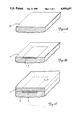
- FIGS. 1A through 1H depict formation of the various conductivity regions of the inventive junction field effect transistor
- FIG. 2 is a combined cross section and surface elevational view of the JFET of the invention along section 2--2 of FIG. 1H;
- FIG. 3 is a combined cross section and surface elevational view of the JFET of the invention viewed along section 3--3 of FIG. 2.
- FIG. 1A illustrates a portion of a p conductivity type substrate 10, typically boron doped silicon, suitable for use in fabrication of integrated circuits incorporating p channel JFETs of the present invention.
- Integrated circuits incorporating the JFET of the present invention include both bipolar junction transistors and JFETs.
- FIG. 1B illustrates formation of an n type buried layer 12 into substrate 10 from the surface thereof.
- Buried layer 12 is a diffused, heavily doped layer and is sized to underlie the primary active regions of a single semiconductor device, herein the short channel JFET of the present invention.
- FIG. 1C illustrates growth of an n type lightly doped epitaxial layer 14 over the surface of substrate 10. Buried layer 12 diffuses upward into epitaxial layer 14 after formation of the epitaxial layer.
- FIG. 1D illustrates diffusion of a heavily doped p type isolating region 16 into and through epitaxial layer 14 into contact with substrate 10, isolating a gate region 18 over buried layer 12.
- Gate region 18 is an otherwise unmodified portion of n type epitaxial layer 14.
- FIG 1E illustrates ion implantation of a plurality of p conductivity type subsurface channels 24A through 24H. Depictions of the mask and development of the photoresist layer have been omitted because such steps are well known in the art.
- the dopant used for the channel implantation is boron. Implantation is done at sufficiently energized level to center dopant concentration below the surface.
- a phosphorus implantation of n type upper gate regions 26A-H is made as illustrated in FIG. 1F. This results in formation of a plurality of upper gate regions 26A-H directly adjacent and immediately above each subsurface channel regions 24A-H, respectively. Upper gates 26A-H are spaced one from another by unmodified gate region 18. Phosphorus is preferred because of its relatively high diffusion rates compared with boron. Use of phosphorus ensures sufficient lateral diffusion to overcome any trace boron doped region extending upward from channels 24A-H to the surface of epitaxial layer 14.
- FIG. 1G illustrates ion implantation of an n type gate contact region 28 into gate region 18.
- Contact region 28 allows attachment of a gate electrode to gate region 18 at a point removed from the gap between source 20 and drain 22. Removal of the gate electrode from between source 20 and drain 22 allows spacing between the source and drain to be determined without allowance for space sufficient to attach a gate electrode between the source and the drain.
- Gate contact region 28 is formed at the same time as the emitter implants are made elsewhere on the die.
- FIG. 1H illustrates the ion implantation of two spaced-apart p type source and drain regions 20 and 22 at opposite ends of channels 24A-H.
- Regions 20 and 22 are symmetric, moderately doped regions and their designation as source and drain respectively is somewhat arbitrary. Typically, region 20 will provide the source region of the junction field effect transistor and region 22 will provide the drain region.
- Source 20 and drain 22 are spaced by gate region 18 from buried layer 12 to avoid formation of a low reverse voltage breakdown pn junction between the source or the drain and buried layer 12.
- Source 20 and drain 22 are formed during implantation of the extrinsic base regions of npn bipolar transistors (not shown) on other parts of the semiconductor die.
- Subsurface channels 24A through 24H overlap source 20 and drain 22 slightly providing an electrical connection between source 20 and drain 22. The slight overlap obviates need for perfect alignment of channels 24 with source 20 and drain 22.
- FIG. 2 illustrates areas of unmodified gate region 18 between channels 24A-24H.
- Source to drain current is transmitted through channels 24A-24H absent reverse bias applied to gate region 18.
- a reverse bias is applied to gate region 18, a space charge region forms, primarily from the upper boundaries of channels 24A-24H.
- the space-charge region in channels 24A-24H expands from the pn junction between the channels and upper gates 26A-26H, and to a lesser extent from the lower boundary between the channels and gate 18.
- gate region 18 between channels 24A-H supports transmission of the gate current to buried layer 12.
- Gate current passes between the gaps between channels 26A-26H and around the outer channels 26A-26H to buried layer 12. Buried layer 12 conducts the current to a point near contact region 28. Gate current in D.C. operation is negligible.
- FIG. 3 illustrates in schematic form connection of source electrode 34 to source 20, drain electrode 32 to drain 22 and gate electrode 30 to contact region 28. Depiction of oxide layers for insulating and protecting the device has been omitted for the sake of clarity.
- the JFET of the present invention provides for shorter subsurface channels than the prior art by reducing the complexity of the upper gate regions over the channels. Elimination of an upper gate contact, or, alternatively, graded conductivity regions, and division of the channel into a plurality of channels permits channel length reduction. The multiple channels further permit a reduction in the conductivity of the upper gate without loss of switching time. Collecting the improvements provide a higher speed device.
Abstract
Description
Claims (2)
Priority Applications (1)
| Application Number | Priority Date | Filing Date | Title |
|---|---|---|---|
| US07/481,803 US4959697A (en) | 1988-07-20 | 1990-02-20 | Short channel junction field effect transistor |
Applications Claiming Priority (2)
| Application Number | Priority Date | Filing Date | Title |
|---|---|---|---|
| US22152488A | 1988-07-20 | 1988-07-20 | |
| US07/481,803 US4959697A (en) | 1988-07-20 | 1990-02-20 | Short channel junction field effect transistor |
Related Parent Applications (1)
| Application Number | Title | Priority Date | Filing Date |
|---|---|---|---|
| US22152488A Continuation | 1988-07-20 | 1988-07-20 |
Publications (1)
| Publication Number | Publication Date |
|---|---|
| US4959697A true US4959697A (en) | 1990-09-25 |
Family
ID=26915863
Family Applications (1)
| Application Number | Title | Priority Date | Filing Date |
|---|---|---|---|
| US07/481,803 Expired - Lifetime US4959697A (en) | 1988-07-20 | 1990-02-20 | Short channel junction field effect transistor |
Country Status (1)
| Country | Link |
|---|---|
| US (1) | US4959697A (en) |
Cited By (29)
| Publication number | Priority date | Publication date | Assignee | Title |
|---|---|---|---|---|
| US6118148A (en) * | 1996-11-04 | 2000-09-12 | Semiconductor Energy Laboratory Co., Ltd. | Semiconductor device and manufacturing method thereof |
| US6127702A (en) * | 1996-09-18 | 2000-10-03 | Semiconductor Energy Laboratory Co., Ltd. | Semiconductor device having an SOI structure and manufacturing method therefor |
| US6198141B1 (en) | 1996-08-13 | 2001-03-06 | Semiconductor Energy Laboratory Co., Ltd. | Insulated gate semiconductor device and method of manufacturing the same |
| US6232642B1 (en) | 1997-06-26 | 2001-05-15 | Semiconductor Energy Laboratory Co., Ltd. | Semiconductor device having impurity region locally at an end of channel formation region |
| US6346446B1 (en) * | 1998-06-01 | 2002-02-12 | Massachusetts Institute Of Technology | Methods of forming features of integrated circuits using modified buried layers |
| US20020158666A1 (en) * | 2001-04-27 | 2002-10-31 | Munehiro Azami | Semiconductor device |
| US20020167026A1 (en) * | 2001-05-11 | 2002-11-14 | Munehiro Azami | Pulse output circuit, shift register and display device |
| US20030011584A1 (en) * | 2001-07-16 | 2003-01-16 | Munehiro Azami | Light emitting device |
| US20030034806A1 (en) * | 2001-08-03 | 2003-02-20 | Munehiro Azami | Semiconductor device and display device |
| US20030052324A1 (en) * | 2001-08-09 | 2003-03-20 | Hajime Kimura | Semiconductor device |
| US6590230B1 (en) | 1996-10-15 | 2003-07-08 | Semiconductor Energy Laboratory Co., Ltd. | Semiconductor device and manufacturing method thereof |
| US20030141504A1 (en) * | 2001-11-16 | 2003-07-31 | Hideaki Kuwabara | Semiconductor device and manufacturing method thereof |
| US6639246B2 (en) | 2001-07-27 | 2003-10-28 | Semiconductor Energy Laboratory Co., Ltd. | Semiconductor device |
| US6653687B1 (en) | 1996-08-13 | 2003-11-25 | Semiconductor Energy Laboratory Co., Ltd. | Insulated gate semiconductor device |
| US6686623B2 (en) | 1997-11-18 | 2004-02-03 | Semiconductor Energy Laboratory Co., Ltd. | Nonvolatile memory and electronic apparatus |
| US6756816B2 (en) | 2001-11-30 | 2004-06-29 | Semiconductor Energy Laboratory Co., Ltd. | Semiconductor device |
| US6788108B2 (en) | 2001-07-30 | 2004-09-07 | Semiconductor Energy Laboratory Co., Ltd. | Semiconductor device |
| US20040174189A1 (en) * | 2001-05-29 | 2004-09-09 | Semiconductor Energy Laboratory Co. Ltd., A Japan Corporation | Pulse output circuit, shift register, and display device |
| US20040253781A1 (en) * | 2002-12-25 | 2004-12-16 | Hajime Kimura | Semiconductor device, and display device and electronic device utilizing the same |
| US20050189572A1 (en) * | 1998-02-05 | 2005-09-01 | Semiconductor Energy Laboratory Co., Ltd., A Japan Corporation | Semiconductor device and method of manufacturing the same |
| US20050285157A1 (en) * | 2004-06-23 | 2005-12-29 | Hower Philip L | Distributed high voltage JFET |
| US20070158681A1 (en) * | 2006-01-09 | 2007-07-12 | Kim Sung-Lyong | Power integrated circuit device having embedded high-side power switch |
| US20100026619A1 (en) * | 2005-10-18 | 2010-02-04 | Semiconductor Energy Laboratory Co., Ltd. | Shift register, semiconductor device, display device, and electronic device |
| US20150097241A1 (en) * | 2013-10-07 | 2015-04-09 | Stmicroelectronics (Crolles 2) Sas | Method for relaxing the transverse mechanical stresses within the active region of a mos transistor, and corresponding integrated circuit |
| US20150349124A1 (en) * | 2014-05-07 | 2015-12-03 | Cambridge Electronics, Inc. | Transistor structure having buried island regions |
| US9331098B2 (en) | 2013-03-27 | 2016-05-03 | Qualcomm Switch Corp. | Semiconductor-on-insulator integrated circuit with reduced off-state capacitance |
| US9466536B2 (en) | 2013-03-27 | 2016-10-11 | Qualcomm Incorporated | Semiconductor-on-insulator integrated circuit with back side gate |
| US9478507B2 (en) | 2013-03-27 | 2016-10-25 | Qualcomm Incorporated | Integrated circuit assembly with faraday cage |
| US20210210605A1 (en) * | 2018-12-18 | 2021-07-08 | United Microelectronics Corp. | Semiconductor device with reduced floating body effects and fabrication method thereof |
Citations (7)
| Publication number | Priority date | Publication date | Assignee | Title |
|---|---|---|---|---|
| US3268374A (en) * | 1963-04-24 | 1966-08-23 | Texas Instruments Inc | Method of producing a field-effect transistor |
| US3372316A (en) * | 1963-07-26 | 1968-03-05 | Teszner Stanislas | Integral grid and multichannel field effect devices |
| US3767982A (en) * | 1971-08-05 | 1973-10-23 | S Teszner | Ion implantation field-effect semiconductor devices |
| US4176368A (en) * | 1978-10-10 | 1979-11-27 | National Semiconductor Corporation | Junction field effect transistor for use in integrated circuits |
| US4412238A (en) * | 1980-05-27 | 1983-10-25 | National Semiconductor Corporation | Simplified BIFET structure |
| US4549193A (en) * | 1980-09-26 | 1985-10-22 | University Of Toronto Innovations Foundation | Field effect transistor device utilizing critical buried channel connecting source and drain |
| US4586239A (en) * | 1983-06-30 | 1986-05-06 | Thomson-Csf | Process of manufacturing a high-frequency vertical junction field-effect transistor |
-
1990
- 1990-02-20 US US07/481,803 patent/US4959697A/en not_active Expired - Lifetime
Patent Citations (7)
| Publication number | Priority date | Publication date | Assignee | Title |
|---|---|---|---|---|
| US3268374A (en) * | 1963-04-24 | 1966-08-23 | Texas Instruments Inc | Method of producing a field-effect transistor |
| US3372316A (en) * | 1963-07-26 | 1968-03-05 | Teszner Stanislas | Integral grid and multichannel field effect devices |
| US3767982A (en) * | 1971-08-05 | 1973-10-23 | S Teszner | Ion implantation field-effect semiconductor devices |
| US4176368A (en) * | 1978-10-10 | 1979-11-27 | National Semiconductor Corporation | Junction field effect transistor for use in integrated circuits |
| US4412238A (en) * | 1980-05-27 | 1983-10-25 | National Semiconductor Corporation | Simplified BIFET structure |
| US4549193A (en) * | 1980-09-26 | 1985-10-22 | University Of Toronto Innovations Foundation | Field effect transistor device utilizing critical buried channel connecting source and drain |
| US4586239A (en) * | 1983-06-30 | 1986-05-06 | Thomson-Csf | Process of manufacturing a high-frequency vertical junction field-effect transistor |
Cited By (114)
| Publication number | Priority date | Publication date | Assignee | Title |
|---|---|---|---|---|
| US6198141B1 (en) | 1996-08-13 | 2001-03-06 | Semiconductor Energy Laboratory Co., Ltd. | Insulated gate semiconductor device and method of manufacturing the same |
| US6653687B1 (en) | 1996-08-13 | 2003-11-25 | Semiconductor Energy Laboratory Co., Ltd. | Insulated gate semiconductor device |
| US6867085B2 (en) | 1996-08-13 | 2005-03-15 | Semiconductor Energy Laboratory Co., Ltd. | Insulated gate semiconductor device and method of manufacturing the same |
| US6127702A (en) * | 1996-09-18 | 2000-10-03 | Semiconductor Energy Laboratory Co., Ltd. | Semiconductor device having an SOI structure and manufacturing method therefor |
| US7339235B1 (en) * | 1996-09-18 | 2008-03-04 | Semiconductor Energy Laboratory Co., Ltd. | Semiconductor device having SOI structure and manufacturing method thereof |
| US6590230B1 (en) | 1996-10-15 | 2003-07-08 | Semiconductor Energy Laboratory Co., Ltd. | Semiconductor device and manufacturing method thereof |
| US6118148A (en) * | 1996-11-04 | 2000-09-12 | Semiconductor Energy Laboratory Co., Ltd. | Semiconductor device and manufacturing method thereof |
| US6232642B1 (en) | 1997-06-26 | 2001-05-15 | Semiconductor Energy Laboratory Co., Ltd. | Semiconductor device having impurity region locally at an end of channel formation region |
| US8222696B2 (en) | 1997-11-18 | 2012-07-17 | Semiconductor Energy Laboratory Co., Ltd. | Semiconductor device having buried oxide film |
| US8482069B2 (en) | 1997-11-18 | 2013-07-09 | Semiconductor Energy Laboratory Co., Ltd. | Nonvolatile memory and electronic apparatus |
| US6686623B2 (en) | 1997-11-18 | 2004-02-03 | Semiconductor Energy Laboratory Co., Ltd. | Nonvolatile memory and electronic apparatus |
| US7535053B2 (en) | 1997-11-18 | 2009-05-19 | Semiconductor Energy Laboratory Co., Ltd. | Nonvolatile memory and electronic apparatus |
| US20040104424A1 (en) * | 1997-11-18 | 2004-06-03 | Semiconductor Energy Laboratory Co., Ltd. | Nonvolatile memory and electronic apparatus |
| US20050189572A1 (en) * | 1998-02-05 | 2005-09-01 | Semiconductor Energy Laboratory Co., Ltd., A Japan Corporation | Semiconductor device and method of manufacturing the same |
| US7671425B2 (en) | 1998-02-05 | 2010-03-02 | Semiconductor Energy Laboratory Co., Ltd. | Semiconductor device and method of manufacturing the same |
| US6346446B1 (en) * | 1998-06-01 | 2002-02-12 | Massachusetts Institute Of Technology | Methods of forming features of integrated circuits using modified buried layers |
| US8659532B2 (en) | 2001-04-27 | 2014-02-25 | Semiconductor Energy Laboratory Co., Ltd. | Semiconductor device |
| US6975142B2 (en) | 2001-04-27 | 2005-12-13 | Semiconductor Energy Laboratory Co., Ltd. | Semiconductor device |
| US9136385B2 (en) | 2001-04-27 | 2015-09-15 | Semiconductor Energy Laboratory Co., Ltd. | Semiconductor device |
| US20020158666A1 (en) * | 2001-04-27 | 2002-10-31 | Munehiro Azami | Semiconductor device |
| US7586478B2 (en) | 2001-04-27 | 2009-09-08 | Semiconductor Energy Laboratory Co., Ltd. | Semiconductor device |
| US20090322716A1 (en) * | 2001-04-27 | 2009-12-31 | Semiconductor Energy Laboratory Co., Ltd. | Semiconductor Device |
| US7903079B2 (en) | 2001-04-27 | 2011-03-08 | Semiconductor Energy Laboratory Co., Ltd. | Semiconductor device |
| US20110149189A1 (en) * | 2001-04-27 | 2011-06-23 | Semiconductor Energy Laboratory Co., Ltd. | Semiconductor Device |
| US8284151B2 (en) | 2001-04-27 | 2012-10-09 | Semiconductor Energy Laboratory Co., Ltd. | Semiconductor device |
| US20060061384A1 (en) * | 2001-04-27 | 2006-03-23 | Semiconductor Energy Laboratory Co., Ltd. | Semiconductor device |
| US20060202940A1 (en) * | 2001-05-11 | 2006-09-14 | Semiconductor Energy Laboratory Co., Ltd. | Pulse Output Circuit, Shift Register and Display Device |
| US20100073348A1 (en) * | 2001-05-11 | 2010-03-25 | Semiconductor Energy Laboratory Co., Ltd. | Pulse Output Circuit, Shift Register and Display Device |
| US9812218B2 (en) | 2001-05-11 | 2017-11-07 | Semiconductor Energy Laboratory Co., Ltd. | Pulse output circuit, shift register and display device |
| US20020167026A1 (en) * | 2001-05-11 | 2002-11-14 | Munehiro Azami | Pulse output circuit, shift register and display device |
| US9105520B2 (en) | 2001-05-11 | 2015-08-11 | Semiconductor Energy Laboratory Co., Ltd. | Pulse output circuit, shift register and display device |
| US20130057161A1 (en) | 2001-05-11 | 2013-03-07 | Semiconductor Energy Laboratory Co., Ltd. | Pulse Output Circuit, Shift Register and Display Device |
| US7057598B2 (en) | 2001-05-11 | 2006-06-06 | Semiconductor Energy Laboratory Co., Ltd. | Pulse output circuit, shift register and display device |
| US10916319B2 (en) | 2001-05-11 | 2021-02-09 | Semiconductor Energy Laboratory Co., Ltd. | Pulse output circuit, shift register and display device |
| US8264445B2 (en) | 2001-05-11 | 2012-09-11 | Semiconductor Energy Laboratory Co., Ltd. | Pulse output circuit, shift register and display device |
| US10109368B2 (en) | 2001-05-11 | 2018-10-23 | Semiconductor Energy Laboratory Co., Ltd. | Pulse output circuit, shift register and display device |
| US10424390B2 (en) | 2001-05-11 | 2019-09-24 | Semiconductor Energy Laboratory Co., Ltd. | Pulse output circuit, shift register and display device |
| US7710384B2 (en) | 2001-05-11 | 2010-05-04 | Semiconductor Energy Laboratory Co., Ltd. | Pulse output circuit, shift register and display device |
| US9496291B2 (en) | 2001-05-11 | 2016-11-15 | Semiconductor Energy Laboratory Co., Ltd. | Pulse output circuit, shift register and display device |
| US8786533B2 (en) | 2001-05-11 | 2014-07-22 | Semiconductor Energy Laboratory Co., Ltd. | Pulse output circuit, shift register and display device |
| US7151278B2 (en) | 2001-05-29 | 2006-12-19 | Semiconductor Energy Laboratory Co., Ltd. | Pulse output circuit, shift register, and display device |
| US9590632B2 (en) | 2001-05-29 | 2017-03-07 | Semiconductor Energy Laboratory Co., Ltd. | Pulse output circuit, shift register, and display device |
| US20060170061A1 (en) * | 2001-05-29 | 2006-08-03 | Semiconductor Energy Laboratory Co., Ltd. | Pulse output circuit, shift register, and display device |
| US7394102B2 (en) | 2001-05-29 | 2008-07-01 | Semiconductor Energy Laboratory Co., Ltd. | Pulse output circuit, shift register, and display device |
| US9024930B2 (en) | 2001-05-29 | 2015-05-05 | Semiconductor Energy Laboratory Co., Ltd. | Pulse output circuit, shift register, and display device |
| US6928136B2 (en) | 2001-05-29 | 2005-08-09 | Semiconductor Energy Laboratory Co., Ltd. | Pulse output circuit, shift register, and display device |
| US10304399B2 (en) | 2001-05-29 | 2019-05-28 | Semiconductor Energy Laboratory Co., Ltd. | Pulse output circuit, shift register, and display device |
| US20040174189A1 (en) * | 2001-05-29 | 2004-09-09 | Semiconductor Energy Laboratory Co. Ltd., A Japan Corporation | Pulse output circuit, shift register, and display device |
| US6958750B2 (en) | 2001-07-16 | 2005-10-25 | Semiconductor Energy Laboratory Co., Ltd. | Light emitting device |
| US7649516B2 (en) | 2001-07-16 | 2010-01-19 | Semiconductor Energy Laboratory Co., Ltd. | Light emitting device |
| US20030011584A1 (en) * | 2001-07-16 | 2003-01-16 | Munehiro Azami | Light emitting device |
| US20060066530A1 (en) * | 2001-07-16 | 2006-03-30 | Semiconductor Energy Laboratory Co., Ltd., A Japan Corporation | Light emitting device |
| US6927456B2 (en) | 2001-07-27 | 2005-08-09 | Semiconductor Energy Laboratory Co., Ltd. | Semiconductor device |
| US20040056253A1 (en) * | 2001-07-27 | 2004-03-25 | Semiconductor Energy Laboratory Co., Ltd. | Semiconductor device |
| US6639246B2 (en) | 2001-07-27 | 2003-10-28 | Semiconductor Energy Laboratory Co., Ltd. | Semiconductor device |
| US20050051802A1 (en) * | 2001-07-30 | 2005-03-10 | Semiconductor Energy Laboratory Co., Ltd. A Japan Corporation | Semiconductor device |
| USRE43401E1 (en) | 2001-07-30 | 2012-05-22 | Semiconductor Energy Laboratory Co., Ltd. | Semiconductor device |
| US7362139B2 (en) | 2001-07-30 | 2008-04-22 | Semiconductor Energy Laboratory Co., Ltd. | Semiconductor device |
| US20060290380A1 (en) * | 2001-07-30 | 2006-12-28 | Semiconductor Energy Laboratory Co., Ltd. | Semiconductor Device |
| USRE41215E1 (en) | 2001-07-30 | 2010-04-13 | Semiconductor Energy Laboratory Co., Ltd. | Semiconductor device |
| USRE44657E1 (en) | 2001-07-30 | 2013-12-24 | Semiconductor Energy Laboratory Co., Ltd. | Semiconductor device |
| US7091749B2 (en) | 2001-07-30 | 2006-08-15 | Semiconductor Energy Laboratory Co., Ltd. | Semiconductor device |
| US6788108B2 (en) | 2001-07-30 | 2004-09-07 | Semiconductor Energy Laboratory Co., Ltd. | Semiconductor device |
| US20030034806A1 (en) * | 2001-08-03 | 2003-02-20 | Munehiro Azami | Semiconductor device and display device |
| US7068076B2 (en) | 2001-08-03 | 2006-06-27 | Semiconductor Energy Laboratory Co., Ltd. | Semiconductor device and display device |
| US7403038B2 (en) | 2001-08-03 | 2008-07-22 | Semiconductor Energy Laboratory Co., Ltd. | Semiconductor device and display device |
| US20060187166A1 (en) * | 2001-08-03 | 2006-08-24 | Semiconductor Energy Laboratory Co., Ltd. | Semiconductor Device and Display Device |
| US7218349B2 (en) | 2001-08-09 | 2007-05-15 | Semiconductor Energy Laboratory Co., Ltd. | Semiconductor device |
| US20030052324A1 (en) * | 2001-08-09 | 2003-03-20 | Hajime Kimura | Semiconductor device |
| US7306981B2 (en) | 2001-11-16 | 2007-12-11 | Semiconductor Energy Laboratory Co., Ltd. | Semiconductor manufacturing method |
| US7833851B2 (en) | 2001-11-16 | 2010-11-16 | Semiconductor Energy Laboratory Co., Ltd. | Semiconductor device and manufacturing method thereof |
| US20030141504A1 (en) * | 2001-11-16 | 2003-07-31 | Hideaki Kuwabara | Semiconductor device and manufacturing method thereof |
| US20040217778A1 (en) * | 2001-11-30 | 2004-11-04 | Semiconductor Energy Laboratory Co., Ltd., A Japan Corporation | Semiconductor device |
| US6756816B2 (en) | 2001-11-30 | 2004-06-29 | Semiconductor Energy Laboratory Co., Ltd. | Semiconductor device |
| US7084668B2 (en) | 2001-11-30 | 2006-08-01 | Semiconductor Energy Laboratory Co., Ltd. | Semiconductor device |
| US8823620B2 (en) | 2002-12-25 | 2014-09-02 | Semiconductor Energy Laboratory Co., Ltd. | Semiconductor device, and display device and electronic device utilizing the same |
| US7202863B2 (en) | 2002-12-25 | 2007-04-10 | Semiconductor Energy Laboratory Co., Ltd. | Semiconductor device, and display device and electronic device utilizing the same |
| US11217200B2 (en) | 2002-12-25 | 2022-01-04 | Semiconductor Energy Laboratory Co., Ltd. | Semiconductor device, and display device and electronic device utilizing the same |
| US8059078B2 (en) | 2002-12-25 | 2011-11-15 | Semiconductor Energy Laboratory Co., Ltd. | Semiconductor device, and display device and electronic device utilizing the same |
| US8044906B2 (en) | 2002-12-25 | 2011-10-25 | Semiconductor Energy Laboratory Co., Ltd. | Semiconductor device, and display device and electronic device utilizing the same |
| US10867576B2 (en) | 2002-12-25 | 2020-12-15 | Semiconductor Energy Laboratory Co., Ltd. | Semiconductor device, and display device and electronic device utilizing the same |
| US10373581B2 (en) | 2002-12-25 | 2019-08-06 | Semiconductor Energy Laboratory Co., Ltd. | Semiconductor device, and display device and electronic device utilizing the same |
| US10121448B2 (en) | 2002-12-25 | 2018-11-06 | Semiconductor Energy Laboratory Co., Ltd. | Semiconductor device, and display device and electronic device utilizing the same |
| US20040253781A1 (en) * | 2002-12-25 | 2004-12-16 | Hajime Kimura | Semiconductor device, and display device and electronic device utilizing the same |
| US20110007044A1 (en) * | 2002-12-25 | 2011-01-13 | Semiconductor Energy Laboratory Co., Ltd. | Semiconductor Device, and Display Device and Electronic Device Utilizing the Same |
| US20100309177A1 (en) * | 2002-12-25 | 2010-12-09 | Semiconductor Energy Laboratory Co., Ltd. | Semiconductor Device, and Display Device and Electronic Device Utilizing the Same |
| US9881582B2 (en) | 2002-12-25 | 2018-01-30 | Semiconductor Energy Laboratory Co., Ltd. | Semiconductor device, and display device and electronic device utilizing the same |
| US9190425B2 (en) | 2002-12-25 | 2015-11-17 | Semiconductor Energy Laboratory Co., Ltd. | Semiconductor device, and display device and electronic device utilizing the same |
| US20070132686A1 (en) * | 2002-12-25 | 2007-06-14 | Semiconductor Energy Laboratory Co., Ltd. | Semiconductor Device, and Display Device and Electronic Device Utilizing the Same |
| US9640135B2 (en) | 2002-12-25 | 2017-05-02 | Semiconductor Energy Laboratory Co., Ltd. | Semiconductor device, and display device and electronic device utilizing the same |
| US8456402B2 (en) | 2002-12-25 | 2013-06-04 | Semiconductor Energy Laboratory Co., Ltd. | Semiconductor device, and display device and electronic device utilizing the same |
| US7786985B2 (en) | 2002-12-25 | 2010-08-31 | Semiconductor Energy Laboratory Co., Ltd. | Semiconductor device, and display device and electronic device utilizing the same |
| US20050285157A1 (en) * | 2004-06-23 | 2005-12-29 | Hower Philip L | Distributed high voltage JFET |
| US7417270B2 (en) * | 2004-06-23 | 2008-08-26 | Texas Instruments Incorporated | Distributed high voltage JFET |
| US7910417B2 (en) | 2004-06-23 | 2011-03-22 | Texas Instruments Incorporated | Distributed high voltage JFET |
| US20080299716A1 (en) * | 2004-06-23 | 2008-12-04 | Texas Instruments Incorporated | Distributed high voltage jfet |
| US10311960B2 (en) | 2005-10-18 | 2019-06-04 | Semiconductor Energy Laboratory Co., Ltd. | Shift register, semiconductor device, display device, and electronic device |
| US11699497B2 (en) | 2005-10-18 | 2023-07-11 | Semiconductor Energy Laboratory Co., Ltd. | Shift register, semiconductor device, display device, and electronic device |
| US11011244B2 (en) | 2005-10-18 | 2021-05-18 | Semiconductor Energy Laboratory Co., Ltd. | Shift register, semiconductor device, display device, and electronic device |
| US9646714B2 (en) | 2005-10-18 | 2017-05-09 | Semiconductor Energy Laboratory Co., Ltd. | Shift register, semiconductor device, display device, and electronic device |
| US9153341B2 (en) | 2005-10-18 | 2015-10-06 | Semiconductor Energy Laboratory Co., Ltd. | Shift register, semiconductor device, display device, and electronic device |
| US20100026619A1 (en) * | 2005-10-18 | 2010-02-04 | Semiconductor Energy Laboratory Co., Ltd. | Shift register, semiconductor device, display device, and electronic device |
| US20070158681A1 (en) * | 2006-01-09 | 2007-07-12 | Kim Sung-Lyong | Power integrated circuit device having embedded high-side power switch |
| US7888768B2 (en) * | 2006-01-09 | 2011-02-15 | Fairchild Korea Semiconductor, Ltd. | Power integrated circuit device having embedded high-side power switch |
| US9478507B2 (en) | 2013-03-27 | 2016-10-25 | Qualcomm Incorporated | Integrated circuit assembly with faraday cage |
| US10211167B2 (en) | 2013-03-27 | 2019-02-19 | Qualcomm Incorporated | Methods of making integrated circuit assembly with faraday cage and including a conductive ring |
| US9331098B2 (en) | 2013-03-27 | 2016-05-03 | Qualcomm Switch Corp. | Semiconductor-on-insulator integrated circuit with reduced off-state capacitance |
| US9466536B2 (en) | 2013-03-27 | 2016-10-11 | Qualcomm Incorporated | Semiconductor-on-insulator integrated circuit with back side gate |
| US9530796B2 (en) | 2013-03-27 | 2016-12-27 | Qualcomm Incorporated | Semiconductor-on-insulator integrated circuit with interconnect below the insulator |
| US20150097241A1 (en) * | 2013-10-07 | 2015-04-09 | Stmicroelectronics (Crolles 2) Sas | Method for relaxing the transverse mechanical stresses within the active region of a mos transistor, and corresponding integrated circuit |
| US10566192B2 (en) * | 2014-05-07 | 2020-02-18 | Cambridge Electronics, Inc. | Transistor structure having buried island regions |
| US20150349124A1 (en) * | 2014-05-07 | 2015-12-03 | Cambridge Electronics, Inc. | Transistor structure having buried island regions |
| US20210210605A1 (en) * | 2018-12-18 | 2021-07-08 | United Microelectronics Corp. | Semiconductor device with reduced floating body effects and fabrication method thereof |
| US11462618B2 (en) * | 2018-12-18 | 2022-10-04 | United Microelectronics Corp. | Semiconductor device with reduced floating body effects and fabrication method thereof |
Similar Documents
| Publication | Publication Date | Title |
|---|---|---|
| US4959697A (en) | Short channel junction field effect transistor | |
| US4475279A (en) | Method of making a monolithic integrated circuit comprising at least one pair of complementary field-effect transistors and at least one bipolar transistor | |
| US5985721A (en) | Single feature size MOS technology power device | |
| KR950006479B1 (en) | Laieral transistor | |
| US4176368A (en) | Junction field effect transistor for use in integrated circuits | |
| US5273922A (en) | High speed, low gate/drain capacitance DMOS device | |
| US5382538A (en) | Method for forming MOS transistors having vertical current flow and resulting structure | |
| US5721148A (en) | Method for manufacturing MOS type semiconductor device | |
| JP2000183348A (en) | Mos gate power device | |
| US6054737A (en) | High density MOS technology power device | |
| US5300454A (en) | Method for forming doped regions within a semiconductor substrate | |
| US5817546A (en) | Process of making a MOS-technology power device | |
| US5869850A (en) | Lateral insulated gate bipolar transistor | |
| US5874338A (en) | MOS-technology power device and process of making same | |
| US6020607A (en) | Semiconductor device having junction field effect transistors | |
| JP4009331B2 (en) | MOS transistor and manufacturing method thereof | |
| US4816880A (en) | Junction field effect transistor | |
| KR910007133A (en) | How to manufacture high performance BiCMOS circuits | |
| US4639757A (en) | Power transistor structure having an emitter ballast resistance | |
| US5045912A (en) | Bi-CMOS integrated circuit device having a high speed lateral bipolar transistor | |
| US5100814A (en) | Semiconductor device and method of manufacturing the same | |
| US4584762A (en) | Lateral transistor separated from substrate by intersecting slots filled with substrate oxide for minimal interference therefrom and method for producing same | |
| JPH07176701A (en) | Semiconductor device and its manufacture | |
| EP0343879B1 (en) | Bipolar transistor and method of making the same | |
| US4435899A (en) | Method of producing lateral transistor separated from substrate by intersecting slots filled with substrate oxide |
Legal Events
| Date | Code | Title | Description |
|---|---|---|---|
| STCF | Information on status: patent grant |
Free format text: PATENTED CASE |
|
| AS | Assignment |
Owner name: VTC BIPOLAR CORPORATION, 2401 EAST 86TH STREET, BL Free format text: ASSIGNMENT OF ASSIGNORS INTEREST.;ASSIGNOR:VTC INCORPORATED, A CORP. OF DELAWARE;REEL/FRAME:005648/0461 Effective date: 19901029 |
|
| AS | Assignment |
Owner name: VTC INC., A CORP. OF MN Free format text: CHANGE OF NAME;ASSIGNOR:VTC BIPOLAR CORPORATION, A CORP. OF MN;REEL/FRAME:006167/0621 Effective date: 19920622 |
|
| FPAY | Fee payment |
Year of fee payment: 4 |
|
| AS | Assignment |
Owner name: CONTINENTAL BANK N.A., ILLINOIS Free format text: SECURITY INTEREST;ASSIGNOR:VTC INC.;REEL/FRAME:007320/0096 Effective date: 19940610 |
|
| AS | Assignment |
Owner name: BANK OF AMERICA ILLINOIS, ILLINOIS Free format text: SECURITY INTEREST;ASSIGNOR:VTC, INC.;REEL/FRAME:007757/0266 Effective date: 19950629 |
|
| FPAY | Fee payment |
Year of fee payment: 8 |
|
| AS | Assignment |
Owner name: VTC INC., MINNESOTA Free format text: RELEASE BY SECURED PARTY;ASSIGNOR:BANK OF AMERICA ILLINOIS;REEL/FRAME:010618/0549 Effective date: 19971015 |
|
| FEPP | Fee payment procedure |
Free format text: PAYOR NUMBER ASSIGNED (ORIGINAL EVENT CODE: ASPN); ENTITY STATUS OF PATENT OWNER: LARGE ENTITY |
|
| FPAY | Fee payment |
Year of fee payment: 12 |