US4962494A - Optical disk playback device having automatic volume control - Google Patents
Optical disk playback device having automatic volume control Download PDFInfo
- Publication number
- US4962494A US4962494A US07/048,301 US4830187A US4962494A US 4962494 A US4962494 A US 4962494A US 4830187 A US4830187 A US 4830187A US 4962494 A US4962494 A US 4962494A
- Authority
- US
- United States
- Prior art keywords
- disc
- tone volume
- data
- identifying
- tone
- Prior art date
- Legal status (The legal status is an assumption and is not a legal conclusion. Google has not performed a legal analysis and makes no representation as to the accuracy of the status listed.)
- Expired - Lifetime
Links
Images


Classifications
-
- G—PHYSICS
- G11—INFORMATION STORAGE
- G11B—INFORMATION STORAGE BASED ON RELATIVE MOVEMENT BETWEEN RECORD CARRIER AND TRANSDUCER
- G11B19/00—Driving, starting, stopping record carriers not specifically of filamentary or web form, or of supports therefor; Control thereof; Control of operating function ; Driving both disc and head
- G11B19/02—Control of operating function, e.g. switching from recording to reproducing
- G11B19/12—Control of operating function, e.g. switching from recording to reproducing by sensing distinguishing features of or on records, e.g. diameter end mark
Definitions
- This invention relates to a disc playback device for discs such as a Compact Disc of a Compact Disc Digital Audio System and a video disc and, more particularly, to a disc playback device capable of automatically setting an optimum tone volume disc by disc.
- the tone volume of the signal recorded in a Compact Disc or a video disc is not uniform but different from disc to disc. Besides, a tone volume which is optimum for a listener differs depending upon contents of the recorded signal (e.g., type of music) and also upon individual taste. It is therefore necessary for the listener to adjust the tone volume disc by disc.
- an object of the invention to provide a disc playback device capable of automatically setting the tone volume of each disc to be played back to an optimum volume.
- the disc playback device achieving the above described object of the invention is characterized in that it comprises disc identifying means for identifying a disc loaded in the disc playback device, tone volume setting means for setting the tone volume of a signal reproduced from the disc, memory means for storing tone volume data for each disc set by the tone volume setting means together with the disc identifying data provided by the disc identifying means, and automatic tone volume adjusting means for reading out set tone volume data corresponding to the disc identifying data provided by the disc identifying means from the memory means when the disc has been loaded in the disc playback device and for automatically adjusting the tone volume setting means to the set tone volume.
- the disc is identified when it has been loaded in the disc playback device and the data representing the optimum tone volume corresponding to the identified disc is read out and the tone volume of the reproduced tone signal is controlled in accordance with this optimum tone volume data so that the tone volume of each disc to be played back is automatically adjusted whereby the tone volume adjustment is greatly facilitated.
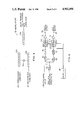
- FIG. 1 is a block diagram showing an embodiment of the disc playback device according to the invention.
- FIG. 2 is a diagram showing an example of the tone volume adjustment and displaying of the tone volume by a key input 88 in FIG. 1;
- FIG. 3 is a diagram showing a format of subcoding data stored in a lead-in area which is located at the innermost portion of a Compact Disc;
- FIG. 4 is a block diagram showing an example of construction of a digital volume 62
- FIG. 5 is a block diagram showing another embodiment of the invention.
- FIG. 6 is still another embodiment of the invention.
- FIG. 1 An embodiment of the invention applied to a Compact Disc player is shown in FIG. 1.
- an optical pickup 10 irradiates laser beam to a Compact Disc 12 and receives laser beam reflected from the Compact Disc 12.
- the received signal is applied to a focus error detection circuit 16 through a preamplifier 14 for detection of a focus error.
- a focus error signal is supplied through a phase compensation circuit 18 and a drive amplifier 20 to a focus actuator (not shown) in the optical pickup 10 in which a focusing control is performed by a focus servo.
- a tracking error signal is supplied through a preamplifier 22, a phase compensation circuit 24 and a drive amplifier 26 to a tracking actuator (not shown) in the optical pickup 10 in which a tracking control is performed by a tracking servo.
- the tracking error signal is also supplied through a phase compensation circuit 28 and a drive amplifier 30 to a feed motor 32 in which a feed control is performed by a feed servo.
- a high frequency signal (HF signal) recorded on the disc 12 which has been detected by the optical pickup 10 is applied to a digital IC 36 through an HF amplifier 34.
- the HF signal is wave-shaped by a digitizing circuit 38 for subsequent digital processing and thereafter is compared in a comparison circuit 40 with a reference frequency from a voltage-controlled oscillator ("VCO") 42.
- VCO voltage-controlled oscillator
- the output of the comparison circuit 40 is used for controlling a disc motor 48 through a constant linear velocity (“CLV”) servo circuit 44 and a drive amplifier 46 so as to control the disc 12 at a constant linear velocity.
- CLV constant linear velocity
- a servo sequence controller 50 is used for sequence-controlling the focus servo, tracking servo, feed servo and disc rotation servo.
- the signal reproduced from the disc is eight-to-fourteen modulation ("EFM") demodulated by an EFM demodulation circuit 52 and thereafter is once stored in a random access memory (“RAM”) 54 and is subjected to C1 and C2 error correction by a C1 and C2 error correction circuit 56.
- the signal stored in the RAM 54 is sequentially read out by an accurate time interval determined by a RAM control circuit 58.
- the read out data is subjected to data interpolation and data muting according to necessity by a data interpolation and muting circuit 60 and thereafter its volume is adjusted by a digital volume 62.
- the data which has thus been adjusted in volume is converted to an analog signal by a digital-to-analog converter 64 and thereafter is distributed to left and right channels by sample-hold circuits 66 and 68.
- the distributed signals are supplied to output terminals 78 and 80 through low-pass filters 70 and 72 and amplifiers 74 and 76.
- a synchronizing signal separation circuit 82 separates a synchronizing signal from the signal reproduced from the disc and a subcode demodulation circuit 84 extracts a subcode from the signal reproduced from the disc.
- a control circuit 86 controls the above described component parts when a key input 88 is operated by the operator for displaying a music number, time data and other information in accordance with the extracted subcode by display device 90, and controls operation of a disc tray by driving a loading motor 94 through a drive amplifier 92.
- the control circuit 86 peforms also the tone volume control according to the invention.
- the control circuit 86 controls the digital volume 62 to adjust the tone volume of the reproduced signal to a volume corresponding to the listener's tone volume adjusting operation.
- the tone volume data set by the operation of the key input 88 and identifying data of the disc 12 are stored in a non-volatile RAM 93. The storage of this set tone volume data and disc identifying data is made for each individual disc and is not erased even after cutting off the electric power source.
- the control circuit 86 identifies the disc 12 when it has been loaded in the disc playback device and, if the set tone volume data of this particular disc has already been stored, reads out the set tone volume data from the non-volatile RAM 93 and controls the digital volume 62 in accordance with the read out tone volume data. An automatic adjustment of the tone volume is made by this control. If the disc 12 loaded in the disc playback device is not identified to be any known disc, this means that the disc 12 is a new disc whose tone volume has not been stored yet and, in this case, the digital volume 62 is set to e.g., gain 1.
- the tone volume adjustment can be made by operating the key input 88 and the set tone volume data and disc identifying data are stored for the first time in the non-volatile RAM 93. From next time the disc 12 is played, the tone volume is controlled in accordance with the newly stored data in the non-volatile RAM 93.
- contents of the non-volatile RAM 93 can be rewritten by operation of the input key 88 and the rewritten data constitutes new set tone volume data.
- the tone volume adjustment is made by adjusting a tone volume setter of the key input 88 under condition that the volume control of the main amplifier is set at a predetermined position and listening to the volume of tone sounded from loudspeakers. If the Compact Disc player has a terminal for a headphone equipment, the tone volume adjustment can be made without being affected by the volume control of the main amplifier by adjusting the tone volume while listening to the tone sounded by the headphone equipment.
- the key input 88 includes a button 94 for increasing the tone volume, a button 96 for decreasing of the tone volume and an indicator 98 indicating the adjusted tone volume.
- the tone volume is increased in proportion to the number of times the button 94 is depressed or as the button 96 is depressed, the tone volume is decreased in proportion to the number of times the button 96 is depressed.
- the digital volume 62 is controlled to set desired tone volume data and this set tone volume data is stored in the non-volatile RAM 93 and also indicated by the indicator 98.
- the indication of the set tone volume data is for example "0" at a gain 1 and increases to "+1", "+2", “+3" . .
- the indicator 98 indicates the set tone volume data stored in the non-volatile RAM 93.
- the indication of the indicator 98 therefore enables the listener to judge whether the tone volume has already been set with respect to this disc or not (i.e., the indication is "0" if the tone volume has not been set yet). Even for a disc in which the tone volume has already been set, the set tone volume data can be changed and the contents stored in the non-volatile RAM 93 can be rewritten by manipulating the buttons 94 and 96.
- the tone volume adjusting operation causes the set tone volume data to be stored automatically in the non-volatile RAM 93.
- a memory button may be provided additionally in the key input 88 and storing of the set tone volume data in the non-volatile RAM 92 may be made by depressing this memory button only when the listener desires to store the set tone volume data.
- the tone volume adjusting operation causes the digital volume 62 to be controlled to perform the tone volume adjustment but the set tone volume data is not stored in the non-volatile RAM 93 unless the memory button is depressed so that the set tone volume data is not maintained until the disc is played next time.
- a disc loaded in the disc playback device can be identified in the following various manners:
- this Q-subcode may be utilized for identifying the disc.
- the digital volume 62 performs tone volume adjustment by multiplying digital data obtained by digitizing data reproduced from the disc 12 with set tone volume data (digital data).
- FIG. 4 shows an example of such digital volume 62.
- Digital data (serial data) obtained by digitizing the data reproduced from the disc 12 is held by a shift register 100 and set tone volume data (serial data) supplied from the control circuit 86 is held by a shift register 102.
- These data are multiplied with each other by a multiplier 104 and the result of the multiplication is provided as serial data through a shift register 106.
- the set tone volume data is repeatedly used each time the reproduced data arrives.
- serial reproduced data and the serial set tone volume data may be multiplied with each other after converting them to parallel data and the result of the multiplication may be converted to serial data again for providing it as the volume controlled reproduced data.
- the tone volume control is performed before the reproduced signal is divided into left and right channel signals so that this arrangement is advantageous in that it requires only a single circuit (i.e., the digital volume 62) for effecting the tone volume control.
- the tone volume control may be performed after the digital-to-analog conversion.
- FIG. 5 shows such embodiment.
- Amplifiers 74' and 76' are constructed of VCAs (voltage-controlled amplifiers) and these amplifiers 74' and 76' are controlled by analog voltages obtained by converting the set tone volume data to analog data by a digital-to-analog converter 108.
- analog electronic volumes (resistance ladder type ones) 110 and 112 may be inserted in the left and right channels as shown in FIG. 6 to control the tone volume directly with control data (digital signal) supplied from the control circuit 86.
- the invention can be applied also to control of a digital or analog tone volume of a video disc.
- Control codes such as a chapter and frame number are recorded on a video disc by utilizing the vertical blanking period.
- a product number, e.g., of a disc recorded in the Users Code may be utilized for identification of the disc.
Abstract
Description
Claims (3)
Applications Claiming Priority (2)
| Application Number | Priority Date | Filing Date | Title |
|---|---|---|---|
| JP61-111181 | 1986-05-15 | ||
| JP61111181A JP2629173B2 (en) | 1986-05-15 | 1986-05-15 | Disk playback device |
Publications (1)
| Publication Number | Publication Date |
|---|---|
| US4962494A true US4962494A (en) | 1990-10-09 |
Family
ID=14554545
Family Applications (1)
| Application Number | Title | Priority Date | Filing Date |
|---|---|---|---|
| US07/048,301 Expired - Lifetime US4962494A (en) | 1986-05-15 | 1987-05-11 | Optical disk playback device having automatic volume control |
Country Status (2)
| Country | Link |
|---|---|
| US (1) | US4962494A (en) |
| JP (1) | JP2629173B2 (en) |
Cited By (11)
| Publication number | Priority date | Publication date | Assignee | Title |
|---|---|---|---|---|
| US5172358A (en) * | 1989-03-08 | 1992-12-15 | Yamaha Corporation | Loudness control circuit for an audio device |
| US5206740A (en) * | 1990-05-28 | 1993-04-27 | Pioneer Electronic Corporation | Video disk player capable of providing normal image reproduction of an external video signal as well as a video signal stored on a disk |
| US5237553A (en) * | 1990-05-24 | 1993-08-17 | Matsushita Electric Industrial Co. | Data recording and reproducing apparatus having a plurality of operating modes |
| US5271011A (en) * | 1992-03-16 | 1993-12-14 | Scientific-Atlanta, Inc. | Digital audio data muting system and method |
| US5359580A (en) * | 1990-01-09 | 1994-10-25 | Sony Corporation | Method of using a single microprocessor to perform data retrieval and disc reproduction control in a disc reproducing apparatus |
| US5408455A (en) * | 1992-04-08 | 1995-04-18 | Asahi Kogaku Kogyo Kabushiki Kaisha | Control device for head unit having optical head and multiple magnetic heads |
| US5452279A (en) * | 1992-03-23 | 1995-09-19 | Kabushiki Kaisha Toshiba | Information recording/reproducing apparatus for recording and reproducing information in accordance with mark interval recording scheme or mark length recording scheme |
| US5805545A (en) * | 1991-08-14 | 1998-09-08 | Pioneer Electronic Corporation | Midi standards recorded information reproducing device with repetitive reproduction capacity |
| US20020051093A1 (en) * | 2000-10-27 | 2002-05-02 | Haruhiko Fujii | Television apparatus |
| US20050069280A1 (en) * | 2003-09-29 | 2005-03-31 | Inventec Corporation | Method of controlling multimedia audio and video playback |
| US20070022464A1 (en) * | 2005-06-14 | 2007-01-25 | Thx, Ltd. | Content presentation optimizer |
Families Citing this family (2)
| Publication number | Priority date | Publication date | Assignee | Title |
|---|---|---|---|---|
| JPH0752553B2 (en) * | 1986-10-01 | 1995-06-05 | パイオニア株式会社 | Recording medium playback device |
| JP4855207B2 (en) * | 2006-10-17 | 2012-01-18 | ローム株式会社 | Volume control apparatus, method, audio signal amplification circuit and electronic apparatus using the same |
Citations (13)
| Publication number | Priority date | Publication date | Assignee | Title |
|---|---|---|---|---|
| US3430215A (en) * | 1964-07-13 | 1969-02-25 | Burroughs Corp | Automatic gain level stepping system |
| US3843850A (en) * | 1970-06-26 | 1974-10-22 | Victor Co Ltd | Four channel record reproducing apparatus with muting of speakers not used for stereo or monaural records |
| US3848092A (en) * | 1973-07-02 | 1974-11-12 | R Shamma | System for electronic modification of sound |
| US4476499A (en) * | 1980-07-29 | 1984-10-09 | Universal Pioneer Corporation | Video disc recording and reproducing system |
| US4484237A (en) * | 1981-01-14 | 1984-11-20 | Nippon Gakki Seizo Kabushiki Kaisha | Apparatus for automatically setting the optimum performance characteristics of a tape recorder |
| US4554599A (en) * | 1982-06-21 | 1985-11-19 | Fujitsu Ten Limited | Cassette tape reproduction control arrangement |
| US4558464A (en) * | 1983-06-10 | 1985-12-10 | General Instrument Corporation | Address-programmable CATV converter |
| US4564867A (en) * | 1980-07-24 | 1986-01-14 | Universal Pioneer Corporation | Video disc recording and reproducing device for video discs having recognition signal indicative of content of associated program signal |
| US4630231A (en) * | 1983-01-31 | 1986-12-16 | Victor Company Of Japan, Ltd. | Control program signal demodulating device |
| US4672472A (en) * | 1984-02-13 | 1987-06-09 | Victor Company Of Japan, Ltd. | Playback apparatus for audiovisual disc records |
| US4698695A (en) * | 1984-09-14 | 1987-10-06 | Pioneer Electronic Corporation | Recording disk data playback apparatus |
| US4698670A (en) * | 1986-07-14 | 1987-10-06 | Westinghouse Electric Corp. | Cable stereo apparatus |
| US4779252A (en) * | 1984-07-02 | 1988-10-18 | U.S. Philips Corp. | Apparatus for automatically reproducing preferred selection from a record carrier |
Family Cites Families (1)
| Publication number | Priority date | Publication date | Assignee | Title |
|---|---|---|---|---|
| JPS60157703A (en) * | 1984-01-27 | 1985-08-19 | Pioneer Electronic Corp | Cassette tape reproducer |
-
1986
- 1986-05-15 JP JP61111181A patent/JP2629173B2/en not_active Expired - Fee Related
-
1987
- 1987-05-11 US US07/048,301 patent/US4962494A/en not_active Expired - Lifetime
Patent Citations (13)
| Publication number | Priority date | Publication date | Assignee | Title |
|---|---|---|---|---|
| US3430215A (en) * | 1964-07-13 | 1969-02-25 | Burroughs Corp | Automatic gain level stepping system |
| US3843850A (en) * | 1970-06-26 | 1974-10-22 | Victor Co Ltd | Four channel record reproducing apparatus with muting of speakers not used for stereo or monaural records |
| US3848092A (en) * | 1973-07-02 | 1974-11-12 | R Shamma | System for electronic modification of sound |
| US4564867A (en) * | 1980-07-24 | 1986-01-14 | Universal Pioneer Corporation | Video disc recording and reproducing device for video discs having recognition signal indicative of content of associated program signal |
| US4476499A (en) * | 1980-07-29 | 1984-10-09 | Universal Pioneer Corporation | Video disc recording and reproducing system |
| US4484237A (en) * | 1981-01-14 | 1984-11-20 | Nippon Gakki Seizo Kabushiki Kaisha | Apparatus for automatically setting the optimum performance characteristics of a tape recorder |
| US4554599A (en) * | 1982-06-21 | 1985-11-19 | Fujitsu Ten Limited | Cassette tape reproduction control arrangement |
| US4630231A (en) * | 1983-01-31 | 1986-12-16 | Victor Company Of Japan, Ltd. | Control program signal demodulating device |
| US4558464A (en) * | 1983-06-10 | 1985-12-10 | General Instrument Corporation | Address-programmable CATV converter |
| US4672472A (en) * | 1984-02-13 | 1987-06-09 | Victor Company Of Japan, Ltd. | Playback apparatus for audiovisual disc records |
| US4779252A (en) * | 1984-07-02 | 1988-10-18 | U.S. Philips Corp. | Apparatus for automatically reproducing preferred selection from a record carrier |
| US4698695A (en) * | 1984-09-14 | 1987-10-06 | Pioneer Electronic Corporation | Recording disk data playback apparatus |
| US4698670A (en) * | 1986-07-14 | 1987-10-06 | Westinghouse Electric Corp. | Cable stereo apparatus |
Cited By (18)
| Publication number | Priority date | Publication date | Assignee | Title |
|---|---|---|---|---|
| US5172358A (en) * | 1989-03-08 | 1992-12-15 | Yamaha Corporation | Loudness control circuit for an audio device |
| US5535184A (en) * | 1990-01-09 | 1996-07-09 | Sony Corporation | Reproducing apparatus having a single microprocessor to perform data retrieval disc reproduction control |
| US5359580A (en) * | 1990-01-09 | 1994-10-25 | Sony Corporation | Method of using a single microprocessor to perform data retrieval and disc reproduction control in a disc reproducing apparatus |
| US5502695A (en) * | 1990-01-09 | 1996-03-26 | Sony Corporation | Reproducing apparatus having a single microprocessor to perform data retrieval and disc reproduction control |
| US5237553A (en) * | 1990-05-24 | 1993-08-17 | Matsushita Electric Industrial Co. | Data recording and reproducing apparatus having a plurality of operating modes |
| US5206740A (en) * | 1990-05-28 | 1993-04-27 | Pioneer Electronic Corporation | Video disk player capable of providing normal image reproduction of an external video signal as well as a video signal stored on a disk |
| US5805545A (en) * | 1991-08-14 | 1998-09-08 | Pioneer Electronic Corporation | Midi standards recorded information reproducing device with repetitive reproduction capacity |
| US5271011A (en) * | 1992-03-16 | 1993-12-14 | Scientific-Atlanta, Inc. | Digital audio data muting system and method |
| US5452279A (en) * | 1992-03-23 | 1995-09-19 | Kabushiki Kaisha Toshiba | Information recording/reproducing apparatus for recording and reproducing information in accordance with mark interval recording scheme or mark length recording scheme |
| US5513159A (en) * | 1992-04-08 | 1996-04-30 | Asahi Kogaku Kogyo Kabushiki Kaisha | Device for selecting magnetic head to be operated together with an optical head |
| US5592447A (en) * | 1992-04-08 | 1997-01-07 | Asahi Kogaku Kogyo Kabushiki Kaisha | Control device for head unit having optical head and multiple magnetic heads |
| US5408455A (en) * | 1992-04-08 | 1995-04-18 | Asahi Kogaku Kogyo Kabushiki Kaisha | Control device for head unit having optical head and multiple magnetic heads |
| US20020051093A1 (en) * | 2000-10-27 | 2002-05-02 | Haruhiko Fujii | Television apparatus |
| US7085477B2 (en) * | 2000-10-27 | 2006-08-01 | Funai Electric Co., Ltd. | Television apparatus |
| US20050069280A1 (en) * | 2003-09-29 | 2005-03-31 | Inventec Corporation | Method of controlling multimedia audio and video playback |
| US7391963B2 (en) * | 2003-09-29 | 2008-06-24 | Inventec Corporation | Method of controlling multimedia audio and video playback |
| US20070022464A1 (en) * | 2005-06-14 | 2007-01-25 | Thx, Ltd. | Content presentation optimizer |
| US8482614B2 (en) * | 2005-06-14 | 2013-07-09 | Thx Ltd | Content presentation optimizer |
Also Published As
| Publication number | Publication date |
|---|---|
| JPS62266768A (en) | 1987-11-19 |
| JP2629173B2 (en) | 1997-07-09 |
Similar Documents
| Publication | Publication Date | Title |
|---|---|---|
| EP0363186B1 (en) | Method for setting a sound recording level | |
| US4893193A (en) | Disc recording medium and apparatus for playback thereof | |
| US5130816A (en) | Method and apparatus for recording and reproducing information including plural channel audio signals | |
| EP0310678B1 (en) | Disc recording/reproducing apparatus and disc recording/reproducing method | |
| EP0277019B1 (en) | Disk playing method and device | |
| US4962494A (en) | Optical disk playback device having automatic volume control | |
| EP0386913A1 (en) | Disc player | |
| US5313011A (en) | Apparatus for carrying out automatic play in synchronism with playback of data recorded on recording medium | |
| EP0331417A2 (en) | Method and apparatus for reproducing picture information | |
| US6343180B1 (en) | Apparatus and method for producing reproduction time of an optical disc | |
| US4961116A (en) | Method of, and apparatus for, facilitating sychronization of recorded audio and video information | |
| EP0497387B1 (en) | Record information reproducing method with content identifiers | |
| EP1400968A2 (en) | Play control method in digital versatile disc player | |
| EP0500391A2 (en) | Apparatus for reproducing information with different scanning modes | |
| US20020101790A1 (en) | Information reproducing apparatus | |
| US4839746A (en) | Information reproduction method for complex and CD disks | |
| US5315578A (en) | Disc recording medium and data recording method | |
| US4873586A (en) | Method and apparatus for reproducing audio and video data from a disk | |
| JP2000235772A (en) | Cd reproducing device | |
| US5105402A (en) | Disc player with manual search function | |
| JPH02101691A (en) | Introduction scanning method | |
| JPH07296511A (en) | Sound volume and quality automatic setting device | |
| JPH04114365A (en) | Disk reproducing device | |
| KR100240334B1 (en) | Recording method of a dvdr system | |
| JPH06202623A (en) | Score display device |
Legal Events
| Date | Code | Title | Description |
|---|---|---|---|
| AS | Assignment |
Owner name: NIPPON GAKKI SEIZO KABUSHIKI KAISHA, 10-1, NAKAZAW Free format text: ASSIGNMENT OF ASSIGNORS INTEREST.;ASSIGNOR:KIMURA, SHIGENOBU;REEL/FRAME:004734/0528 Effective date: 19870425 |
|
| AS | Assignment |
Owner name: YAMAHA CORPORATION, 10-1, NAKAZAWA-CHO, HAMAMATSU- Free format text: CHANGE OF NAME;ASSIGNOR:NIPPON GAKKI SEIZO KABUSHIKI KAISHA;REEL/FRAME:004884/0367 Effective date: 19880216 Owner name: YAMAHA CORPORATION,JAPAN Free format text: CHANGE OF NAME;ASSIGNOR:NIPPON GAKKI SEIZO KABUSHIKI KAISHA;REEL/FRAME:004884/0367 Effective date: 19880216 |
|
| STCF | Information on status: patent grant |
Free format text: PATENTED CASE |
|
| FPAY | Fee payment |
Year of fee payment: 4 |
|
| FPAY | Fee payment |
Year of fee payment: 8 |
|
| FPAY | Fee payment |
Year of fee payment: 12 |