US4964864A - Heart assist pump - Google Patents
Heart assist pump Download PDFInfo
- Publication number
- US4964864A US4964864A US07/249,830 US24983088A US4964864A US 4964864 A US4964864 A US 4964864A US 24983088 A US24983088 A US 24983088A US 4964864 A US4964864 A US 4964864A
- Authority
- US
- United States
- Prior art keywords
- pump
- rotor
- stator
- blood
- heart
- Prior art date
- Legal status (The legal status is an assumption and is not a legal conclusion. Google has not performed a legal analysis and makes no representation as to the accuracy of the status listed.)
- Expired - Fee Related
Links
Images


Classifications
-
- F—MECHANICAL ENGINEERING; LIGHTING; HEATING; WEAPONS; BLASTING
- F04—POSITIVE - DISPLACEMENT MACHINES FOR LIQUIDS; PUMPS FOR LIQUIDS OR ELASTIC FLUIDS
- F04C—ROTARY-PISTON, OR OSCILLATING-PISTON, POSITIVE-DISPLACEMENT MACHINES FOR LIQUIDS; ROTARY-PISTON, OR OSCILLATING-PISTON, POSITIVE-DISPLACEMENT PUMPS
- F04C13/00—Adaptations of machines or pumps for special use, e.g. for extremely high pressures
- F04C13/001—Pumps for particular liquids
-
- A—HUMAN NECESSITIES
- A61—MEDICAL OR VETERINARY SCIENCE; HYGIENE
- A61M—DEVICES FOR INTRODUCING MEDIA INTO, OR ONTO, THE BODY; DEVICES FOR TRANSDUCING BODY MEDIA OR FOR TAKING MEDIA FROM THE BODY; DEVICES FOR PRODUCING OR ENDING SLEEP OR STUPOR
- A61M60/00—Blood pumps; Devices for mechanical circulatory actuation; Balloon pumps for circulatory assistance
- A61M60/10—Location thereof with respect to the patient's body
- A61M60/122—Implantable pumps or pumping devices, i.e. the blood being pumped inside the patient's body
- A61M60/126—Implantable pumps or pumping devices, i.e. the blood being pumped inside the patient's body implantable via, into, inside, in line, branching on, or around a blood vessel
- A61M60/13—Implantable pumps or pumping devices, i.e. the blood being pumped inside the patient's body implantable via, into, inside, in line, branching on, or around a blood vessel by means of a catheter allowing explantation, e.g. catheter pumps temporarily introduced via the vascular system
-
- A—HUMAN NECESSITIES
- A61—MEDICAL OR VETERINARY SCIENCE; HYGIENE
- A61M—DEVICES FOR INTRODUCING MEDIA INTO, OR ONTO, THE BODY; DEVICES FOR TRANSDUCING BODY MEDIA OR FOR TAKING MEDIA FROM THE BODY; DEVICES FOR PRODUCING OR ENDING SLEEP OR STUPOR
- A61M60/00—Blood pumps; Devices for mechanical circulatory actuation; Balloon pumps for circulatory assistance
- A61M60/20—Type thereof
- A61M60/205—Non-positive displacement blood pumps
- A61M60/216—Non-positive displacement blood pumps including a rotating member acting on the blood, e.g. impeller
- A61M60/237—Non-positive displacement blood pumps including a rotating member acting on the blood, e.g. impeller the blood flow through the rotating member having mainly axial components, e.g. axial flow pumps
-
- A—HUMAN NECESSITIES
- A61—MEDICAL OR VETERINARY SCIENCE; HYGIENE
- A61M—DEVICES FOR INTRODUCING MEDIA INTO, OR ONTO, THE BODY; DEVICES FOR TRANSDUCING BODY MEDIA OR FOR TAKING MEDIA FROM THE BODY; DEVICES FOR PRODUCING OR ENDING SLEEP OR STUPOR
- A61M60/00—Blood pumps; Devices for mechanical circulatory actuation; Balloon pumps for circulatory assistance
- A61M60/40—Details relating to driving
- A61M60/403—Details relating to driving for non-positive displacement blood pumps
- A61M60/408—Details relating to driving for non-positive displacement blood pumps the force acting on the blood contacting member being mechanical, e.g. transmitted by a shaft or cable
- A61M60/411—Details relating to driving for non-positive displacement blood pumps the force acting on the blood contacting member being mechanical, e.g. transmitted by a shaft or cable generated by an electromotor
- A61M60/414—Details relating to driving for non-positive displacement blood pumps the force acting on the blood contacting member being mechanical, e.g. transmitted by a shaft or cable generated by an electromotor transmitted by a rotating cable, e.g. for blood pumps mounted on a catheter
-
- A—HUMAN NECESSITIES
- A61—MEDICAL OR VETERINARY SCIENCE; HYGIENE
- A61M—DEVICES FOR INTRODUCING MEDIA INTO, OR ONTO, THE BODY; DEVICES FOR TRANSDUCING BODY MEDIA OR FOR TAKING MEDIA FROM THE BODY; DEVICES FOR PRODUCING OR ENDING SLEEP OR STUPOR
- A61M60/00—Blood pumps; Devices for mechanical circulatory actuation; Balloon pumps for circulatory assistance
- A61M60/10—Location thereof with respect to the patient's body
- A61M60/122—Implantable pumps or pumping devices, i.e. the blood being pumped inside the patient's body
- A61M60/126—Implantable pumps or pumping devices, i.e. the blood being pumped inside the patient's body implantable via, into, inside, in line, branching on, or around a blood vessel
- A61M60/148—Implantable pumps or pumping devices, i.e. the blood being pumped inside the patient's body implantable via, into, inside, in line, branching on, or around a blood vessel in line with a blood vessel using resection or like techniques, e.g. permanent endovascular heart assist devices
-
- F—MECHANICAL ENGINEERING; LIGHTING; HEATING; WEAPONS; BLASTING
- F04—POSITIVE - DISPLACEMENT MACHINES FOR LIQUIDS; PUMPS FOR LIQUIDS OR ELASTIC FLUIDS
- F04C—ROTARY-PISTON, OR OSCILLATING-PISTON, POSITIVE-DISPLACEMENT MACHINES FOR LIQUIDS; ROTARY-PISTON, OR OSCILLATING-PISTON, POSITIVE-DISPLACEMENT PUMPS
- F04C2/00—Rotary-piston machines or pumps
- F04C2/08—Rotary-piston machines or pumps of intermeshing-engagement type, i.e. with engagement of co-operating members similar to that of toothed gearing
- F04C2/10—Rotary-piston machines or pumps of intermeshing-engagement type, i.e. with engagement of co-operating members similar to that of toothed gearing of internal-axis type with the outer member having more teeth or tooth-equivalents, e.g. rollers, than the inner member
- F04C2/107—Rotary-piston machines or pumps of intermeshing-engagement type, i.e. with engagement of co-operating members similar to that of toothed gearing of internal-axis type with the outer member having more teeth or tooth-equivalents, e.g. rollers, than the inner member with helical teeth
- F04C2/1071—Rotary-piston machines or pumps of intermeshing-engagement type, i.e. with engagement of co-operating members similar to that of toothed gearing of internal-axis type with the outer member having more teeth or tooth-equivalents, e.g. rollers, than the inner member with helical teeth the inner and outer member having a different number of threads and one of the two being made of elastic materials, e.g. Moineau type
Definitions
- This invention relates to blood pumps, particularly to a temporary circulatory assist pump adapted for insertion into the vascular system of a patient to provide temporary circulatory assistance for an infarcted left or right ventricle of the heart.
- Heart disease Death and disability from heart disease are most commonly due to the pumping inadequacy of an infarcted left or right ventricle.
- the heart of a patient suffering from this condition functions in all other respects but does not provide sufficient blood flow to keep the patient alive.
- a patient suffering from this condition would require major surgery to maintain the heart and provide sufficient blood flow for the patient.
- a high capacity intravascular blood pump is disclosed.
- the pump is inserted into the heart through the femoral artery and driven via a flexible cable from an external power source.
- the drive cable is contained within a catheter attached to the pump.
- the pump is rotated in the range of 10,000-20,000 rpm to produce blood flow on the order of about 4 liters per minute.
- U.S. Pat. No. 3,505,987 discloses a counterpulsation system for aiding coronary circulation.
- the system includes an expandable impeller located within the aorta of a patient.
- the impeller is expanded and contracted while simultaneously being reciprocated within the aorta and synchronized with the pumping activity of the heart for reducing aortic pressure during systole and increasing aortic pressure during diastole.
- U.S. Pat. No. 3,667,069 discloses an implantable jet pump for replacing or assisting the right heart.
- the jet pump comprises an elongated tubular structure including an upstream driving nozzle from which a driving flow of arterial blood under pressure is ejected into a suction nozzle creating its own reduced pressure to cause venous blood to be sucked into and admixed with the driving flow for distribution to the pulmonary circulation system.
- the jet pump may be powered by blood pumped from the left heart or an artificial replacement for the left heart.
- U.S. Pat. No. 4,051,840 discloses an aortic patch which may be surgically implanted in the thoracic aorta.
- the aortic patch is systematically inflated and deflated to generate pressure waves in the blood stream.
- the pressure waves assist the heart by augmenting &:he circulation of the blood to the body.
- the present invention is directed to a miniature temporary circulatory assist pump adapted to be inserted in the heart of the patient for circulatory assistance.
- the pump is introduced into the left ventricle of the heart by a catheter passed through the arterial system of the patient.
- the pump utilizes the moineau pump principle to deliver large volumes of blood at relatively low rpm and pressure.
- a venturi tube arrangement is utilized to pressurize the blood flow to create a suction effect for increasing the volume of blood pumped through the circulatory system of the patient.
- FIG. 1 is an illustrative view of a section of a human heart depicting the preferred position of the pump of the invention in the left ventricle of the heart;
- FIG. 2 is a schematic view illustrating the insertion of the pump of the invention through the femoral artery of a patient;
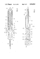
- FIG. 3 is a partial sectional view of the pump of the invention.
- FIG. 4 is a partial sectional view of an alternate embodiment of the pump of the invention.
- FIG. 5 is a partial sectional view of an alternate embodiment of the pump of the invention.
- FIG. 6 is an illustrative view of a section of a human heart depicting an alternate embodiment of the pump of the invention.
- the blood pump of the invention is shown inserted in the left ventricle 10 of the heart 12.
- the blood pump is generally identified by the reference numeral 14 and is carried at the forward end of a catheter 16.
- Access to the heart 12 is provided in the preferred embodiment through the femoral artery 18. This is the preferred insertion point, however, it is understood that the heart 12 may be accessed through other arteries or other surgical means.
- the blood pump 14 is located in the left ventricle 10. However, in some circumstances it may be desirable to locate the blood pump 14 in the right ventricle 20. Access to the right ventricle 20 may be provided through the pulmonary artery 22. In operation, the intake end of the blood pump 14 shown in FIG.
- the outlet or discharge end of the blood pump 14 is located in the aorta 24.
- the blood pump 14 thus extends partially into the left ventricle 10 through the heart valve 26. Blood is pumped through the blood pump 14 from the left ventricle 10 in the direction of the arrows 28 into the aorta 24.
- the pump 14 is provided with a suction tube 15 mounted to the intake end of the pump 14.
- the suction tube 15 is formed of a flexible, elastomeric material and projects from the intake end of the pump 14 into the left ventricle 10 of the heart 12 as shown in FIG. 6.
- the pump 14 is shown in greater detail.
- the pump 14 is driven by a flexible drive shaft 30 which extends through the catheter 16.
- the drive shaft 30 is driven by a motor 31 located outside the patient's body, as best shown in FIG. 2.
- the pump 14 is secured to the distal end of the catheter 16.
- the pump 14 and catheter 16 are guided through the femoral artery to the left ventricle 10.
- the pump 14 is positioned in the left ventricle 10 of the heart.
- the pump 14 is positioned so that the intake end 32 extends through the heart valve 26 into the left ventricle 10.
- the discharge end 34 of the pump 14 is positioned outside the left ventricle 10 so that pumped blood is discharged into the aorta 24 as shown in FIG. 1.
- the pump 14 comprises a substantially cylindrical elongate body 36.
- the intake end 32 of the body 36 presents a cone-like profile blunted at its forward end so that it may easily be inserted into the left ventricle 10 past the heart valve 26 without damaging the heart valve or any of the heart tissue.
- the intake end 32 includes a number of intake ports 38 so that blood collected in the left ventricle 10 may flow freely into the pump 14.
- Housed within the housing 36 is a stator 40 and a rotor 42.
- the stator and rotor operate utilizing the moineau pumping principal which uses rotary motion to move a seal continuously through the stator 40 for pumping blood through the pump 14.
- the stator 40 is fabricated of resilient material and the rotor 42 is fabricated of stainless steel material formed in a helical shape.
- the rotor 42 is connected to the drive shaft 30 by a flexible joint 44 which permits the end of the rotor 42 to move through a helical path as the rotor 42 is driven by the drive shaft 30.
- a discharge nozzle 46 is provided for directing the pumped blood to the intake end 50 of a venturi tube 48. It will be observed that the discharge end of the discharge nozzle 46 extends into the intake end 50 of the venturi tube 48. An annular space 52 is thus defined between the discharge end 49 of the discharge nozzle 46 and the intake end 50 of the venturi tube 48.
- the intake end 50 of the venturi tube 48 is open to a chamber 54 formed within the housing 36 about the discharge nozzle 46 and venturi tube 48. Blood collected in the left ventricle 10 enters the chamber 54 through a plurality of ports 56.
- blood from the left ventricle 10, in the embodiment of FIG. 3, is sucked through the intake 32 and pumped into the discharge nozzle 46 by rotation of the rotor 42.
- the blood is pressurized as it is pumped through the discharge nozzle 46 by restricting the discharge area of the discharge nozzle 46 and thereby jetting the blood into the venturi tube 48.
- the restriction in the discharge nozzle 46 and venturi tube 48 are designed to cause the pumped blood passing through the discharge nozzle 48 to attain venturi velocities which can be precisely determined.
- venturi velocities negative pressure is produced in the annular space 52 around the discharge end 49 of the discharge nozzle 46.
- FIG. 4 an alternate embodiment of the pump of the invention generally identified by the reference numeral 60 is shown.
- the pump 60 utilizes the same moineau type pumping principal to move blood through the pump, however, the stator and rotor are modified somewhat as will be described in greater detail.
- the pump 60 is positioned in the left ventricle 10 of the heart 12 by the catheter 16 in the same manner as previously described with regard to pump 14.
- the pump 60 is very similar to the pump 14 and therefore like reference numerals are used to indicate like elements.
- the stator 62 of the pump 60 is provided with multiple suction intake ports which discharge into a common discharge duct.
- the stator 62 is fabricated of a resilient material and includes three intake ports 64, 66 and 68.
- the intake port 64 is located at the forward end of the stator 64.
- the intake ports 66 and 68 are located on the cylindrical body of the stator 62 and are formed by drilling a hole at an angle through the body 62 opening into a rotor cavity.
- Each of the intake ports 64, 66 and 68 communicate with separate rotor cavities 70, 72 and 74, respectively, which form the rotor cavity of the pump 60.
- the rotor cavities 70, 72 and 74 include outlet ports 76, 78 and 80 which discharge into a common discharge duct 82.
- the rotor cavities 70, 72 and 74 are separated by shaft stabilizers 84 which support and seal about the rotor 86 within the rotor cavity of the pump 60.
- the rotor 86 is driven by drive shaft 88 which is connected to the drive motor 31.
- the drive shaft 88 is connected to the rotor 86 by a flexible joint 90 which permits the end of the rotor 86 to move through a slight orbital path as the rotor 86 is rotated by the drive shaft 88.
- the pump 60 shown in FIG. 4 comprises a single rotor and stator having multiple inlet and outlet ports so that a greater volume of blood is pumped through the pump 60 with each revolution of the rotor 86.
- the rotor cavities 70, 72 and 74 are configured for separate and individual pumping upon rotation of the rotor 86.
- rotation of the rotor 86 by the drive shaft 88 moves a seal continuously through each of the cavities 70, 72 and 74.
- blood enters the rotor cavities 70, 72 and 74 through the intake ports 64, 66 and 68.
- Each rotation of the rotor 86 sweeps the rotor cavities 70, 72 and 74 and forces the blood through the outlet ports 76, 78 and 80 into the common discharge duct 82 and then into the conduit 92 which discharges into the aorta 24 through outlet ports 93.
- the pump 100 is substantially identical to the pump 60 shown in FIG. 4. It is placed in the left ventricle 10 of the heart 12 substantially the same manner as previously described.
- the pump 100 comprises a stator 102 which houses a rotor 104.
- the stator 102 is fabricated of resilient material so that a rotating seal is formed with the helical shaped stainless steel rotor 104.
- the stator 102 includes a helical rotor cavity 101 having an intake port 106 and an outlet port 108.
- the rotor 104 is connected to a drive shaft 110 by a flexible joint 112.
- the drive shaft 110 is centrally positioned within the discharge conduit 114 of the pump 100 by a shaft stabilizer 116.
- the pump 100 draws blood from the left ventricle 10 through the intake port 106.
- a moving seal is formed with the stator 102 so that blood is pumped through the helical cavity 102 and discharged into the conduit 114.
- the shaft stabilizer 116 includes a plurality of apertures 118 extending therethrough permitting blood to flow past the shaft stabilizer 116 to be discharged into the aorta 24 through outlet ports 120 located in the rear wall of the the pump 100.
- the heart assist pump of the present invention utilizes the geometrical relationship between the rotor and the stator to pump blood from the heart of a patient.
- the rotor and stator are in contact with each other at two points which form two sealing lines over the length of the rotor and stator.
- the rotor has a single helix shape and is typically fabricated of a metallic material.
- the stator is formed as a double helix and is typically fabricated of an elastomer. The interference or compression fit between the rotor and stator creates a series of sealed chambers or cavities. Pumping action is achieved by the rotor driven eccentrically within the stator.
- Fluid such as blood
- the cavity formed at the inlet end of the pump and progresses within the cavity and is discharged through the outlet end. Because the force generating sections of the rotor and stator are smooth and curved, very little surface area is available for contact stress. In cross-section, the stator is obround while the rotor in cross-section is circular. The dissimilarity of the shapes between the rotor and stator creates wedge-shaped cavities within the pump unit. Rotation exerts a progressive displacement of the wedge-shaped cavities. In doing so, blood seeks an exit without turbulence. Thus, the volume of blood flowing through the pump of the invention is directly proportional to rotor speed.
- Blood contained in the sealed cavities which are formed as the rotor turns is displaced axially and with complete continuity from the suction or inlet end to the outlet end of the pump. Despite the fact that the rotor rotates, no turbulence is produced.
- the constant volume of the enclosed cavities eliminates pressurizing forces and thus a low surge pumping action is accomplished which is ideal for shear sensitive materials.
- the pump of the present disclosure is self-priming and non-cavitating.
- the prime creates the suction movement of material without which the material cannot be moved.
- a progressive cavity pump of the type disclosed herein is always in prime.
- Impeller pumps however, loose prime and over-accelerate. Over-acceleration can produce cavitation within the pump, resulting in pockets of partial vacuums in the blood flow, causing the separation of blood parts.
- Blood being a non-Newtonian fluid, is more susceptible to such spontaneous, non-linear viscoelastic behavior. In viscometric fluid motion, each fluid element is undergoing a steady sheering motion. However, in non-linear viscoelastic responses, the symmetry of a simple flow is replaced by functional stress factors and turbulence with loss of efficiencies. More simply stated, the heart assist pump of the present disclosure maintains a nonturbulent, constant volume of blood in the enclosed cavities with no pressurizing forces. The low surge action of the pump disclosed herein produces an ideal flow with very predictable Newtonian flow regimen
- the pump of the present invention is dimensioned to provide blood flow of three to four liters per minute, yet it operates at a speed of approximately 2,500 rpm to produce the required blood flow to sustain a patient while the patient's heart is resting and repairing itself.
- the pump of the present disclosure does not utilize propellers or turbine blades to pump blood.
- the moineau type pump of the present invention substantially reduces or eliminates the risk of hemolysis.
- the blood is pumped through the pump of the invention by a rotating seal formed between the stator and helical rotor as described above. The blood is thus pushed through the stator cavity with each rotation of the rotor. No shear forces are developed that would damage the blood cells as the blood is pumped through the pump and discharged into the aorta of the patient.
Abstract
Description
Claims (5)
Priority Applications (6)
| Application Number | Priority Date | Filing Date | Title |
|---|---|---|---|
| US07/249,830 US4964864A (en) | 1988-09-27 | 1988-09-27 | Heart assist pump |
| AU63699/90A AU641430B2 (en) | 1988-09-27 | 1990-10-02 | Heart assist pump |
| AT90311063T ATE137980T1 (en) | 1988-09-27 | 1990-10-09 | CARDIAC SUPPORT PUMP |
| EP90311063A EP0480101B1 (en) | 1988-09-27 | 1990-10-09 | Heart assist pump |
| DE69027029T DE69027029T2 (en) | 1988-09-27 | 1990-10-09 | Cardiac assist pump |
| US07/601,881 US5112349A (en) | 1988-09-27 | 1990-10-22 | Heart assist pump |
Applications Claiming Priority (1)
| Application Number | Priority Date | Filing Date | Title |
|---|---|---|---|
| US07/249,830 US4964864A (en) | 1988-09-27 | 1988-09-27 | Heart assist pump |
Publications (1)
| Publication Number | Publication Date |
|---|---|
| US4964864A true US4964864A (en) | 1990-10-23 |
Family
ID=22945204
Family Applications (2)
| Application Number | Title | Priority Date | Filing Date |
|---|---|---|---|
| US07/249,830 Expired - Fee Related US4964864A (en) | 1988-09-27 | 1988-09-27 | Heart assist pump |
| US07/601,881 Expired - Fee Related US5112349A (en) | 1988-09-27 | 1990-10-22 | Heart assist pump |
Family Applications After (1)
| Application Number | Title | Priority Date | Filing Date |
|---|---|---|---|
| US07/601,881 Expired - Fee Related US5112349A (en) | 1988-09-27 | 1990-10-22 | Heart assist pump |
Country Status (5)
| Country | Link |
|---|---|
| US (2) | US4964864A (en) |
| EP (1) | EP0480101B1 (en) |
| AT (1) | ATE137980T1 (en) |
| AU (1) | AU641430B2 (en) |
| DE (1) | DE69027029T2 (en) |
Cited By (87)
| Publication number | Priority date | Publication date | Assignee | Title |
|---|---|---|---|---|
| US5092844A (en) * | 1990-04-10 | 1992-03-03 | Mayo Foundation For Medical Education And Research | Intracatheter perfusion pump apparatus and method |
| EP0480101A1 (en) * | 1988-09-27 | 1992-04-15 | American Biomed, Inc. | Heart assist pump |
| US5147388A (en) * | 1990-03-08 | 1992-09-15 | Kenji Yamazaki | Auxiliary artificial heart of the embedded-in-body type |
| US5163910A (en) * | 1990-04-10 | 1992-11-17 | Mayo Foundation For Medical Education And Research | Intracatheter perfusion pump apparatus and method |
| US5300112A (en) * | 1992-07-14 | 1994-04-05 | Aai Corporation | Articulated heart pump |
| US5376114A (en) * | 1992-10-30 | 1994-12-27 | Jarvik; Robert | Cannula pumps for temporary cardiac support and methods of their application and use |
| EP0764448A2 (en) * | 1995-09-22 | 1997-03-26 | United States Surgical Corporation | Cardiac support device |
| US5851174A (en) * | 1996-09-17 | 1998-12-22 | Robert Jarvik | Cardiac support device |
| US5947892A (en) * | 1993-11-10 | 1999-09-07 | Micromed Technology, Inc. | Rotary blood pump |
| US5965089A (en) * | 1996-10-04 | 1999-10-12 | United States Surgical Corporation | Circulatory support system |
| WO1999051286A1 (en) * | 1998-04-02 | 1999-10-14 | Scimed Life Systems, Inc. | System for treating congestive heart failure |
| US6245007B1 (en) | 1999-01-28 | 2001-06-12 | Terumo Cardiovascular Systems Corporation | Blood pump |
| US6508787B2 (en) * | 1995-09-26 | 2003-01-21 | Fraunhofer-Gesellschaft Zur Foerderung Der Angewandten Forschung E.V. | System for actively supporting the flow of body fluids |
| US20040059276A1 (en) * | 2002-09-20 | 2004-03-25 | Flomedica, Inc. | Intra-aortic renal delivery catheter |
| US6749598B1 (en) | 1999-01-11 | 2004-06-15 | Flowmedica, Inc. | Apparatus and methods for treating congestive heart disease |
| US6994700B2 (en) | 2002-09-20 | 2006-02-07 | Flowmedica, Inc. | Apparatus and method for inserting an intra-aorta catheter through a delivery sheath |
| US7122019B1 (en) | 2000-11-28 | 2006-10-17 | Flowmedica Inc. | Intra-aortic renal drug delivery catheter |
| US20070004959A1 (en) * | 2003-05-11 | 2007-01-04 | Michel Carrier | Blood pump with frusto-conical bearing structure |
| US7329236B2 (en) | 1999-01-11 | 2008-02-12 | Flowmedica, Inc. | Intra-aortic renal drug delivery catheter |
| US7364566B2 (en) | 2002-09-20 | 2008-04-29 | Flowmedica, Inc. | Method and apparatus for intra-aortic substance delivery to a branch vessel |
| US7481803B2 (en) | 2000-11-28 | 2009-01-27 | Flowmedica, Inc. | Intra-aortic renal drug delivery catheter |
| US20090149695A1 (en) * | 2003-09-02 | 2009-06-11 | Pulsecath B.V. | Catheter pump, catheter and fittings therefore and methods of using a catheter pump |
| US7585836B2 (en) | 2004-05-14 | 2009-09-08 | Goodson Iv Harry Burt | Bi-lateral local renal delivery for treating congestive heart failure and for BNP therapy |
| US7766961B2 (en) | 2003-06-05 | 2010-08-03 | Angio Dynamics, Inc. | Systems and methods for performing bi-lateral interventions or diagnosis in branched body lumens |
| US7771401B2 (en) | 2006-06-08 | 2010-08-10 | Angiodynamics, Inc. | Selective renal cannulation and infusion systems and methods |
| US7780628B1 (en) | 1999-01-11 | 2010-08-24 | Angiodynamics, Inc. | Apparatus and methods for treating congestive heart disease |
| US7841976B2 (en) | 2006-03-23 | 2010-11-30 | Thoratec Corporation | Heart assist device with expandable impeller pump |
| US7914503B2 (en) | 2002-09-20 | 2011-03-29 | Angio Dynamics | Method and apparatus for selective material delivery via an intra-renal catheter |
| US7927068B2 (en) | 2004-09-17 | 2011-04-19 | Thoratec Corporation | Expandable impeller pump |
| US7993325B2 (en) | 2002-09-20 | 2011-08-09 | Angio Dynamics, Inc. | Renal infusion systems and methods |
| US7998054B2 (en) | 1997-10-09 | 2011-08-16 | Thoratec Corporation | Implantable heart assist system and method of applying same |
| EP2388029A1 (en) * | 2010-05-17 | 2011-11-23 | ECP Entwicklungsgesellschaft mbH | Pump array |
| US8118724B2 (en) | 2003-09-18 | 2012-02-21 | Thoratec Corporation | Rotary blood pump |
| US20120101455A1 (en) * | 2009-04-29 | 2012-04-26 | Ecp Entwicklungsgesellschaft Mbh | Shaft arrangement having a shaft which extends within a fluid-filled casing |
| US8449443B2 (en) | 2008-10-06 | 2013-05-28 | Indiana University Research And Technology Corporation | Active or passive assistance in the circulatory system |
| US8485961B2 (en) | 2011-01-05 | 2013-07-16 | Thoratec Corporation | Impeller housing for percutaneous heart pump |
| US8518011B2 (en) | 2004-03-04 | 2013-08-27 | Angiodynamics, Inc. | Sheath for use in peripheral interventions |
| US8535211B2 (en) | 2009-07-01 | 2013-09-17 | Thoratec Corporation | Blood pump with expandable cannula |
| US8591393B2 (en) | 2011-01-06 | 2013-11-26 | Thoratec Corporation | Catheter pump |
| US8597170B2 (en) | 2011-01-05 | 2013-12-03 | Thoratec Corporation | Catheter pump |
| US8721517B2 (en) | 2012-05-14 | 2014-05-13 | Thoratec Corporation | Impeller for catheter pump |
| US8821365B2 (en) | 2009-07-29 | 2014-09-02 | Thoratec Corporation | Rotation drive device and centrifugal pump apparatus using the same |
| US20150045815A1 (en) * | 2012-02-01 | 2015-02-12 | St. Jude Medical, Cardiology Division, Inc. | Apparatus for heart valve repair |
| US9067005B2 (en) | 2008-12-08 | 2015-06-30 | Thoratec Corporation | Centrifugal pump apparatus |
| US9138518B2 (en) | 2011-01-06 | 2015-09-22 | Thoratec Corporation | Percutaneous heart pump |
| US9308302B2 (en) | 2013-03-15 | 2016-04-12 | Thoratec Corporation | Catheter pump assembly including a stator |
| US9327067B2 (en) | 2012-05-14 | 2016-05-03 | Thoratec Corporation | Impeller for catheter pump |
| US9358329B2 (en) | 2012-07-03 | 2016-06-07 | Thoratec Corporation | Catheter pump |
| US9381288B2 (en) | 2013-03-13 | 2016-07-05 | Thoratec Corporation | Fluid handling system |
| US9421311B2 (en) | 2012-07-03 | 2016-08-23 | Thoratec Corporation | Motor assembly for catheter pump |
| US9446179B2 (en) | 2012-05-14 | 2016-09-20 | Thoratec Corporation | Distal bearing support |
| US9512852B2 (en) | 2006-03-31 | 2016-12-06 | Thoratec Corporation | Rotary blood pump |
| US9556873B2 (en) | 2013-02-27 | 2017-01-31 | Tc1 Llc | Startup sequence for centrifugal pump with levitated impeller |
| US9623161B2 (en) | 2014-08-26 | 2017-04-18 | Tc1 Llc | Blood pump and method of suction detection |
| US9638202B2 (en) | 2010-09-14 | 2017-05-02 | Tc1 Llc | Centrifugal pump apparatus |
| US20170119945A1 (en) * | 2014-06-12 | 2017-05-04 | Universitaet Duisburg-Essen | Pump for implantation into a vessel |
| US9675739B2 (en) | 2015-01-22 | 2017-06-13 | Tc1 Llc | Motor assembly with heat exchanger for catheter pump |
| US9675738B2 (en) | 2015-01-22 | 2017-06-13 | Tc1 Llc | Attachment mechanisms for motor of catheter pump |
| US9709061B2 (en) | 2013-01-24 | 2017-07-18 | Tc1 Llc | Impeller position compensation using field oriented control |
| US9770543B2 (en) | 2015-01-22 | 2017-09-26 | Tc1 Llc | Reduced rotational mass motor assembly for catheter pump |
| US9827356B2 (en) | 2014-04-15 | 2017-11-28 | Tc1 Llc | Catheter pump with access ports |
| US9850906B2 (en) | 2011-03-28 | 2017-12-26 | Tc1 Llc | Rotation drive device and centrifugal pump apparatus employing same |
| US9872947B2 (en) | 2012-05-14 | 2018-01-23 | Tc1 Llc | Sheath system for catheter pump |
| US9907890B2 (en) | 2015-04-16 | 2018-03-06 | Tc1 Llc | Catheter pump with positioning brace |
| US10029037B2 (en) | 2014-04-15 | 2018-07-24 | Tc1 Llc | Sensors for catheter pumps |
| US10052420B2 (en) | 2013-04-30 | 2018-08-21 | Tc1 Llc | Heart beat identification and pump speed synchronization |
| US10105475B2 (en) | 2014-04-15 | 2018-10-23 | Tc1 Llc | Catheter pump introducer systems and methods |
| US10117983B2 (en) | 2015-11-16 | 2018-11-06 | Tc1 Llc | Pressure/flow characteristic modification of a centrifugal pump in a ventricular assist device |
| US10166318B2 (en) | 2015-02-12 | 2019-01-01 | Tc1 Llc | System and method for controlling the position of a levitated rotor |
| US10245361B2 (en) | 2015-02-13 | 2019-04-02 | Tc1 Llc | Impeller suspension mechanism for heart pump |
| US10371152B2 (en) | 2015-02-12 | 2019-08-06 | Tc1 Llc | Alternating pump gaps |
| US10449279B2 (en) | 2014-08-18 | 2019-10-22 | Tc1 Llc | Guide features for percutaneous catheter pump |
| US10506935B2 (en) | 2015-02-11 | 2019-12-17 | Tc1 Llc | Heart beat identification and pump speed synchronization |
| US10525178B2 (en) | 2013-03-15 | 2020-01-07 | Tc1 Llc | Catheter pump assembly including a stator |
| US10583232B2 (en) | 2014-04-15 | 2020-03-10 | Tc1 Llc | Catheter pump with off-set motor position |
| US11033728B2 (en) | 2013-03-13 | 2021-06-15 | Tc1 Llc | Fluid handling system |
| US11077294B2 (en) | 2013-03-13 | 2021-08-03 | Tc1 Llc | Sheath assembly for catheter pump |
| US11160970B2 (en) | 2016-07-21 | 2021-11-02 | Tc1 Llc | Fluid seals for catheter pump motor assembly |
| WO2021205346A3 (en) * | 2020-04-07 | 2021-11-18 | Magenta Medical Ltd | Ventricular assist device |
| US11219756B2 (en) | 2012-07-03 | 2022-01-11 | Tc1 Llc | Motor assembly for catheter pump |
| US11229786B2 (en) | 2012-05-14 | 2022-01-25 | Tc1 Llc | Impeller for catheter pump |
| US11260212B2 (en) | 2016-10-25 | 2022-03-01 | Magenta Medical Ltd. | Ventricular assist device |
| US11285309B2 (en) | 2019-01-24 | 2022-03-29 | Magenta Medical Ltd. | Ventricular assist device with stabilized impeller |
| US11291826B2 (en) | 2018-01-10 | 2022-04-05 | Magenta Medical Ltd. | Axially-elongatable frame and impeller |
| US11491322B2 (en) | 2016-07-21 | 2022-11-08 | Tc1 Llc | Gas-filled chamber for catheter pump motor assembly |
| US11684275B2 (en) | 2018-01-10 | 2023-06-27 | Magenta Medical Ltd. | Distal tip element for blood pump |
| US11690997B2 (en) | 2018-04-06 | 2023-07-04 | Puzzle Medical Devices Inc. | Mammalian body conduit intralumenal device and lumen wall anchor assembly, components thereof and methods of implantation and explanation thereof |
Families Citing this family (48)
| Publication number | Priority date | Publication date | Assignee | Title |
|---|---|---|---|---|
| US5810836A (en) * | 1996-03-04 | 1998-09-22 | Myocardial Stents, Inc. | Device and method for trans myocardial revascularization (TMR) |
| US5746709A (en) * | 1996-04-25 | 1998-05-05 | Medtronic, Inc. | Intravascular pump and bypass assembly and method for using the same |
| US5814011A (en) * | 1996-04-25 | 1998-09-29 | Medtronic, Inc. | Active intravascular lung |
| US6015272A (en) | 1996-06-26 | 2000-01-18 | University Of Pittsburgh | Magnetically suspended miniature fluid pump and method of designing the same |
| US6244835B1 (en) | 1996-06-26 | 2001-06-12 | James F. Antaki | Blood pump having a magnetically suspended rotor |
| US6532964B2 (en) | 1997-07-11 | 2003-03-18 | A-Med Systems, Inc. | Pulmonary and circulatory blood flow support devices and methods for heart surgery procedures |
| US6123725A (en) * | 1997-07-11 | 2000-09-26 | A-Med Systems, Inc. | Single port cardiac support apparatus |
| US7182727B2 (en) * | 1997-07-11 | 2007-02-27 | A—Med Systems Inc. | Single port cardiac support apparatus |
| US6007478A (en) * | 1997-11-13 | 1999-12-28 | Impella Cardiotechnik Aktiengesellschaft | Cannula having constant wall thickness with increasing distal flexibility and method of making |
| US20020128587A1 (en) * | 1999-01-13 | 2002-09-12 | A-Med Systems, Inc. | Pulmonary and circulatory blood flow support devices and methods for heart surgery procedures |
| US7022100B1 (en) | 1999-09-03 | 2006-04-04 | A-Med Systems, Inc. | Guidable intravascular blood pump and related methods |
| US7366754B2 (en) * | 2001-06-29 | 2008-04-29 | Thomson Licensing | Multi-media jitter removal in an asynchronous digital home network |
| CA2374989A1 (en) * | 2002-03-08 | 2003-09-08 | Andre Garon | Ventricular assist device comprising a dual inlet hybrid flow blood pump |
| US7029433B2 (en) * | 2002-03-16 | 2006-04-18 | Chang Sheldon S | Device for cardiac restoration |
| US7241257B1 (en) | 2002-06-28 | 2007-07-10 | Abbott Cardiovascular Systems, Inc. | Devices and methods to perform minimally invasive surgeries |
| US6936222B2 (en) | 2002-09-13 | 2005-08-30 | Kenneth L. Franco | Methods, apparatuses, and applications for compliant membrane blood gas exchangers |
| US20060167437A1 (en) * | 2003-06-17 | 2006-07-27 | Flowmedica, Inc. | Method and apparatus for intra aortic substance delivery to a branch vessel |
| AU2003275052A1 (en) * | 2003-08-05 | 2005-03-07 | Flowmedica, Inc. | System and method for prevention of radiocontrast induced nephropathy |
| US20060069323A1 (en) * | 2004-09-24 | 2006-03-30 | Flowmedica, Inc. | Systems and methods for bi-lateral guidewire cannulation of branched body lumens |
| US20070167913A1 (en) * | 2005-10-11 | 2007-07-19 | Flowmedica, Inc. | Vascular sheath with variable lumen construction |
| WO2008112563A1 (en) * | 2007-03-09 | 2008-09-18 | Flowmedica, Inc. | Acute kidney injury treatment systems and methods |
| US8439859B2 (en) | 2007-10-08 | 2013-05-14 | Ais Gmbh Aachen Innovative Solutions | Catheter device |
| US20090105799A1 (en) * | 2007-10-23 | 2009-04-23 | Flowmedica, Inc. | Renal assessment systems and methods |
| EP2292282B1 (en) | 2008-06-23 | 2017-11-15 | Thoratec Corporation | Blood pump apparatus |
| JP5378010B2 (en) | 2009-03-05 | 2013-12-25 | ソラテック コーポレーション | Centrifugal pump device |
| CN102341600B (en) | 2009-03-06 | 2014-12-10 | 胸腔科技有限公司 | Centrifugal pump device |
| US8690749B1 (en) | 2009-11-02 | 2014-04-08 | Anthony Nunez | Wireless compressible heart pump |
| JP5443197B2 (en) | 2010-02-16 | 2014-03-19 | ソラテック コーポレーション | Centrifugal pump device |
| WO2011118325A1 (en) | 2010-03-26 | 2011-09-29 | テルモ株式会社 | Centrifugal blood pump device |
| JP5681403B2 (en) | 2010-07-12 | 2015-03-11 | ソーラテック コーポレイション | Centrifugal pump device |
| WO2012158543A1 (en) | 2011-05-13 | 2012-11-22 | Heartware, Inc. | Intravascular blood pump and method of implantation |
| JP6083929B2 (en) | 2012-01-18 | 2017-02-22 | ソーラテック コーポレイション | Centrifugal pump device |
| US9713663B2 (en) | 2013-04-30 | 2017-07-25 | Tc1 Llc | Cardiac pump with speed adapted for ventricle unloading |
| WO2018226991A1 (en) | 2017-06-07 | 2018-12-13 | Shifamed Holdings, Llc | Intravascular fluid movement devices, systems, and methods of use |
| US11511103B2 (en) | 2017-11-13 | 2022-11-29 | Shifamed Holdings, Llc | Intravascular fluid movement devices, systems, and methods of use |
| DE102018201030A1 (en) | 2018-01-24 | 2019-07-25 | Kardion Gmbh | Magnetic coupling element with magnetic bearing function |
| US10722631B2 (en) | 2018-02-01 | 2020-07-28 | Shifamed Holdings, Llc | Intravascular blood pumps and methods of use and manufacture |
| US11020582B2 (en) | 2018-04-20 | 2021-06-01 | Cardiovascular Systems, Inc. | Intravascular pump with expandable region |
| US11110264B2 (en) | 2018-04-20 | 2021-09-07 | Cardiovascular Systems, Inc. | Intravascular pump with expandable distal region |
| US11167121B2 (en) | 2018-05-15 | 2021-11-09 | Cardiovascular Systems, Inc. | Intravascular pump with integrated isolated conductor(s) and methods thereof |
| DE102018211327A1 (en) | 2018-07-10 | 2020-01-16 | Kardion Gmbh | Impeller for an implantable vascular support system |
| US11013904B2 (en) | 2018-07-30 | 2021-05-25 | Cardiovascular Systems, Inc. | Intravascular pump with proximal and distal pressure or flow sensors and distal sensor tracking |
| US11202900B2 (en) | 2018-07-31 | 2021-12-21 | Cardiovascular Systems, Inc. | Intravascular pump with controls and display screen on handle |
| JP2022540616A (en) | 2019-07-12 | 2022-09-16 | シファメド・ホールディングス・エルエルシー | Intravascular blood pump and methods of manufacture and use |
| US11654275B2 (en) | 2019-07-22 | 2023-05-23 | Shifamed Holdings, Llc | Intravascular blood pumps with struts and methods of use and manufacture |
| WO2021062265A1 (en) | 2019-09-25 | 2021-04-01 | Shifamed Holdings, Llc | Intravascular blood pump systems and methods of use and control thereof |
| DE102020102474A1 (en) | 2020-01-31 | 2021-08-05 | Kardion Gmbh | Pump for conveying a fluid and method for manufacturing a pump |
| WO2023168336A2 (en) * | 2022-03-02 | 2023-09-07 | Xtract Medical, Inc. | Devices and methods for removing material from a patient |
Citations (9)
| Publication number | Priority date | Publication date | Assignee | Title |
|---|---|---|---|---|
| US3505987A (en) * | 1967-03-17 | 1970-04-14 | Medrad Inc | Intra-aortic heart pump |
| US3667069A (en) * | 1970-03-27 | 1972-06-06 | Univ Minnesota | Jet pump cardiac replacement and assist device and method of at least partially replacing a disabled right heart |
| US4051840A (en) * | 1976-01-05 | 1977-10-04 | Sinai Hospital Of Detroit | Dynamic aortic patch |
| US4102610A (en) * | 1976-09-03 | 1978-07-25 | John Taboada | Constant volume seal-free reciprocating pump |
| US4173796A (en) * | 1977-12-09 | 1979-11-13 | University Of Utah | Total artificial hearts and cardiac assist devices powered and controlled by reversible electrohydraulic energy converters |
| US4382199A (en) * | 1980-11-06 | 1983-05-03 | Nu-Tech Industries, Inc. | Hydrodynamic bearing system for a brushless DC motor |
| US4625712A (en) * | 1983-09-28 | 1986-12-02 | Nimbus, Inc. | High-capacity intravascular blood pump utilizing percutaneous access |
| GB2184785A (en) * | 1985-12-27 | 1987-07-01 | Hughes Tool Co | Gear mechanism, especially constituting a moineau-type pump or motor |
| US4817586A (en) * | 1987-11-24 | 1989-04-04 | Nimbus Medical, Inc. | Percutaneous bloom pump with mixed-flow output |
Family Cites Families (8)
| Publication number | Priority date | Publication date | Assignee | Title |
|---|---|---|---|---|
| GB628203A (en) * | 1947-09-04 | 1949-08-24 | Fmc Corp | Improvements in meshing-screw pumps |
| US3479960A (en) * | 1966-12-26 | 1969-11-25 | Magnesita Sa | Encased electric pump |
| DE2453296A1 (en) * | 1974-11-11 | 1976-05-13 | Dieter Von Zeppelin | Pump for medical appln.eg. blood transfusion, - comprises elastic-walled enclosed space conveying element with support and motor-driven pump element |
| US4846152A (en) * | 1987-11-24 | 1989-07-11 | Nimbus Medical, Inc. | Single-stage axial flow blood pump |
| US4964864A (en) * | 1988-09-27 | 1990-10-23 | American Biomed, Inc. | Heart assist pump |
| US4957504A (en) * | 1988-12-02 | 1990-09-18 | Chardack William M | Implantable blood pump |
| US4969865A (en) * | 1989-01-09 | 1990-11-13 | American Biomed, Inc. | Helifoil pump |
| US4944722A (en) * | 1989-02-23 | 1990-07-31 | Nimbus Medical, Inc. | Percutaneous axial flow blood pump |
-
1988
- 1988-09-27 US US07/249,830 patent/US4964864A/en not_active Expired - Fee Related
-
1990
- 1990-10-02 AU AU63699/90A patent/AU641430B2/en not_active Ceased
- 1990-10-09 AT AT90311063T patent/ATE137980T1/en not_active IP Right Cessation
- 1990-10-09 DE DE69027029T patent/DE69027029T2/en not_active Expired - Fee Related
- 1990-10-09 EP EP90311063A patent/EP0480101B1/en not_active Expired - Lifetime
- 1990-10-22 US US07/601,881 patent/US5112349A/en not_active Expired - Fee Related
Patent Citations (9)
| Publication number | Priority date | Publication date | Assignee | Title |
|---|---|---|---|---|
| US3505987A (en) * | 1967-03-17 | 1970-04-14 | Medrad Inc | Intra-aortic heart pump |
| US3667069A (en) * | 1970-03-27 | 1972-06-06 | Univ Minnesota | Jet pump cardiac replacement and assist device and method of at least partially replacing a disabled right heart |
| US4051840A (en) * | 1976-01-05 | 1977-10-04 | Sinai Hospital Of Detroit | Dynamic aortic patch |
| US4102610A (en) * | 1976-09-03 | 1978-07-25 | John Taboada | Constant volume seal-free reciprocating pump |
| US4173796A (en) * | 1977-12-09 | 1979-11-13 | University Of Utah | Total artificial hearts and cardiac assist devices powered and controlled by reversible electrohydraulic energy converters |
| US4382199A (en) * | 1980-11-06 | 1983-05-03 | Nu-Tech Industries, Inc. | Hydrodynamic bearing system for a brushless DC motor |
| US4625712A (en) * | 1983-09-28 | 1986-12-02 | Nimbus, Inc. | High-capacity intravascular blood pump utilizing percutaneous access |
| GB2184785A (en) * | 1985-12-27 | 1987-07-01 | Hughes Tool Co | Gear mechanism, especially constituting a moineau-type pump or motor |
| US4817586A (en) * | 1987-11-24 | 1989-04-04 | Nimbus Medical, Inc. | Percutaneous bloom pump with mixed-flow output |
Non-Patent Citations (1)
| Title |
|---|
| Medical Societies, Feb. 14, 1959. * |
Cited By (199)
| Publication number | Priority date | Publication date | Assignee | Title |
|---|---|---|---|---|
| EP0480101A1 (en) * | 1988-09-27 | 1992-04-15 | American Biomed, Inc. | Heart assist pump |
| US5147388A (en) * | 1990-03-08 | 1992-09-15 | Kenji Yamazaki | Auxiliary artificial heart of the embedded-in-body type |
| US5275580A (en) * | 1990-03-08 | 1994-01-04 | Kenji Yamazaki | Auxiliary artificial heart of the embedded-in-body type |
| US5163910A (en) * | 1990-04-10 | 1992-11-17 | Mayo Foundation For Medical Education And Research | Intracatheter perfusion pump apparatus and method |
| US5092844A (en) * | 1990-04-10 | 1992-03-03 | Mayo Foundation For Medical Education And Research | Intracatheter perfusion pump apparatus and method |
| US5300112A (en) * | 1992-07-14 | 1994-04-05 | Aai Corporation | Articulated heart pump |
| US5405383A (en) * | 1992-07-14 | 1995-04-11 | Aai Corporation | Articulated heart pump and method of use |
| US5888241A (en) * | 1992-10-30 | 1999-03-30 | Jarvik; Robert | Cannula pumps for temporary cardiac support and methods of their application and use |
| US5376114A (en) * | 1992-10-30 | 1994-12-27 | Jarvik; Robert | Cannula pumps for temporary cardiac support and methods of their application and use |
| US5755784A (en) * | 1992-10-30 | 1998-05-26 | Jarvik; Robert | Cannula pumps for temporary cardiac support and methods of their application and use |
| US5776190A (en) * | 1992-10-30 | 1998-07-07 | Jarvik; Robert | Cannula pumps for temporary cardiac support and methods of their application and use |
| US5947892A (en) * | 1993-11-10 | 1999-09-07 | Micromed Technology, Inc. | Rotary blood pump |
| EP0764448A2 (en) * | 1995-09-22 | 1997-03-26 | United States Surgical Corporation | Cardiac support device |
| EP0764448A3 (en) * | 1995-09-22 | 1997-05-28 | United States Surgical Corp | Cardiac support device |
| US6508787B2 (en) * | 1995-09-26 | 2003-01-21 | Fraunhofer-Gesellschaft Zur Foerderung Der Angewandten Forschung E.V. | System for actively supporting the flow of body fluids |
| US5851174A (en) * | 1996-09-17 | 1998-12-22 | Robert Jarvik | Cardiac support device |
| US6716189B1 (en) | 1996-10-04 | 2004-04-06 | United States Surgical Corporation | Circulatory support system |
| US7264606B2 (en) | 1996-10-04 | 2007-09-04 | United States Surgical Corporation | Circulatory support system |
| US5965089A (en) * | 1996-10-04 | 1999-10-12 | United States Surgical Corporation | Circulatory support system |
| US20040191116A1 (en) * | 1996-10-04 | 2004-09-30 | Robert Jarvik | Circulatory support system |
| US7998054B2 (en) | 1997-10-09 | 2011-08-16 | Thoratec Corporation | Implantable heart assist system and method of applying same |
| US6280377B1 (en) | 1998-04-02 | 2001-08-28 | Scimed Life Systems, Inc. | System for treating congestive heart failure |
| WO1999051286A1 (en) * | 1998-04-02 | 1999-10-14 | Scimed Life Systems, Inc. | System for treating congestive heart failure |
| US6086527A (en) * | 1998-04-02 | 2000-07-11 | Scimed Life Systems, Inc. | System for treating congestive heart failure |
| US7329236B2 (en) | 1999-01-11 | 2008-02-12 | Flowmedica, Inc. | Intra-aortic renal drug delivery catheter |
| US7780628B1 (en) | 1999-01-11 | 2010-08-24 | Angiodynamics, Inc. | Apparatus and methods for treating congestive heart disease |
| US6749598B1 (en) | 1999-01-11 | 2004-06-15 | Flowmedica, Inc. | Apparatus and methods for treating congestive heart disease |
| US7341570B2 (en) | 1999-01-11 | 2008-03-11 | Flowmedica, Inc. | Apparatus and methods for treating congestive heart disease |
| US7335192B2 (en) | 1999-01-11 | 2008-02-26 | Flowmedica, Inc. | Apparatus and methods for treating congestive heart disease |
| US6245007B1 (en) | 1999-01-28 | 2001-06-12 | Terumo Cardiovascular Systems Corporation | Blood pump |
| US7481803B2 (en) | 2000-11-28 | 2009-01-27 | Flowmedica, Inc. | Intra-aortic renal drug delivery catheter |
| US7122019B1 (en) | 2000-11-28 | 2006-10-17 | Flowmedica Inc. | Intra-aortic renal drug delivery catheter |
| US7063679B2 (en) | 2002-09-20 | 2006-06-20 | Flowmedica, Inc. | Intra-aortic renal delivery catheter |
| US7241273B2 (en) | 2002-09-20 | 2007-07-10 | Flowmedica, Inc. | Intra-aortic renal delivery catheter |
| US7364566B2 (en) | 2002-09-20 | 2008-04-29 | Flowmedica, Inc. | Method and apparatus for intra-aortic substance delivery to a branch vessel |
| US7104981B2 (en) | 2002-09-20 | 2006-09-12 | Flowmedica, Inc. | Apparatus and method for inserting an intra-aorta catheter through a delivery sheath |
| US6994700B2 (en) | 2002-09-20 | 2006-02-07 | Flowmedica, Inc. | Apparatus and method for inserting an intra-aorta catheter through a delivery sheath |
| US7563247B2 (en) | 2002-09-20 | 2009-07-21 | Angiodynamics, Inc. | Intra-aortic renal delivery catheter |
| US8585678B2 (en) | 2002-09-20 | 2013-11-19 | Angiodynamics, Inc. | Method and apparatus for intra-aortic substance delivery to a branch vessel |
| US8012121B2 (en) | 2002-09-20 | 2011-09-06 | Angiodynamics, Inc. | Method and apparatus for selective material delivery via an intra-renal catheter |
| US7993325B2 (en) | 2002-09-20 | 2011-08-09 | Angio Dynamics, Inc. | Renal infusion systems and methods |
| US20040059276A1 (en) * | 2002-09-20 | 2004-03-25 | Flomedica, Inc. | Intra-aortic renal delivery catheter |
| US7914503B2 (en) | 2002-09-20 | 2011-03-29 | Angio Dynamics | Method and apparatus for selective material delivery via an intra-renal catheter |
| US20070004959A1 (en) * | 2003-05-11 | 2007-01-04 | Michel Carrier | Blood pump with frusto-conical bearing structure |
| US7766961B2 (en) | 2003-06-05 | 2010-08-03 | Angio Dynamics, Inc. | Systems and methods for performing bi-lateral interventions or diagnosis in branched body lumens |
| US7988655B2 (en) * | 2003-09-02 | 2011-08-02 | Pulsecath B.V. | Catheter pump, catheter and fittings therefore and methods of using a catheter pump |
| US20090149695A1 (en) * | 2003-09-02 | 2009-06-11 | Pulsecath B.V. | Catheter pump, catheter and fittings therefore and methods of using a catheter pump |
| US8684902B2 (en) | 2003-09-18 | 2014-04-01 | Thoratec Corporation | Rotary blood pump |
| US8118724B2 (en) | 2003-09-18 | 2012-02-21 | Thoratec Corporation | Rotary blood pump |
| US8518011B2 (en) | 2004-03-04 | 2013-08-27 | Angiodynamics, Inc. | Sheath for use in peripheral interventions |
| US7585836B2 (en) | 2004-05-14 | 2009-09-08 | Goodson Iv Harry Burt | Bi-lateral local renal delivery for treating congestive heart failure and for BNP therapy |
| US11434921B2 (en) | 2004-09-17 | 2022-09-06 | Tc1 Llc | Expandable impeller pump |
| US9717833B2 (en) | 2004-09-17 | 2017-08-01 | The Penn State Research Foundation | Heart assist device with expandable impeller pump |
| US8992163B2 (en) | 2004-09-17 | 2015-03-31 | Thoratec Corporation | Expandable impeller pump |
| US8376707B2 (en) | 2004-09-17 | 2013-02-19 | Thoratec Corporation | Expandable impeller pump |
| US10215187B2 (en) | 2004-09-17 | 2019-02-26 | Tc1 Llc | Expandable impeller pump |
| US9364593B2 (en) | 2004-09-17 | 2016-06-14 | The Penn State Research Foundation | Heart assist device with expandable impeller pump |
| US11428236B2 (en) | 2004-09-17 | 2022-08-30 | Tc1 Llc | Expandable impeller pump |
| US7927068B2 (en) | 2004-09-17 | 2011-04-19 | Thoratec Corporation | Expandable impeller pump |
| US9364592B2 (en) | 2004-09-17 | 2016-06-14 | The Penn State Research Foundation | Heart assist device with expandable impeller pump |
| US10149932B2 (en) | 2006-03-23 | 2018-12-11 | The Penn State Research Foundation | Heart assist device with expandable impeller pump |
| US7841976B2 (en) | 2006-03-23 | 2010-11-30 | Thoratec Corporation | Heart assist device with expandable impeller pump |
| US11708833B2 (en) | 2006-03-23 | 2023-07-25 | The Penn State Research Foundation | Heart assist device with expandable impeller pump |
| US10864309B2 (en) | 2006-03-23 | 2020-12-15 | The Penn State Research Foundation | Heart assist device with expandable impeller pump |
| US9512852B2 (en) | 2006-03-31 | 2016-12-06 | Thoratec Corporation | Rotary blood pump |
| US7771401B2 (en) | 2006-06-08 | 2010-08-10 | Angiodynamics, Inc. | Selective renal cannulation and infusion systems and methods |
| US8449443B2 (en) | 2008-10-06 | 2013-05-28 | Indiana University Research And Technology Corporation | Active or passive assistance in the circulatory system |
| US9067005B2 (en) | 2008-12-08 | 2015-06-30 | Thoratec Corporation | Centrifugal pump apparatus |
| US8900060B2 (en) * | 2009-04-29 | 2014-12-02 | Ecp Entwicklungsgesellschaft Mbh | Shaft arrangement having a shaft which extends within a fluid-filled casing |
| US20120101455A1 (en) * | 2009-04-29 | 2012-04-26 | Ecp Entwicklungsgesellschaft Mbh | Shaft arrangement having a shaft which extends within a fluid-filled casing |
| US8684904B2 (en) | 2009-07-01 | 2014-04-01 | Thoratec Corporation | Blood pump with expandable cannula |
| US8535211B2 (en) | 2009-07-01 | 2013-09-17 | Thoratec Corporation | Blood pump with expandable cannula |
| US8821365B2 (en) | 2009-07-29 | 2014-09-02 | Thoratec Corporation | Rotation drive device and centrifugal pump apparatus using the same |
| CN102905740B (en) * | 2010-05-17 | 2016-10-12 | Ecp发展有限责任公司 | Pump installation |
| US20130060077A1 (en) * | 2010-05-17 | 2013-03-07 | Ecp Entwicklungsgesellschaft Mbh | Pump arrangement |
| US9759237B2 (en) | 2010-05-17 | 2017-09-12 | Ecp Entwicklungsgesellschaft Mbh | Pump arrangement |
| US11168705B2 (en) | 2010-05-17 | 2021-11-09 | Ecp Entwicklungsgesellschaft Mbh | Pump arrangement |
| EP2388029A1 (en) * | 2010-05-17 | 2011-11-23 | ECP Entwicklungsgesellschaft mbH | Pump array |
| WO2011144350A1 (en) * | 2010-05-17 | 2011-11-24 | Ecp Entwicklungsgesellschaft Mbh | Pump arrangement |
| CN102905740A (en) * | 2010-05-17 | 2013-01-30 | Ecp发展有限责任公司 | Pump arrangement |
| CN106334225B (en) * | 2010-05-17 | 2021-03-05 | Ecp发展有限责任公司 | Pump device |
| US9328741B2 (en) * | 2010-05-17 | 2016-05-03 | Ecp Entwicklungsgesellschaft Mbh | Pump arrangement |
| US10221866B2 (en) | 2010-05-17 | 2019-03-05 | Ecp Entwicklungsgesellschaft Mbh | Pump arrangement |
| CN106334225A (en) * | 2010-05-17 | 2017-01-18 | Ecp发展有限责任公司 | Pump arrangement |
| US9638202B2 (en) | 2010-09-14 | 2017-05-02 | Tc1 Llc | Centrifugal pump apparatus |
| US8485961B2 (en) | 2011-01-05 | 2013-07-16 | Thoratec Corporation | Impeller housing for percutaneous heart pump |
| US8597170B2 (en) | 2011-01-05 | 2013-12-03 | Thoratec Corporation | Catheter pump |
| US10265447B2 (en) | 2011-01-06 | 2019-04-23 | Tc1 Llc | Percutaneous heart pump |
| US8591393B2 (en) | 2011-01-06 | 2013-11-26 | Thoratec Corporation | Catheter pump |
| US10960116B2 (en) * | 2011-01-06 | 2021-03-30 | Tci Llc | Percutaneous heart pump |
| US9962475B2 (en) | 2011-01-06 | 2018-05-08 | Tc1 Llc | Percutaneous heart pump |
| US9138518B2 (en) | 2011-01-06 | 2015-09-22 | Thoratec Corporation | Percutaneous heart pump |
| US9850906B2 (en) | 2011-03-28 | 2017-12-26 | Tc1 Llc | Rotation drive device and centrifugal pump apparatus employing same |
| US10631863B2 (en) * | 2012-02-01 | 2020-04-28 | St. Jude Medical, Cardiology Division, Inc. | Apparatus for heart valve repair |
| US20150045815A1 (en) * | 2012-02-01 | 2015-02-12 | St. Jude Medical, Cardiology Division, Inc. | Apparatus for heart valve repair |
| US9872947B2 (en) | 2012-05-14 | 2018-01-23 | Tc1 Llc | Sheath system for catheter pump |
| US8721517B2 (en) | 2012-05-14 | 2014-05-13 | Thoratec Corporation | Impeller for catheter pump |
| US9446179B2 (en) | 2012-05-14 | 2016-09-20 | Thoratec Corporation | Distal bearing support |
| US11045638B2 (en) | 2012-05-14 | 2021-06-29 | Tc1 Llc | Sheath system for catheter pump |
| US11964144B2 (en) | 2012-05-14 | 2024-04-23 | Tc1 Llc | Sheath system for catheter pump |
| US10765789B2 (en) | 2012-05-14 | 2020-09-08 | Tc1 Llc | Impeller for catheter pump |
| US11229786B2 (en) | 2012-05-14 | 2022-01-25 | Tc1 Llc | Impeller for catheter pump |
| US11260213B2 (en) | 2012-05-14 | 2022-03-01 | Tc1 Llc | Impeller for catheter pump |
| US10039872B2 (en) | 2012-05-14 | 2018-08-07 | Tc1 Llc | Impeller for catheter pump |
| US11311712B2 (en) | 2012-05-14 | 2022-04-26 | Tc1 Llc | Impeller for catheter pump |
| US11357967B2 (en) | 2012-05-14 | 2022-06-14 | Tc1 Llc | Impeller for catheter pump |
| US9327067B2 (en) | 2012-05-14 | 2016-05-03 | Thoratec Corporation | Impeller for catheter pump |
| US9675740B2 (en) | 2012-05-14 | 2017-06-13 | Tc1 Llc | Impeller for catheter pump |
| US10117980B2 (en) | 2012-05-14 | 2018-11-06 | Tc1 Llc | Distal bearing support |
| US11219756B2 (en) | 2012-07-03 | 2022-01-11 | Tc1 Llc | Motor assembly for catheter pump |
| US11944802B2 (en) | 2012-07-03 | 2024-04-02 | Tc1 Llc | Motor assembly for catheter pump |
| US11944801B2 (en) | 2012-07-03 | 2024-04-02 | Tc1 Llc | Motor assembly for catheter pump |
| US11660441B2 (en) | 2012-07-03 | 2023-05-30 | Tc1 Llc | Catheter pump |
| US11925797B2 (en) | 2012-07-03 | 2024-03-12 | Tc1 Llc | Motor assembly for catheter pump |
| US11654276B2 (en) | 2012-07-03 | 2023-05-23 | Tc1 Llc | Catheter pump |
| US11058865B2 (en) | 2012-07-03 | 2021-07-13 | Tc1 Llc | Catheter pump |
| US11925796B2 (en) | 2012-07-03 | 2024-03-12 | Tc1 Llc | Motor assembly for catheter pump |
| US10086121B2 (en) | 2012-07-03 | 2018-10-02 | Tc1 Llc | Catheter pump |
| US11833342B2 (en) | 2012-07-03 | 2023-12-05 | Tc1 Llc | Motor assembly for catheter pump |
| US9358329B2 (en) | 2012-07-03 | 2016-06-07 | Thoratec Corporation | Catheter pump |
| US9421311B2 (en) | 2012-07-03 | 2016-08-23 | Thoratec Corporation | Motor assembly for catheter pump |
| US10576193B2 (en) | 2012-07-03 | 2020-03-03 | Tc1 Llc | Motor assembly for catheter pump |
| US9709061B2 (en) | 2013-01-24 | 2017-07-18 | Tc1 Llc | Impeller position compensation using field oriented control |
| US9556873B2 (en) | 2013-02-27 | 2017-01-31 | Tc1 Llc | Startup sequence for centrifugal pump with levitated impeller |
| US11077294B2 (en) | 2013-03-13 | 2021-08-03 | Tc1 Llc | Sheath assembly for catheter pump |
| US10632241B2 (en) | 2013-03-13 | 2020-04-28 | Tc1 Llc | Fluid handling system |
| US11547845B2 (en) | 2013-03-13 | 2023-01-10 | Tc1 Llc | Fluid handling system |
| US11850414B2 (en) | 2013-03-13 | 2023-12-26 | Tc1 Llc | Fluid handling system |
| US11964119B2 (en) | 2013-03-13 | 2024-04-23 | Tc1 Llc | Sheath assembly for catheter pump |
| US11033728B2 (en) | 2013-03-13 | 2021-06-15 | Tc1 Llc | Fluid handling system |
| US9381288B2 (en) | 2013-03-13 | 2016-07-05 | Thoratec Corporation | Fluid handling system |
| US10525178B2 (en) | 2013-03-15 | 2020-01-07 | Tc1 Llc | Catheter pump assembly including a stator |
| US10071192B2 (en) | 2013-03-15 | 2018-09-11 | Tc1 Llp | Catheter pump assembly including a stator |
| US9308302B2 (en) | 2013-03-15 | 2016-04-12 | Thoratec Corporation | Catheter pump assembly including a stator |
| US10786610B2 (en) | 2013-03-15 | 2020-09-29 | Tc1 Llc | Catheter pump assembly including a stator |
| US10052420B2 (en) | 2013-04-30 | 2018-08-21 | Tc1 Llc | Heart beat identification and pump speed synchronization |
| US11173297B2 (en) | 2014-04-15 | 2021-11-16 | Tc1 Llc | Catheter pump with off-set motor position |
| US10583232B2 (en) | 2014-04-15 | 2020-03-10 | Tc1 Llc | Catheter pump with off-set motor position |
| US11786720B2 (en) | 2014-04-15 | 2023-10-17 | Tc1 Llc | Catheter pump with off-set motor position |
| US10864308B2 (en) | 2014-04-15 | 2020-12-15 | Tc1 Llc | Sensors for catheter pumps |
| US10105475B2 (en) | 2014-04-15 | 2018-10-23 | Tc1 Llc | Catheter pump introducer systems and methods |
| US11331470B2 (en) | 2014-04-15 | 2022-05-17 | Tc1 Llc | Catheter pump with access ports |
| US10029037B2 (en) | 2014-04-15 | 2018-07-24 | Tc1 Llc | Sensors for catheter pumps |
| US9827356B2 (en) | 2014-04-15 | 2017-11-28 | Tc1 Llc | Catheter pump with access ports |
| US10576192B2 (en) | 2014-04-15 | 2020-03-03 | Tc1 Llc | Catheter pump with access ports |
| US10709829B2 (en) | 2014-04-15 | 2020-07-14 | Tc1 Llc | Catheter pump introducer systems and methods |
| US10207038B2 (en) * | 2014-06-12 | 2019-02-19 | Universitat Duisburg-Essen | Pump for implantation into a vessel |
| US20170119945A1 (en) * | 2014-06-12 | 2017-05-04 | Universitaet Duisburg-Essen | Pump for implantation into a vessel |
| US10449279B2 (en) | 2014-08-18 | 2019-10-22 | Tc1 Llc | Guide features for percutaneous catheter pump |
| US9623161B2 (en) | 2014-08-26 | 2017-04-18 | Tc1 Llc | Blood pump and method of suction detection |
| US11633586B2 (en) | 2015-01-22 | 2023-04-25 | Tc1 Llc | Motor assembly with heat exchanger for catheter pump |
| US9675738B2 (en) | 2015-01-22 | 2017-06-13 | Tc1 Llc | Attachment mechanisms for motor of catheter pump |
| US9987404B2 (en) | 2015-01-22 | 2018-06-05 | Tc1 Llc | Motor assembly with heat exchanger for catheter pump |
| US10709830B2 (en) | 2015-01-22 | 2020-07-14 | Tc1 Llc | Reduced rotational mass motor assembly for catheter pump |
| US11759612B2 (en) | 2015-01-22 | 2023-09-19 | Tc1 Llc | Reduced rotational mass motor assembly for catheter pump |
| US9675739B2 (en) | 2015-01-22 | 2017-06-13 | Tc1 Llc | Motor assembly with heat exchanger for catheter pump |
| US9770543B2 (en) | 2015-01-22 | 2017-09-26 | Tc1 Llc | Reduced rotational mass motor assembly for catheter pump |
| US10737005B2 (en) | 2015-01-22 | 2020-08-11 | Tc1 Llc | Motor assembly with heat exchanger for catheter pump |
| US11497896B2 (en) | 2015-01-22 | 2022-11-15 | Tc1 Llc | Reduced rotational mass motor assembly for catheter pump |
| US11911579B2 (en) | 2015-01-22 | 2024-02-27 | Tc1 Llc | Reduced rotational mass motor assembly for catheter pump |
| US10506935B2 (en) | 2015-02-11 | 2019-12-17 | Tc1 Llc | Heart beat identification and pump speed synchronization |
| US10856748B2 (en) | 2015-02-11 | 2020-12-08 | Tc1 Llc | Heart beat identification and pump speed synchronization |
| US11712167B2 (en) | 2015-02-11 | 2023-08-01 | Tc1 Llc | Heart beat identification and pump speed synchronization |
| US11724097B2 (en) | 2015-02-12 | 2023-08-15 | Tc1 Llc | System and method for controlling the position of a levitated rotor |
| US10166318B2 (en) | 2015-02-12 | 2019-01-01 | Tc1 Llc | System and method for controlling the position of a levitated rotor |
| US10371152B2 (en) | 2015-02-12 | 2019-08-06 | Tc1 Llc | Alternating pump gaps |
| US11781551B2 (en) | 2015-02-12 | 2023-10-10 | Tc1 Llc | Alternating pump gaps |
| US10874782B2 (en) | 2015-02-12 | 2020-12-29 | Tc1 Llc | System and method for controlling the position of a levitated rotor |
| US11015605B2 (en) | 2015-02-12 | 2021-05-25 | Tc1 Llc | Alternating pump gaps |
| US10245361B2 (en) | 2015-02-13 | 2019-04-02 | Tc1 Llc | Impeller suspension mechanism for heart pump |
| US9907890B2 (en) | 2015-04-16 | 2018-03-06 | Tc1 Llc | Catheter pump with positioning brace |
| US11639722B2 (en) | 2015-11-16 | 2023-05-02 | Tc1 Llc | Pressure/flow characteristic modification of a centrifugal pump in a ventricular assist device |
| US10117983B2 (en) | 2015-11-16 | 2018-11-06 | Tc1 Llc | Pressure/flow characteristic modification of a centrifugal pump in a ventricular assist device |
| US10888645B2 (en) | 2015-11-16 | 2021-01-12 | Tc1 Llc | Pressure/flow characteristic modification of a centrifugal pump in a ventricular assist device |
| US11160970B2 (en) | 2016-07-21 | 2021-11-02 | Tc1 Llc | Fluid seals for catheter pump motor assembly |
| US11491322B2 (en) | 2016-07-21 | 2022-11-08 | Tc1 Llc | Gas-filled chamber for catheter pump motor assembly |
| US11918800B2 (en) | 2016-07-21 | 2024-03-05 | Tc1 Llc | Gas-filled chamber for catheter pump motor assembly |
| US11925795B2 (en) | 2016-07-21 | 2024-03-12 | Tc1 Llc | Fluid seals for catheter pump motor assembly |
| US11839754B2 (en) | 2016-10-25 | 2023-12-12 | Magenta Medical Ltd | Ventricular assist device |
| US11291825B2 (en) | 2016-10-25 | 2022-04-05 | Magenta Medical Ltd. | Ventricular assist device |
| US11260212B2 (en) | 2016-10-25 | 2022-03-01 | Magenta Medical Ltd. | Ventricular assist device |
| US11944413B2 (en) | 2018-01-10 | 2024-04-02 | Magenta Medical Ltd. | Ventricular assist device |
| US11291826B2 (en) | 2018-01-10 | 2022-04-05 | Magenta Medical Ltd. | Axially-elongatable frame and impeller |
| US11684275B2 (en) | 2018-01-10 | 2023-06-27 | Magenta Medical Ltd. | Distal tip element for blood pump |
| US11844592B2 (en) | 2018-01-10 | 2023-12-19 | Magenta Medical Ltd. | Impeller and frame for blood pump |
| US11806117B2 (en) | 2018-01-10 | 2023-11-07 | Magenta Medical Ltd. | Drive cable for blood pump |
| US11950889B2 (en) | 2018-01-10 | 2024-04-09 | Magenta Medical Ltd. | Ventricular assist device |
| US11690521B2 (en) | 2018-01-10 | 2023-07-04 | Magenta Medical Ltd. | Impeller for blood pump |
| US11806116B2 (en) | 2018-01-10 | 2023-11-07 | Magenta Medical Ltd. | Sensor for blood pump |
| US11690997B2 (en) | 2018-04-06 | 2023-07-04 | Puzzle Medical Devices Inc. | Mammalian body conduit intralumenal device and lumen wall anchor assembly, components thereof and methods of implantation and explanation thereof |
| US11298523B2 (en) | 2019-01-24 | 2022-04-12 | Magenta Medical Ltd. | Impeller housing |
| US11944800B2 (en) | 2019-01-24 | 2024-04-02 | Magenta Medical Ltd. | Atraumatic balloon for blood pump |
| US11285309B2 (en) | 2019-01-24 | 2022-03-29 | Magenta Medical Ltd. | Ventricular assist device with stabilized impeller |
| US11471663B2 (en) | 2019-01-24 | 2022-10-18 | Magenta Medical Ltd. | Frame for blood pump |
| US11484699B2 (en) | 2019-01-24 | 2022-11-01 | Magenta Medical Ltd. | Welding overtube |
| US11964143B2 (en) | 2019-01-24 | 2024-04-23 | Magenta Medical Ltd. | Flexible drive cable with rigid axial shaft |
| US11666747B2 (en) | 2019-01-24 | 2023-06-06 | Magenta Medical Ltd. | Manufacturing an impeller |
| EP4052754A1 (en) * | 2020-04-07 | 2022-09-07 | Magenta Medical Ltd. | Axial shaft with joint |
| WO2021205346A3 (en) * | 2020-04-07 | 2021-11-18 | Magenta Medical Ltd | Ventricular assist device |
Also Published As
| Publication number | Publication date |
|---|---|
| ATE137980T1 (en) | 1996-06-15 |
| DE69027029T2 (en) | 1997-01-23 |
| EP0480101B1 (en) | 1996-05-15 |
| EP0480101A1 (en) | 1992-04-15 |
| DE69027029D1 (en) | 1996-06-20 |
| US5112349A (en) | 1992-05-12 |
| AU6369990A (en) | 1992-06-11 |
| AU641430B2 (en) | 1993-09-23 |
Similar Documents
| Publication | Publication Date | Title |
|---|---|---|
| US4964864A (en) | Heart assist pump | |
| US5112292A (en) | Helifoil pump | |
| US4969865A (en) | Helifoil pump | |
| US11786700B2 (en) | Catheter device | |
| US20220134082A1 (en) | Catheter device | |
| CA3020247C (en) | Catheter device | |
| EP1066066B1 (en) | Closed chest intra-aortic balloon based ventricular assist device | |
| US4625712A (en) | High-capacity intravascular blood pump utilizing percutaneous access | |
| CA3045168C (en) | Catheter device | |
| US20010018569A1 (en) | System for actively supporting the flow of body fluids | |
| JPH04176471A (en) | Circulation auxiliary pump | |
| CA2026692A1 (en) | Heart assist pump | |
| CA2026693A1 (en) | Helifoil pump | |
| JPH04156856A (en) | Pump for circulatory assistance | |
| JPS6021740B2 (en) | Auxiliary circulation device | |
| CN116077821A (en) | Pressure-driven heart auxiliary device |
Legal Events
| Date | Code | Title | Description |
|---|---|---|---|
| AS | Assignment |
Owner name: AMERICAN BIOMED, INC., A TX CORP. Free format text: ASSIGNMENT OF ASSIGNORS INTEREST.;ASSIGNORS:SUMMERS, DAVID P.;NIXON, JEDDY D.;REEL/FRAME:004957/0228 Effective date: 19880915 |
|
| REMI | Maintenance fee reminder mailed | ||
| FPAY | Fee payment |
Year of fee payment: 4 |
|
| SULP | Surcharge for late payment | ||
| REMI | Maintenance fee reminder mailed | ||
| FPAY | Fee payment |
Year of fee payment: 8 |
|
| SULP | Surcharge for late payment | ||
| FEPP | Fee payment procedure |
Free format text: PAYOR NUMBER ASSIGNED (ORIGINAL EVENT CODE: ASPN); ENTITY STATUS OF PATENT OWNER: SMALL ENTITY |
|
| AS | Assignment |
Owner name: AUGUSTINE FUND, L.P., ILLINOIS Free format text: ASSIGNMENT OF ASSIGNORS INTEREST;ASSIGNOR:AMERICAN BIOMED, INC.;REEL/FRAME:011846/0665 Effective date: 20010522 |
|
| REMI | Maintenance fee reminder mailed | ||
| LAPS | Lapse for failure to pay maintenance fees | ||
| STCH | Information on status: patent discontinuation |
Free format text: PATENT EXPIRED DUE TO NONPAYMENT OF MAINTENANCE FEES UNDER 37 CFR 1.362 |
|
| FP | Lapsed due to failure to pay maintenance fee |
Effective date: 20021023 |
|
| AS | Assignment |
Owner name: AHN, SAMUEL S., CALIFORNIA Free format text: ASSIGNMENT OF ASSIGNORS INTEREST;ASSIGNOR:AGUSTINE FUND, L.P., AN ILLINOIS LIMITED PARTNERSHIP;REEL/FRAME:014066/0849 Effective date: 20020315 |