US4965521A - Method and apparatus for compensating eddy current effects in a magnetic resonance device having pulsed magnetic field gradients - Google Patents
Method and apparatus for compensating eddy current effects in a magnetic resonance device having pulsed magnetic field gradients Download PDFInfo
- Publication number
- US4965521A US4965521A US07/392,872 US39287289A US4965521A US 4965521 A US4965521 A US 4965521A US 39287289 A US39287289 A US 39287289A US 4965521 A US4965521 A US 4965521A
- Authority
- US
- United States
- Prior art keywords
- magnetic field
- gradient coil
- gradient
- eddy current
- pulses
- Prior art date
- Legal status (The legal status is an assumption and is not a legal conclusion. Google has not performed a legal analysis and makes no representation as to the accuracy of the status listed.)
- Expired - Lifetime
Links
Images


Classifications
-
- G—PHYSICS
- G01—MEASURING; TESTING
- G01R—MEASURING ELECTRIC VARIABLES; MEASURING MAGNETIC VARIABLES
- G01R33/00—Arrangements or instruments for measuring magnetic variables
- G01R33/20—Arrangements or instruments for measuring magnetic variables involving magnetic resonance
- G01R33/44—Arrangements or instruments for measuring magnetic variables involving magnetic resonance using nuclear magnetic resonance [NMR]
- G01R33/48—NMR imaging systems
- G01R33/54—Signal processing systems, e.g. using pulse sequences ; Generation or control of pulse sequences; Operator console
- G01R33/56—Image enhancement or correction, e.g. subtraction or averaging techniques, e.g. improvement of signal-to-noise ratio and resolution
- G01R33/565—Correction of image distortions, e.g. due to magnetic field inhomogeneities
- G01R33/56518—Correction of image distortions, e.g. due to magnetic field inhomogeneities due to eddy currents, e.g. caused by switching of the gradient magnetic field
Definitions
- the invention relates to magnetic resonance (MR) devices such as magnetic resonance imagers and spectrometers, and more particularly, to a method and apparatus for substantially reducing an eddy current disturbance in an MR device having a pulsed magnetic field gradient coil.
- MR magnetic resonance
- MR systems are based on the phenomenon of nuclear magnetic resonance (NMR).
- NMR nuclear magnetic resonance
- the field causes the spin vectors of certain types of nuclei having a net magnetic moment (e.g. 1 H, 13 C, 31 P and 23 Na) to orient themselves with respect to the applied field.
- These nuclear spin vectors when supplied with the right amount of energy, will reorient themselves in the field in accordance with the applied energy and emit or absorb energy in the process.
- the energy needed to perturb the nuclear spin vectors is in the radio frequency (RF) range, and the specific frequency depends upon the strength of the magnetic field which is experienced by the nuclei.
- RF radio frequency
- the sample of MR active material is perturbed by a pulse of radio frequency energy applied to an RF coil, and the frequency of the nuclear spin vectors are sensed by the RF coil and response signals of the perturbation recorded.
- a measure of signal intensity as a function of resonance frequency or magnetic field at the nucleus e.g., the free induction decay (FID) signal is obtained and analyzed, in a manner well known, to derive an image or spectroscopic information about the sample.
- FID free induction decay
- Imaging and spatially dependent spectroscopic analysis methods carry the above-described MR technique one step further by using magnetic field gradients in addition to a static primary background (main) uniform magnetic field. Since the resonant frequency of the MR active nuclei depends upon the precise magnetic field strength imposed upon it, applied field gradients are used to provide a technique for encoding spatial information into the sensed frequency response signals.
- MR devices correlate signal intensity at a given frequency with sample concentration and relaxation parameters at a given location. This provides spatial information which is used to make a map or image of the object, based upon signal intensity variations due to concentration and/or relaxation time differences.
- these field gradients allow a spatial selection of a particular portion of the sample object to be analyzed.
- the field gradients are produced with a set of gradient coils. These coils are often referred to as "pulsed gradient coils" because they are energized by pulses which grade the main field in two or more orthogonal directions.
- Imaging the entire body of a patient typically requires a steady, high homogeneity, main field and highly linear gradients in the range of, for example, 0.1-1.0 gauss/cm with rise and fall times as short as possible, typically on the order of 0.1 to 1.0 milliseconds.
- An axial gradient i.e. in the "Z” direction
- radial gradients which define "X" and "Y” coordinates
- saddle-shaped coils as well known.
- the changing magnetic fields which result from the pulsing of the gradient coils will induce eddy currents in any nearby conducting media.
- most of the eddy currents are induced in the radiations shields which are designed to reduce evaporation of the cryogens. Eddy currents are also induced into the shim coil system and/or RF shield used to decouple the gradient coils from the RF coil.
- Eddy currents have an adverse effect on both the spatial and temporal quality of the desired gradient fields.
- the eddy currents themselves generate a magnetic field which superimposes on the field produced by the gradient coils, thereby disturbing the gradient coil field from its desired level and quality, in both space and time.
- the result of this perturbation is that the amplitude and phase characteristics of the MR signals sensed by the RF coil are distorted, thereby reducing the accuracy of the spectroscopic analysis or the quality of the generated images. Therefore, it is necessary that the eddy currents be carefully controlled, compensated for or reduced to an insignificant level.
- a second approach is to provide gradient pulse modification in a manner so as to reduce or eliminate the effects of eddy currents.
- This modification is typically achieved by superimposing a desired gradient pulse shape with a set of mono-exponential functions.
- hardware used to achieve the super is well known (see, for example, U.S. Pat. No. 4,703,275 of G. Neil Holland, incorporated herein by reference), the calculation of the circuit component values has proven to be extremely difficult.
- U.S. Pat. No. 4,698,591 of Glover et al. (incorporated herein by reference), relates to a method for calculating the exponential functions for deconvolving the desired gradient pulse shape by analyzing the phase characteristics of the free induction decay (FID) signal.
- FID free induction decay
- chi-squared minimization techniques of a Taylor's series expansion is used for defining the multiexponential functions. Since acquisition and analysis of the phase of the FID signal is not a technique conventionally found in an MR device, such acquisition and analysis of the phase of the FID signal must be specifically acquired and processed in the MR device. Additionally, chi-squared minimization techniques and Taylor's series expansion are further signal processing techniques not found in MR devices and therefore must be specially supplied.
- the present invention is directed to a method and apparatus for measuring the effects of eddy currents and accurately calculating coefficients which can be used to cancel or compensate the effects of eddy currents.
- coefficients can be used to set the time constant and amplitude characteristics of a pre-emphasis filter of the type used in U.S. Pat. No. 4,703,275 (noted above) or can be used by the software of the MR computer system for initially generating the gradient current pulse with the proper "pre-distorted" leading and trailing edges.
- the transient nature of the composite field produced by the gradient coil and the eddy currents is evaluated with the inherent high sensitivity of the MR device by studying the FID signals in the frequency domain and offers significant improvements over the Glover technique in that special programming packages are not required for determining the phase of the FID signals nor for analyzing the phase response in order to calculate the amplitude and time constant correction coefficients.
- standard signal processing techniques already incorporated in the MR device namely one-dimensional Fourier transformation processing, is utilized for quantifying the effects of the eddy currents.
- a novel technique has been developed which allows the quantification and compensation of eddy currents due to pulsed magnetic field gradients.
- a small sample, containing an MR active substance is placed off the electrical center of the gradient coil.
- a plurality of magnetic field gradient pulses are sequentially applied, each followed by a successively increased variable delay, a 90° RF pulse and the acquisition of the resultant free induction decay.
- the sequentially acquired free induction decays, which are affected by the decaying eddy currents, are Fourier transformed into the frequency domain and their peak frequencies are evaluated as a function of the time delay between the end of the gradient pulse and the RF pulse in order to quantify the eddy current exponential decay and thereby develop appropriate correction coefficients for compensation of the eddy currents.
- FIGS. 1a and 1b illustrate a typical magnetic resonance device (imager or spectrometer), partially in block diagram form and partially in cross-section and perspective view form;
- FIG. 2 illustrates the conventional gradient amplifier and gradient coil chain
- FIG. 3 illustrates the chain of FIG. 2, modified to include a pre-emphasis filter for compensating eddy currents according to the method and apparatus of the invention
- FIG. 4 illustrates a flow-chart of the invention
- FIGS. 5 illustrates an exemplary pulse sequence used for measuring local gradient strength
- FIG. 6 illustrates an MR active sample positioned away from the isocenter of the MR system
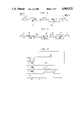
- FIG. 7 illustrates an exemplary pulse sequence in accordance with the invention for acquiring the FID signals used for measuring the gradient field attenuation due to eddy currents
- FIG. 8 illustrates a frequency domain representation of the FID signals acquired using the pulse sequence of FIG. 7;
- FIG. 9 illustrates a model of a superconducting magnet consisting of a gradient coil having n radiation shields
- FIG. 10 illustrates an exemplary embodiment of a pre-emphasis filter
- FIGS. 11, 12 and 13 illustrate a frequency domain representation of the FID signals acquired after successive compensations of a multi-exponentially decaying eddy current.
- FIG. 1a illustrates a cross-section view of a superconducting magnet assembly 2 and a block diagram of an associated electronic system 4 for operating magnet 2 and developing an analysis (pictoral or spectral) of a test object (not shown) placed therein.
- FIG. 1b illustrates a perspective view of magnet 2 with a cut-out to show its superconducting magnetic field windings.
- Superconducting magnet 2 includes a cylindrical housing 6 and end plates 8 having a hole in the center thereof for allowing the test object to be placed in a cylindrical bore 10 of magnet 2.
- a cylindrical vessel 12 within housing 6 includes a base (main) magnetic field winding 14 for developing a base magnetic field H o which is axially aligned within bore 10.
- vessel 12 typically includes a metallic chamber containing liquid nitrogen, which surrounds an additional metallic chamber containing liquid helium. Furthermore, at least one set of radiation shields is typically included within chamber 12 for providing insulation between the liquified gases and reduction of their evaporation rate due to thermal radiation.
- a gradient coil former 16 serves as a mounting for gradient coil assembly 18 having X, Y and Z gradient coils and a radio frequency (RF) coil 20.
- the gradient coil assembly with RF coil is then positioned inside bore 10 of magnet 2.
- Electronic system 4 includes a primary power supply 22 for supplying current (at least initially) to primary winding 14, a gradient/shim power supply 24 for supplying currents to gradient winding assembly 18 (and shim coils, not shown) and a transmit and receive (T/R) module 26 which transmits RF energy to RF coil 20 and receives magnetic resonance signals picked up by coil 20 which result from the precessing of the protons in the test object.
- a host computer 28 controls the application of gradient signals to gradient coil assembly 18 and, via its connection to T/R module 26, controls the processing of transmission and reception signals to and from RF coil 20.
- T/R module 26 and host computer 28 processes the received signals in a well known manner using one or two-dimensional Fourier transformation techniques for developing an image signal (or a spectral analysis) of the test object which is then used to display and/or record the information via display/record unit 30.
- the above-described apparatus is constructed and operates as a conventional MR device of the type well known to those skilled in the art and commercially available from a variety of manufacturers.
- gradient coils 18 generate substantially constant magnetic field gradients G x , G y and G z in the same direction as the main magnetic field, wherein the gradients are directed in mutually orthogonal X-, Y-, and Z- axis directions of a Cartesian coordinate system.
- the point (0,0,0) is referred to as the "isocenter" and is that point in space where none of the gradients have any effect.
- the isocenter is normally situated substantially at the center of the static magnetic field volume.
- the gradient magnetic fields are utilized in combination with RF pulses supplied from T/R module 26 to encode spatial information into the MR signals emminating from the region of the test object being studied.
- RF coil 20 selectively excites certain protons within the test object, and thereafter receives MR signals from the excited protons as they return (precess) to an equilibrium position established by the base main and gradient magnetic fields.
- the composite magnetic field (main field plus gradient field) affecting the test object is perturbed by magnetic field effects from eddy currents induced in one or more of the conducting media surrounding the gradient coils, such as the metallic walls of the closest radiation shields of chamber 12 (commonly referred to as cold or radiation shields).
- the eddy currents induced into one or more of the cold shields by the pulses applied to the gradient coils each produce their own magnetic field which opposes the desired applied gradient field and which decay with a time constant which is characteristic of that particular cold shield.
- the perturbation caused by the eddy currents distorts the phase and amplitude of the MR signals, thereby reducing the image quality/spectroscopic analysis accuracy in imagers/spectrometers, respectively.
- the eddy currents are substantially confined to a single conducting media. If there are several conducting media, one of them must be made dominant, typically the one closest to the gradient coil. This can be achieved by designed the first conductive cylinder (radiation shield) inside the magnet to be of very low resistance. Complete confinement can be achieved if the wall thickness of the cylinder is much larger than the skin depth of the lowest frequency component of a particular gradient switching sequence.
- a gradient amplifier 40 (included in gradient/shim power supply 24 shown in FIG. 1) for energizing gradient coil 18X to produce the G x gradient.
- a rectangular current pulse 42 applied to amplifier 40 would be amplified, as indicated by wave shape 44, and when used to energize the gradient coil, would result in a substantially rectangular gradient magnetic field pulse 46 being produced.
- the resulting magnetic field gradient has a finite rise and fall time as indicated at 48 and 50, respectively.
- such gradient distortions can lead to loss of signal and unintended phase dispersions of the nuclear spin vectors.
- the gradient distortions are reduced by application of a current pulse 42, as shown in FIG. 3, to a pre-emphasis filter which has amplitude and time constant coefficients set in accordance with the invention to pre-distort the current pulse, as indicated by waveshape 54.
- the amplified current pulse 56 is then applied to the gradient coil to produce the desired rectangular gradient pulse 46. Since in typical MR applications, gradient pulses are applied in at least each of the axes of the Cartesian coordinate system, an MR system for practicing the invention would normally have means functionally similar to that shown in FIG. 3 to achieve correction along all three axes. However, for simplicity, the following discussion will refer to correction along only one of the axes and would be repeated, if correction along other axes were required.
- FIG. 4 illustrates the flow chart of the invention.
- the flow chart will be briefly described and then followed with a more detailed description.
- step 60 the electrical isocenter of the gradient coil is found.
- step 62 an MR active sample is displaced a distance X from the isocenter, which distance is still within the linear range of the gradient coil and which allows an MR signal of significant amplitude to be developed, e.g., 4 cm.
- step 64 the local gradient field strength is determined in order that it can be used in a later step for calculating the correction coefficients for compensating the eddy currents.
- step 66 the gradient field attenuation due to eddy currents is determined by recording and analyzing the frequency shift characteristics of the FID MR signals obtained in the presence of the uncompensated gradient field.
- step 68 the frequency shift data gathered from step 66 is used for calculating the coupling and time constant coefficients needed for compensating the effects of the eddy currents. If one of the radiation shields has not been made fully dominant, multi-exponentially decaying eddy currents will exist and the eddy current effect having the longest time constant is characterized in this step.
- step 70 the coefficients calculated in step 68 are translated into compensation circuit values for pre-emphasis filter 52.
- step 72 if it is known that there is only one radiation shield causing the eddy current effect, this would be the end of the compensation procedure (for the x-axis). If however, the eddy current effect is multi-exponential, steps 66 through 70 are repeated, once for each of slowest decaying (longest time constant) eddy current effect remaining after the prior compensation.
- the coupling and time constant coefficients can be utilized in other filter implementations, such as an active filter, or may be utilized by the computer system of the MR device in order to initially generate current pulse 42 in order that it has the proper predistortion.
- step 60 although an inductive pick-up coil can be used to sense the magnetic field gradients inside gradient coil assembly 18, for simplicity, it is preferable to use only the components which are standard in MR devices for accomplishing the present invention. Therefore, for finding the isocenter of the gradient coil, a small sample composed of an MR active substance, conveniently a small bottle containing approximately 1 cc of water, is placed at a position (x,y,z) in gradient coil assembly 18, which position is intended to be a best estimate of the isocenter (0,0,0). As shown by waveforms 80-86 of FIG. 5, a magnetic field. gradient pulse 80 of long duration is applied, followed by a time delay T d .
- T d time delay
- a short 90° RF pulse 82 is then applied.
- the resulting free induction decay (FID) signal 84 is sampled, digitized, Fourier transformed and analyzed.
- the MR sample can be placed at any position along the coordinate axis under investigation except the origin of the gradient field.
- a typical displacement which offers both high signal sensitivity and is well within the linear range of a typical gradient coil is 4 cm.
- FIG. 6 illustrates positioning of an MR active sample 90 a distance "x" from the isocenter of gradient coil 18. Sample 90 will serve as the source of the MR signals used to study the gradient distortion caused by eddy currents.
- the measurement of local gradient strength is a pre-requisite for the calculation of the coupling constants between the gradient coil and the radiation shield.
- the angular resonant frequency ⁇ x of the FID signal is determined in accordance with equation 2. Since ⁇ B o is the angular resonant frequency in the absence of a gradient field, the frequency shift ⁇ g due to the local gradient can be calculated as
- ⁇ B o is measured as ⁇ g in the absence of a gradient field
- ⁇ x is determined as noted above and equation 3 is then solved for ⁇ g .
- FIG. 7 illustrates the pulse sequence employed for the measurement of the gradient field attenuation due to eddy currents (corresponding to step 66 of FIG. 4).
- a gradient pulse 92 of long duration t g typically 1000 ms is applied, followed by a time delay t d and a short, non-selective selective 90° RF pulse 94 having a duration typically of 10 ⁇ s.
- the free induction decay signal 96 which is frequency modulated by the decaying eddy currents (their effect upon the gradient pulse indicated by dashed lines 98), is then acquired during the A/D acquisition interval 100.
- the above procedure is repeated, with a plurality (n) of long duration gradient pulses followed by RF pulses having variable t d delays between the end of the gradient pulse and the application of the 90° RF pulse.
- the acquired plurality of FID signals are then Fourier transformed into the frequency domain, as illustrated in FIG. 8.
- the horizontal axis represents the frequency shift of the FID signals (i.e., normalized with respect to the local gradient strength ⁇ g ). Analysis of the shifting of the peak frequencies of the Fourier transformed FID signals yields the desired measurement of the eddy currents as a function of time delay t d .
- an MR device comprising a superconductive magnet with a set of radiation shields concentric with respect to the gradient coil is modeled as a system of mutually coupled lumped inductors and resistors.
- FIG. 9 depicts the magnetic equivalent model of such an MR device having n radiation shields, which model is used for calculation of the time constant and coupling correction coefficients, wherein each shield is modeled as a loop circuit having a resistor (R), inductor (L), mutual coupling coefficient (M) and current (i), with the gradient coil being driven by a constant current source.
- the generalized model of FIG. 9 is greatly simplified, and therefore made practically useful, by only considering one radiation shield at a time.
- the inventor has found that due to the structural nature of MR devices, although there can be several exponential decays related to the eddy currents, each decaying with a different time constant, a simplification is possible where only one time constant, the longest, is considered at a time.
- equation 4 is transformed into the s-domain:
- the magnet can be considered a linear device where the magnetic flux ( ⁇ ) is proportional to the current (i), we can write in the s-domain
- the amplitude correction coefficient is equal to M12/(1-M12) and the time constant correction coefficient is equal to T2(1-M12).
- the values for M12 and T2 can be extracted from the measurement of the uncompensated eddy currents by referring to the effect of the eddy currents upon the FID signals, shown in FIG. 8, using an exponential fit, wherein: ##EQU3## where ⁇ e(n) is the frequency shift due to eddy currents at the time delay td of index n (n varying from 1 to 15) and g is the frequency shift due to the local gradient (previously calculated).
- the proper correction coefficients i.e., time constant (TC) and amplitude (AMP), are calculated by applying equations 13 and 14 to the measurement data of FIG. 8.
- TC time constant
- AMP amplitude
- ⁇ g was 18,733 Hz.
- FIG. 10 An exemplary embodiment of a pre-emphasis filter is illustrated in circuit schematic form in FIG. 10.
- the filter includes an operational amplifier 110 and filter networks 112, 114 and 116. Although not shown, isolation amplifiers would also be included to isolate networks 112-116 from each other.
- the pre-distorted output is applied to the gradient amplifier (e.g., 40 of FIG. 3) for energizing the gradient coil.
- operational amplifier 110 is energized by a current pulse 42 through an input resistor R o and one or more parallel-connected RC networks 112-116.
- the number of RC networks depends upon the success of the MR device designer making only one of the radiation shields dominant. Dashed lines 118a and 118b suggest that additional RC networks may be added as needed.
- Each RC network is comprised at its input of a capacitor (e.g., C1) connected in series with an output variable resistor (e.g., R1). The common point between the capacitor and variable resistor is coupled to ground through a second variable resistor (e.g., R2).
- the circuit shown in FIG. 10 provides three exponential corrections since there are three RC networks. Preferably, only one RC network would be required.
- C1, R1 and R2 are adjusted in any of several well known manners to provide a TC of -0.343 seconds and an AMP of 1%.
- the inventor adjusted the RC network, using an oscilloscope, until the output pulse had a leading edge which had a 1% over shoot (i.e., 101% of its uncompensated amplitude) and a decay time constant of -0.343 seconds. This completes the compensation for the longest decaying component of the eddy current magnetic field.
- FIG. 12 indicating the Fourier transformed FID signals and TABLE III indicating the calculated TC and AMP values.
- FIG. 13 and TABLE IV show that the gradient pulse has now been substantially compensated for with respect to the decaying eddy currents, since the Fourier transformed FID signals no longer show any discernable frequency shift as a function of time delay t d .
Abstract
Description
ωx(t)=γ(B.sub.o +G.sub.x x) [2]
Φ.sub.g =γG.sub.x x=w.sub.x -γB.sub.o [3]
-M12 dil/dt+R2 i2+L2 di2/dt=0 [4]
-M12 s Il(s)+R2 I2 (s)+L2 s I2 (s)=0 [5]
I2 (s)=(M12 s Il(s))/(R2+L2 s) [6]
Φ2(s)=(M12 s Φ1 (s))/(R2+L2 s) [7]
Φt(s)=Φ1 (s) {1-(M12 s)/(R2+L2 s)} [8]
H(s)=1-(M12 s )/(s+1/T2) [9]
Φt(s)=H(s) Φ1(s)=1/s [10]
L.sup.-1 (Φ1 (s))={M12/(1-M12)} e.sup.-t/T2(1-M12) [12]
TABLE I ______________________________________ INDEX DELAY FREQ TC AMP ______________________________________ 15 5.000 0 0 14 3.000 2XXX XXX 13 1.000 12 -1.243 27 12 0.700 29 -0.343 226 11 0.500 59 -0.289 332 10 0.300 125 -0.265 386 9 0.100 305 -0.223 478 8 0.070 359 -0.185 524 7 0.050 403 -0.173 538 6 0.030 459 -0.153 558 5 0.010 550 -0.111 601 4 0.007 562 -0.136 591 3 0.005 576 -0.078 615 2 0.003 596 -0.060 627 1 0.001 611 -0.082 618 ______________________________________
TABLE II ______________________________________ INDEX DELAY FREQ TC AMP ______________________________________ 15 5.000 0 0 14 3.000 0XXX XXX 13 1.000 -5XXX XXX 12 0.700 -5XXX XXX 11 0.500 -2XXX XXX 10 0.300 27XXX XXX 9 0.100 137 -0.123 309 8 0.070 178 -0.113 331 7 0.050 215 -0.107 343 6 0.030 264 -0.098 359 5 0.010 332 -0.087 373 4 0.007 349 -0.060 393 3 0.005 362 -0.058 394 2 0.003 376 -0.050 399 1 0.001 391 -0.052 398 ______________________________________
TABLE III ______________________________________ INDEX DELAY FREQ TC AMP ______________________________________ 15 5.000 0 0 14 3.000 0XXX XXX 13 1.000 -5XXX XXX 12 0.700 -7XXX XXX 11 0.500 -5XXX XXX 10 0.300 2XXX XXX 9 0.100 15 -0.112 36 8 0.070 15XXX XXX 7 0.050 15XXX XXX 6 0.030 17 -0.130 22 5 0.010 34 -0.029 48 4 0.007 42 -0.016 65 3 0.005 46 -0.018 61 2 0.003 56 -0.011 75 1 0.001 66 -0.013 71 ______________________________________
              TABLE IV
______________________________________
INDEX     DELAY    FREQ       TC     AMP
______________________________________
15        5.000    0.000
14        3.000    -2.443     X.XXX  XX.X
13        1.000    -4.885     X.XXX  XX.X
12        0.700    -4.885     X.XXX  XX.X
11        0.500    -2.443     X.XXX  XX.X
10        0.300    2.443      X.XXX  XX.X
9         0.100    9.770      -0.144 19.5
8         0.070    9.770      X.XXX  XX.X
7         0.050    12.213     -0.090 21.3
6         0.030    9.770      0.090  7.0
5         0.010    4.885      0.029  3.5
4         0.007    4.885      X.XXX  XX.X
3         0.005    2.443      0.003  0.4
2         0.003    2.443      X.XXX  XX.X
1         0.001    2.443      X.XXX  XX.X
______________________________________
Claims (13)
Priority Applications (4)
| Application Number | Priority Date | Filing Date | Title |
|---|---|---|---|
| US07/392,872 US4965521A (en) | 1989-08-11 | 1989-08-11 | Method and apparatus for compensating eddy current effects in a magnetic resonance device having pulsed magnetic field gradients |
| CA002021877A CA2021877A1 (en) | 1989-08-11 | 1990-07-24 | Method and apparatus for compensating eddy current effects in a magnetic resonance device having pulsed magnetic field gradients |
| JP2213565A JP2793893B2 (en) | 1989-08-11 | 1990-08-10 | Method and apparatus for compensating eddy current magnetic field of magnetic resonance scanning apparatus |
| EP19900114607 EP0412394A3 (en) | 1989-08-11 | 1990-08-13 | Method and apparatus for compensating eddy current effects in a magnetic resonance device having pulsed magnetic field gradients |
Applications Claiming Priority (1)
| Application Number | Priority Date | Filing Date | Title |
|---|---|---|---|
| US07/392,872 US4965521A (en) | 1989-08-11 | 1989-08-11 | Method and apparatus for compensating eddy current effects in a magnetic resonance device having pulsed magnetic field gradients |
Publications (1)
| Publication Number | Publication Date |
|---|---|
| US4965521A true US4965521A (en) | 1990-10-23 |
Family
ID=23552360
Family Applications (1)
| Application Number | Title | Priority Date | Filing Date |
|---|---|---|---|
| US07/392,872 Expired - Lifetime US4965521A (en) | 1989-08-11 | 1989-08-11 | Method and apparatus for compensating eddy current effects in a magnetic resonance device having pulsed magnetic field gradients |
Country Status (4)
| Country | Link |
|---|---|
| US (1) | US4965521A (en) |
| EP (1) | EP0412394A3 (en) |
| JP (1) | JP2793893B2 (en) |
| CA (1) | CA2021877A1 (en) |
Cited By (22)
| Publication number | Priority date | Publication date | Assignee | Title |
|---|---|---|---|---|
| US5015955A (en) * | 1988-12-23 | 1991-05-14 | Picker International, Ltd. | Magnetic resonance methods |
| US5111147A (en) * | 1987-09-28 | 1992-05-05 | Centre National De La Recherche Scientifique | Gradient coil system for nmr machines |
| US5150055A (en) * | 1989-12-01 | 1992-09-22 | Hitachi, Ltd. | Nuclear magnetic resonance exciting device |
| WO1994001785A1 (en) * | 1992-07-10 | 1994-01-20 | Doty Scientific, Inc. | Solenoidal, octopolar, transverse gradient coils |
| DE4325031C1 (en) * | 1993-07-26 | 1994-11-03 | Siemens Ag | Method for acquiring gradient-induced eddy-current magnetic fields in an NMR (nuclear spin resonance) device |
| US5381093A (en) * | 1991-12-09 | 1995-01-10 | Kabushiki Kaisha Toshiba | Magnetic resonance imaging apparatus |
| US5530356A (en) * | 1992-07-20 | 1996-06-25 | Kabushiki Kaisha Toshiba | Method and apparatus for generating magnetic fields for nuclear magnetic resonance imaging with cross-talk compensation |
| US5530355A (en) * | 1993-05-13 | 1996-06-25 | Doty Scientific, Inc. | Solenoidal, octopolar, transverse gradient coils |
| US5554929A (en) * | 1993-03-12 | 1996-09-10 | Doty Scientific, Inc. | Crescent gradient coils |
| US5798679A (en) * | 1995-06-07 | 1998-08-25 | Houston Advanced Research Center | Magnetic flux bending devices |
| US5864233A (en) * | 1997-02-22 | 1999-01-26 | General Electric Company | Method to reduce eddy current effects in diffusion-weighted echo planar imaging |
| US6211675B1 (en) * | 1998-11-12 | 2001-04-03 | General Electric Company | Automatic measurement of gradient field distortion |
| US6448773B1 (en) | 2000-02-24 | 2002-09-10 | Toshiba America Mri, Inc. | Method and system for measuring and compensating for eddy currents induced during NMR imaging operations |
| EP1445623A1 (en) * | 2003-02-06 | 2004-08-11 | GE Medical Systems Global Technology Company LLC | Eddy current correction method and magnetic resonance imaging apparatus |
| US20040183535A1 (en) * | 2003-02-03 | 2004-09-23 | Siemens Aktiengesellschaft | Magnetic resonance apparatus with compensation of fields arising due to eddy currents |
| US20060145699A1 (en) * | 2003-02-05 | 2006-07-06 | Ham Cornelis L G | Compensation of magnetic field disturbances due to vibrations in an mri system |
| US20110200243A1 (en) * | 2008-10-20 | 2011-08-18 | Hitachi Medical Corporation | Magnetic resonance imaging apparatus and method |
| US20140218031A1 (en) * | 2013-02-05 | 2014-08-07 | Samsung Electronics Co., Ltd. | Magnetic resonance imaging apparatus and control method thereof |
| CN104808162A (en) * | 2014-01-23 | 2015-07-29 | 西门子公司 | Optimization of a magnetic resonance sequence of a magnetic resonance apparatus |
| WO2017032132A1 (en) * | 2015-08-25 | 2017-03-02 | Shanghai United Imaging Healthcare Co., Ltd. | System and method for an eddy-current field compensation in magnetic resonance imaging |
| US10989778B1 (en) * | 2019-12-20 | 2021-04-27 | Bruker France Sas | Method for measuring NMR-data of a target sample in an NMR spectrometer and NMR spectrometer |
| US11016161B2 (en) * | 2018-06-25 | 2021-05-25 | Samsung Electronics Co., Ltd. | Method and an apparatus for reconstructing magnetic resonance image |
Families Citing this family (5)
| Publication number | Priority date | Publication date | Assignee | Title |
|---|---|---|---|---|
| DE69215310T2 (en) * | 1991-09-19 | 1997-06-19 | Toshiba Kawasaki Kk | Method and apparatus for magnetic resonance imaging with the possibility of compensating for gradient fields disturbed by eddy currents |
| JP4809972B2 (en) * | 2000-11-15 | 2011-11-09 | ジーイー・メディカル・システムズ・グローバル・テクノロジー・カンパニー・エルエルシー | Gradient magnetic field generation method and apparatus, recording medium, and magnetic resonance imaging apparatus |
| JP4895039B2 (en) * | 2007-06-08 | 2012-03-14 | 日本電気株式会社 | Inductor, wiring board, and semiconductor device |
| JP5285244B2 (en) * | 2007-07-13 | 2013-09-11 | 株式会社日立メディコ | Magnetic resonance imaging system |
| JP5214209B2 (en) * | 2007-10-17 | 2013-06-19 | 株式会社日立メディコ | Magnetic resonance imaging system |
Citations (10)
| Publication number | Priority date | Publication date | Assignee | Title |
|---|---|---|---|---|
| US3873909A (en) * | 1967-08-21 | 1975-03-25 | Varian Associates | Gyromagnetic apparatus employing computer means for correcting its operating parameters |
| US4585995A (en) * | 1984-04-19 | 1986-04-29 | Technicare Corporation | Nuclear magnetic resonance eddy field suppression apparatus |
| US4585992A (en) * | 1984-02-03 | 1986-04-29 | Philips Medical Systems, Inc. | NMR imaging methods |
| US4647858A (en) * | 1985-07-29 | 1987-03-03 | General Electric Company | Methods for overcoming transient magnetic field inhomogeneity in nuclear magnetic resonance imaging |
| US4698591A (en) * | 1986-01-03 | 1987-10-06 | General Electric Company | Method for magnetic field gradient eddy current compensation |
| US4703275A (en) * | 1985-07-25 | 1987-10-27 | Picker International, Inc. | Method and apparatus to compensate for eddy currents in magnetic resonance imaging |
| US4733189A (en) * | 1986-06-03 | 1988-03-22 | Massachusetts Institute Of Technology | Magnetic resonance imaging systems |
| US4808956A (en) * | 1984-12-14 | 1989-02-28 | Thomson-Cgr | Coreless solenoidal magnet |
| US4920316A (en) * | 1989-03-30 | 1990-04-24 | Siemens Medical Systems, Inc. | Method and apparatus for reducing base field shifts in a magnetic resonance device due to pulsed magnetic field gradients |
| US4933626A (en) * | 1989-08-31 | 1990-06-12 | Field Effects | Methods and apparatus for controlling power amplifiers driving highly inductive loads |
Family Cites Families (3)
| Publication number | Priority date | Publication date | Assignee | Title |
|---|---|---|---|---|
| US4591789A (en) * | 1983-12-23 | 1986-05-27 | General Electric Company | Method for correcting image distortion due to gradient nonuniformity |
| US4680547A (en) * | 1985-06-10 | 1987-07-14 | General Electric Company | Gradient field switch for improved magnetic resonance imaging/spectroscopy system |
| FR2628839B1 (en) * | 1988-03-18 | 1991-08-16 | Thomson Cgr | METHOD FOR MEASURING THE EFFECTS OF EDDY CURRENTS |
-
1989
- 1989-08-11 US US07/392,872 patent/US4965521A/en not_active Expired - Lifetime
-
1990
- 1990-07-24 CA CA002021877A patent/CA2021877A1/en not_active Abandoned
- 1990-08-10 JP JP2213565A patent/JP2793893B2/en not_active Expired - Fee Related
- 1990-08-13 EP EP19900114607 patent/EP0412394A3/en not_active Withdrawn
Patent Citations (10)
| Publication number | Priority date | Publication date | Assignee | Title |
|---|---|---|---|---|
| US3873909A (en) * | 1967-08-21 | 1975-03-25 | Varian Associates | Gyromagnetic apparatus employing computer means for correcting its operating parameters |
| US4585992A (en) * | 1984-02-03 | 1986-04-29 | Philips Medical Systems, Inc. | NMR imaging methods |
| US4585995A (en) * | 1984-04-19 | 1986-04-29 | Technicare Corporation | Nuclear magnetic resonance eddy field suppression apparatus |
| US4808956A (en) * | 1984-12-14 | 1989-02-28 | Thomson-Cgr | Coreless solenoidal magnet |
| US4703275A (en) * | 1985-07-25 | 1987-10-27 | Picker International, Inc. | Method and apparatus to compensate for eddy currents in magnetic resonance imaging |
| US4647858A (en) * | 1985-07-29 | 1987-03-03 | General Electric Company | Methods for overcoming transient magnetic field inhomogeneity in nuclear magnetic resonance imaging |
| US4698591A (en) * | 1986-01-03 | 1987-10-06 | General Electric Company | Method for magnetic field gradient eddy current compensation |
| US4733189A (en) * | 1986-06-03 | 1988-03-22 | Massachusetts Institute Of Technology | Magnetic resonance imaging systems |
| US4920316A (en) * | 1989-03-30 | 1990-04-24 | Siemens Medical Systems, Inc. | Method and apparatus for reducing base field shifts in a magnetic resonance device due to pulsed magnetic field gradients |
| US4933626A (en) * | 1989-08-31 | 1990-06-12 | Field Effects | Methods and apparatus for controlling power amplifiers driving highly inductive loads |
Cited By (33)
| Publication number | Priority date | Publication date | Assignee | Title |
|---|---|---|---|---|
| US5111147A (en) * | 1987-09-28 | 1992-05-05 | Centre National De La Recherche Scientifique | Gradient coil system for nmr machines |
| US5015955A (en) * | 1988-12-23 | 1991-05-14 | Picker International, Ltd. | Magnetic resonance methods |
| US5150055A (en) * | 1989-12-01 | 1992-09-22 | Hitachi, Ltd. | Nuclear magnetic resonance exciting device |
| US5381093A (en) * | 1991-12-09 | 1995-01-10 | Kabushiki Kaisha Toshiba | Magnetic resonance imaging apparatus |
| WO1994001785A1 (en) * | 1992-07-10 | 1994-01-20 | Doty Scientific, Inc. | Solenoidal, octopolar, transverse gradient coils |
| US5530356A (en) * | 1992-07-20 | 1996-06-25 | Kabushiki Kaisha Toshiba | Method and apparatus for generating magnetic fields for nuclear magnetic resonance imaging with cross-talk compensation |
| US5554929A (en) * | 1993-03-12 | 1996-09-10 | Doty Scientific, Inc. | Crescent gradient coils |
| US5886548A (en) * | 1993-03-12 | 1999-03-23 | Doty Scientific Inc. | Crescent gradient coils |
| US5530355A (en) * | 1993-05-13 | 1996-06-25 | Doty Scientific, Inc. | Solenoidal, octopolar, transverse gradient coils |
| DE4325031C1 (en) * | 1993-07-26 | 1994-11-03 | Siemens Ag | Method for acquiring gradient-induced eddy-current magnetic fields in an NMR (nuclear spin resonance) device |
| US5798679A (en) * | 1995-06-07 | 1998-08-25 | Houston Advanced Research Center | Magnetic flux bending devices |
| US5864233A (en) * | 1997-02-22 | 1999-01-26 | General Electric Company | Method to reduce eddy current effects in diffusion-weighted echo planar imaging |
| US6211675B1 (en) * | 1998-11-12 | 2001-04-03 | General Electric Company | Automatic measurement of gradient field distortion |
| US6448773B1 (en) | 2000-02-24 | 2002-09-10 | Toshiba America Mri, Inc. | Method and system for measuring and compensating for eddy currents induced during NMR imaging operations |
| US6844733B2 (en) * | 2003-02-03 | 2005-01-18 | Siemens Aktiengesellschaft | Magnetic resonance apparatus with compensation of fields arising due to eddy currents |
| US20040183535A1 (en) * | 2003-02-03 | 2004-09-23 | Siemens Aktiengesellschaft | Magnetic resonance apparatus with compensation of fields arising due to eddy currents |
| US20060145699A1 (en) * | 2003-02-05 | 2006-07-06 | Ham Cornelis L G | Compensation of magnetic field disturbances due to vibrations in an mri system |
| US7372265B2 (en) * | 2003-02-05 | 2008-05-13 | Koninklijke Philips Electronics N.V. | Compensation of magnetic field disturbances due to vibrations in an MRI system |
| EP1445623A1 (en) * | 2003-02-06 | 2004-08-11 | GE Medical Systems Global Technology Company LLC | Eddy current correction method and magnetic resonance imaging apparatus |
| US6903550B2 (en) | 2003-02-06 | 2005-06-07 | Ge Medical Systems Global Technology Company, Llc | Eddy current correction method and magnetic resonance imaging apparatus |
| CN100387189C (en) * | 2003-02-06 | 2008-05-14 | Ge医疗系统环球技术有限公司 | Eddy current corrention method and magnetic resonance imaging appts. |
| US20110200243A1 (en) * | 2008-10-20 | 2011-08-18 | Hitachi Medical Corporation | Magnetic resonance imaging apparatus and method |
| US9720066B2 (en) * | 2013-02-05 | 2017-08-01 | Samsung Electronics Co., Ltd. | Magnetic resonance imaging apparatus and control method thereof |
| US20140218031A1 (en) * | 2013-02-05 | 2014-08-07 | Samsung Electronics Co., Ltd. | Magnetic resonance imaging apparatus and control method thereof |
| CN104808162A (en) * | 2014-01-23 | 2015-07-29 | 西门子公司 | Optimization of a magnetic resonance sequence of a magnetic resonance apparatus |
| KR20150088210A (en) * | 2014-01-23 | 2015-07-31 | 지멘스 악티엔게젤샤프트 | Optimization of a magnetic resonance sequence of a magnetic resonance apparatus |
| KR101655312B1 (en) | 2014-01-23 | 2016-09-07 | 지멘스 악티엔게젤샤프트 | Optimization of a magnetic resonance sequence of a magnetic resonance apparatus |
| US10126396B2 (en) | 2014-01-23 | 2018-11-13 | Siemens Aktiengesellschaft | Optimization of a magnetic resonance sequence of a magnetic resonance apparatus |
| WO2017032132A1 (en) * | 2015-08-25 | 2017-03-02 | Shanghai United Imaging Healthcare Co., Ltd. | System and method for an eddy-current field compensation in magnetic resonance imaging |
| US10408908B2 (en) | 2015-08-25 | 2019-09-10 | Shanghai United Imaging Healthcare Co., Ltd. | System and method for an eddy-current field compensation in magnetic resonance imaging |
| US10761172B2 (en) | 2015-08-25 | 2020-09-01 | Shanghai United Imaging Healthcare Co., Ltd. | System and method for an eddy-current field compensation in magnetic resonance imaging |
| US11016161B2 (en) * | 2018-06-25 | 2021-05-25 | Samsung Electronics Co., Ltd. | Method and an apparatus for reconstructing magnetic resonance image |
| US10989778B1 (en) * | 2019-12-20 | 2021-04-27 | Bruker France Sas | Method for measuring NMR-data of a target sample in an NMR spectrometer and NMR spectrometer |
Also Published As
| Publication number | Publication date |
|---|---|
| JPH0388309A (en) | 1991-04-12 |
| JP2793893B2 (en) | 1998-09-03 |
| EP0412394A2 (en) | 1991-02-13 |
| CA2021877A1 (en) | 1991-02-12 |
| EP0412394A3 (en) | 1991-07-24 |
Similar Documents
| Publication | Publication Date | Title |
|---|---|---|
| US4965521A (en) | Method and apparatus for compensating eddy current effects in a magnetic resonance device having pulsed magnetic field gradients | |
| Jehenson et al. | Analytical method for the compensation of eddy-current effects induced by pulsed magnetic field gradients in NMR systems | |
| US4698591A (en) | Method for magnetic field gradient eddy current compensation | |
| KR100481740B1 (en) | A method for measuring and compensating for spatially and temporally varying magnetic fields induced by eddy currents | |
| Van Vaals et al. | Optimization of eddy-current compensation | |
| CA1304126C (en) | Gradient and polarizing field compensation | |
| Boesch et al. | Temporal and spatial analysis of fields generated by eddy currents in superconducting magnets: optimization of corrections and quantitative characterization of magnet/gradient systems | |
| US6242915B1 (en) | Field-frequency lock system for magnetic resonance system | |
| EP0389911B1 (en) | Method and apparatus for reducing base field shifts in a magnetic resonance device due to pulsed field gradients | |
| US4928063A (en) | Automatic eddy current correction | |
| JP3096983B2 (en) | Magnetic field measurement method | |
| US6043656A (en) | Method for compensating an MRI system for residual magnetization | |
| US6025715A (en) | Method for compensating an MRI system for time dependent gradient field distortion | |
| US5451877A (en) | Method for the compensation of eddy currents caused by gradients in a nuclear magnetic resonance apparatus | |
| EP1004892A1 (en) | Compensating an MRI system for residual magnetization | |
| US6377043B1 (en) | Magnetic resonance method | |
| JPH0351172B2 (en) | ||
| US5587658A (en) | Shimming method for NMR magnet using unshielded gradient systems | |
| US6850066B2 (en) | Systems and methods for gradient compensation in magnetic resonance imaging | |
| JPH0418856B2 (en) | ||
| JP2528864B2 (en) | Inspection equipment using nuclear magnetic resonance | |
| Xia et al. | Purpose-designed probes and their applications for dynamic NMR microscopy in an electromagnet | |
| EP0280930A2 (en) | Magnetic resonance imaging method and apparatus | |
| WO1996021866A1 (en) | Nmr analysis of polypropylene in real time |
Legal Events
| Date | Code | Title | Description |
|---|---|---|---|
| AS | Assignment |
Owner name: SIEMENS MEDICAL SYSTEMS, INC., NEW JERSEY Free format text: ASSIGNMENT OF ASSIGNORS INTEREST.;ASSIGNOR:EGLOFF, HEINZ;REEL/FRAME:005167/0369 Effective date: 19891010 |
|
| AS | Assignment |
Owner name: SPECTROSCOPY IMAGING SYSTEMS, A CORP. OF DE., DELA Free format text: ASSIGNMENT OF ASSIGNORS INTEREST.;ASSIGNOR:SIEMENS MEDICAL SYSTEMS, INC.;REEL/FRAME:005268/0410 Effective date: 19900314 |
|
| STCF | Information on status: patent grant |
Free format text: PATENTED CASE |
|
| FEPP | Fee payment procedure |
Free format text: PAYOR NUMBER ASSIGNED (ORIGINAL EVENT CODE: ASPN); ENTITY STATUS OF PATENT OWNER: LARGE ENTITY |
|
| REMI | Maintenance fee reminder mailed | ||
| FPAY | Fee payment |
Year of fee payment: 4 |
|
| SULP | Surcharge for late payment | ||
| FPAY | Fee payment |
Year of fee payment: 8 |
|
| AS | Assignment |
Owner name: VARIAN, INC., CALIFORNIA Free format text: ASSIGNMENT OF ASSIGNORS INTEREST;ASSIGNOR:VARIAN ASSOCIATES, INC;REEL/FRAME:009901/0890 Effective date: 19990406 |
|
| FPAY | Fee payment |
Year of fee payment: 12 |
|
| REMI | Maintenance fee reminder mailed |