US4976860A - Conjugated polymer-cation exchanger composite membrane - Google Patents
Conjugated polymer-cation exchanger composite membrane Download PDFInfo
- Publication number
- US4976860A US4976860A US07/228,314 US22831488A US4976860A US 4976860 A US4976860 A US 4976860A US 22831488 A US22831488 A US 22831488A US 4976860 A US4976860 A US 4976860A
- Authority
- US
- United States
- Prior art keywords
- membrane
- composite membrane
- cation
- conjugated polymer
- solution
- Prior art date
- Legal status (The legal status is an assumption and is not a legal conclusion. Google has not performed a legal analysis and makes no representation as to the accuracy of the status listed.)
- Expired - Fee Related
Links
- 239000012528 membrane Substances 0.000 title claims abstract description 99
- 239000002131 composite material Substances 0.000 title claims abstract description 51
- 150000001768 cations Chemical class 0.000 claims abstract description 24
- 229920000547 conjugated polymer Polymers 0.000 claims abstract description 16
- 239000003729 cation exchange resin Substances 0.000 claims description 30
- 239000002245 particle Substances 0.000 claims description 25
- 239000010457 zeolite Substances 0.000 claims description 20
- 229910021536 Zeolite Inorganic materials 0.000 claims description 18
- NWUYHJFMYQTDRP-UHFFFAOYSA-N 1,2-bis(ethenyl)benzene;1-ethenyl-2-ethylbenzene;styrene Chemical compound C=CC1=CC=CC=C1.CCC1=CC=CC=C1C=C.C=CC1=CC=CC=C1C=C NWUYHJFMYQTDRP-UHFFFAOYSA-N 0.000 claims description 13
- 238000005341 cation exchange Methods 0.000 claims description 13
- HNPSIPDUKPIQMN-UHFFFAOYSA-N dioxosilane;oxo(oxoalumanyloxy)alumane Chemical compound O=[Si]=O.O=[Al]O[Al]=O HNPSIPDUKPIQMN-UHFFFAOYSA-N 0.000 claims description 11
- -1 polypyridazine Polymers 0.000 claims description 10
- 239000000203 mixture Substances 0.000 claims description 9
- HSFWRNGVRCDJHI-UHFFFAOYSA-N alpha-acetylene Natural products C#C HSFWRNGVRCDJHI-UHFFFAOYSA-N 0.000 claims description 4
- 229920001197 polyacetylene Polymers 0.000 claims description 4
- 229920000128 polypyrrole Polymers 0.000 claims description 3
- 125000001140 1,4-phenylene group Chemical group [H]C1=C([H])C([*:2])=C([H])C([H])=C1[*:1] 0.000 claims description 2
- 229920003026 Acene Polymers 0.000 claims description 2
- 229920000553 poly(phenylenevinylene) Polymers 0.000 claims description 2
- 229920000767 polyaniline Polymers 0.000 claims description 2
- 229920000417 polynaphthalene Polymers 0.000 claims description 2
- 229920000123 polythiophene Polymers 0.000 claims description 2
- 239000000126 substance Substances 0.000 abstract description 7
- 239000000243 solution Substances 0.000 description 53
- 238000000034 method Methods 0.000 description 31
- DHMQDGOQFOQNFH-UHFFFAOYSA-N Glycine Chemical compound NCC(O)=O DHMQDGOQFOQNFH-UHFFFAOYSA-N 0.000 description 30
- 238000012360 testing method Methods 0.000 description 30
- 230000035699 permeability Effects 0.000 description 28
- 239000008151 electrolyte solution Substances 0.000 description 26
- XLYOFNOQVPJJNP-UHFFFAOYSA-N water Substances O XLYOFNOQVPJJNP-UHFFFAOYSA-N 0.000 description 26
- WEVYAHXRMPXWCK-UHFFFAOYSA-N Acetonitrile Chemical compound CC#N WEVYAHXRMPXWCK-UHFFFAOYSA-N 0.000 description 24
- WQZGKKKJIJFFOK-GASJEMHNSA-N Glucose Natural products OC[C@H]1OC(O)[C@H](O)[C@@H](O)[C@@H]1O WQZGKKKJIJFFOK-GASJEMHNSA-N 0.000 description 18
- 239000008103 glucose Substances 0.000 description 18
- 150000002500 ions Chemical class 0.000 description 18
- KAESVJOAVNADME-UHFFFAOYSA-N Pyrrole Chemical compound C=1C=CNC=1 KAESVJOAVNADME-UHFFFAOYSA-N 0.000 description 16
- 239000004471 Glycine Substances 0.000 description 15
- CSCPPACGZOOCGX-UHFFFAOYSA-N Acetone Chemical compound CC(C)=O CSCPPACGZOOCGX-UHFFFAOYSA-N 0.000 description 14
- 239000003792 electrolyte Substances 0.000 description 13
- 239000011347 resin Substances 0.000 description 13
- 229920005989 resin Polymers 0.000 description 13
- PXHVJJICTQNCMI-UHFFFAOYSA-N Nickel Chemical compound [Ni] PXHVJJICTQNCMI-UHFFFAOYSA-N 0.000 description 12
- WCUXLLCKKVVCTQ-UHFFFAOYSA-M Potassium chloride Chemical compound [Cl-].[K+] WCUXLLCKKVVCTQ-UHFFFAOYSA-M 0.000 description 12
- 239000002253 acid Substances 0.000 description 12
- 239000003115 supporting electrolyte Substances 0.000 description 10
- 239000007864 aqueous solution Substances 0.000 description 9
- 229920000642 polymer Polymers 0.000 description 9
- 229920001577 copolymer Polymers 0.000 description 8
- 238000006116 polymerization reaction Methods 0.000 description 8
- VEXZGXHMUGYJMC-UHFFFAOYSA-M Chloride anion Chemical compound [Cl-] VEXZGXHMUGYJMC-UHFFFAOYSA-M 0.000 description 7
- 238000005349 anion exchange Methods 0.000 description 7
- 239000011248 coating agent Substances 0.000 description 7
- 238000000576 coating method Methods 0.000 description 7
- 238000005342 ion exchange Methods 0.000 description 7
- 239000000178 monomer Substances 0.000 description 7
- QKFFSWPNFCXGIQ-UHFFFAOYSA-M 4-methylbenzenesulfonate;tetraethylazanium Chemical compound CC[N+](CC)(CC)CC.CC1=CC=C(S([O-])(=O)=O)C=C1 QKFFSWPNFCXGIQ-UHFFFAOYSA-M 0.000 description 6
- FKNQFGJONOIPTF-UHFFFAOYSA-N Sodium cation Chemical group [Na+] FKNQFGJONOIPTF-UHFFFAOYSA-N 0.000 description 6
- 150000001450 anions Chemical class 0.000 description 6
- 229910052759 nickel Inorganic materials 0.000 description 6
- 239000001103 potassium chloride Substances 0.000 description 6
- 235000011164 potassium chloride Nutrition 0.000 description 6
- 229910001415 sodium ion Inorganic materials 0.000 description 6
- 229910019142 PO4 Inorganic materials 0.000 description 5
- 239000004816 latex Substances 0.000 description 5
- 229920000126 latex Polymers 0.000 description 5
- 229920000915 polyvinyl chloride Polymers 0.000 description 5
- 239000004800 polyvinyl chloride Substances 0.000 description 5
- 239000011148 porous material Substances 0.000 description 5
- 238000000926 separation method Methods 0.000 description 5
- LFQSCWFLJHTTHZ-UHFFFAOYSA-N Ethanol Chemical compound CCO LFQSCWFLJHTTHZ-UHFFFAOYSA-N 0.000 description 4
- FAPWRFPIFSIZLT-UHFFFAOYSA-M Sodium chloride Chemical compound [Na+].[Cl-] FAPWRFPIFSIZLT-UHFFFAOYSA-M 0.000 description 4
- PPBRXRYQALVLMV-UHFFFAOYSA-N Styrene Chemical compound C=CC1=CC=CC=C1 PPBRXRYQALVLMV-UHFFFAOYSA-N 0.000 description 4
- 229940023913 cation exchange resins Drugs 0.000 description 4
- 229920002678 cellulose Polymers 0.000 description 4
- 238000006243 chemical reaction Methods 0.000 description 4
- 238000001816 cooling Methods 0.000 description 4
- 229910052751 metal Inorganic materials 0.000 description 4
- 239000002184 metal Substances 0.000 description 4
- 238000002156 mixing Methods 0.000 description 4
- 239000003921 oil Substances 0.000 description 4
- 230000001590 oxidative effect Effects 0.000 description 4
- 238000003756 stirring Methods 0.000 description 4
- WYURNTSHIVDZCO-UHFFFAOYSA-N Tetrahydrofuran Chemical compound C1CCOC1 WYURNTSHIVDZCO-UHFFFAOYSA-N 0.000 description 3
- GWEVSGVZZGPLCZ-UHFFFAOYSA-N Titan oxide Chemical compound O=[Ti]=O GWEVSGVZZGPLCZ-UHFFFAOYSA-N 0.000 description 3
- MCMNRKCIXSYSNV-UHFFFAOYSA-N Zirconium dioxide Chemical compound O=[Zr]=O MCMNRKCIXSYSNV-UHFFFAOYSA-N 0.000 description 3
- 150000001413 amino acids Chemical class 0.000 description 3
- 235000010980 cellulose Nutrition 0.000 description 3
- 229920001940 conductive polymer Polymers 0.000 description 3
- MYRTYDVEIRVNKP-UHFFFAOYSA-N divinylbenzene Substances C=CC1=CC=CC=C1C=C MYRTYDVEIRVNKP-UHFFFAOYSA-N 0.000 description 3
- 230000004907 flux Effects 0.000 description 3
- 239000012466 permeate Substances 0.000 description 3
- 238000002360 preparation method Methods 0.000 description 3
- QAOWNCQODCNURD-UHFFFAOYSA-N sulfuric acid Substances OS(O)(=O)=O QAOWNCQODCNURD-UHFFFAOYSA-N 0.000 description 3
- IJGRMHOSHXDMSA-UHFFFAOYSA-N Atomic nitrogen Chemical compound N#N IJGRMHOSHXDMSA-UHFFFAOYSA-N 0.000 description 2
- 229910003944 H3 PO4 Inorganic materials 0.000 description 2
- 229910004861 K2 HPO4 Inorganic materials 0.000 description 2
- VYPSYNLAJGMNEJ-UHFFFAOYSA-N Silicium dioxide Chemical compound O=[Si]=O VYPSYNLAJGMNEJ-UHFFFAOYSA-N 0.000 description 2
- UIIMBOGNXHQVGW-UHFFFAOYSA-M Sodium bicarbonate Chemical compound [Na+].OC([O-])=O UIIMBOGNXHQVGW-UHFFFAOYSA-M 0.000 description 2
- DBMJMQXJHONAFJ-UHFFFAOYSA-M Sodium laurylsulphate Chemical compound [Na+].CCCCCCCCCCCCOS([O-])(=O)=O DBMJMQXJHONAFJ-UHFFFAOYSA-M 0.000 description 2
- QCWXUUIWCKQGHC-UHFFFAOYSA-N Zirconium Chemical compound [Zr] QCWXUUIWCKQGHC-UHFFFAOYSA-N 0.000 description 2
- 230000001070 adhesive effect Effects 0.000 description 2
- PNEYBMLMFCGWSK-UHFFFAOYSA-N aluminium oxide Inorganic materials [O-2].[O-2].[O-2].[Al+3].[Al+3] PNEYBMLMFCGWSK-UHFFFAOYSA-N 0.000 description 2
- WQZGKKKJIJFFOK-VFUOTHLCSA-N beta-D-glucose Chemical compound OC[C@H]1O[C@@H](O)[C@H](O)[C@@H](O)[C@@H]1O WQZGKKKJIJFFOK-VFUOTHLCSA-N 0.000 description 2
- 229920001400 block copolymer Polymers 0.000 description 2
- 238000012661 block copolymerization Methods 0.000 description 2
- 238000005266 casting Methods 0.000 description 2
- 239000001913 cellulose Substances 0.000 description 2
- 239000004927 clay Substances 0.000 description 2
- 239000008199 coating composition Substances 0.000 description 2
- 239000004020 conductor Substances 0.000 description 2
- 230000007547 defect Effects 0.000 description 2
- 238000010612 desalination reaction Methods 0.000 description 2
- 238000010438 heat treatment Methods 0.000 description 2
- 239000003456 ion exchange resin Substances 0.000 description 2
- 229920003303 ion-exchange polymer Polymers 0.000 description 2
- MLFHJEHSLIIPHL-UHFFFAOYSA-N isoamyl acetate Chemical compound CC(C)CCOC(C)=O MLFHJEHSLIIPHL-UHFFFAOYSA-N 0.000 description 2
- 238000004519 manufacturing process Methods 0.000 description 2
- 239000002798 polar solvent Substances 0.000 description 2
- 239000005518 polymer electrolyte Substances 0.000 description 2
- 239000011780 sodium chloride Substances 0.000 description 2
- 229940083575 sodium dodecyl sulfate Drugs 0.000 description 2
- 235000019333 sodium laurylsulphate Nutrition 0.000 description 2
- 229920003048 styrene butadiene rubber Polymers 0.000 description 2
- 239000000758 substrate Substances 0.000 description 2
- 239000000725 suspension Substances 0.000 description 2
- BFKJFAAPBSQJPD-UHFFFAOYSA-N tetrafluoroethene Chemical group FC(F)=C(F)F BFKJFAAPBSQJPD-UHFFFAOYSA-N 0.000 description 2
- 238000012546 transfer Methods 0.000 description 2
- 229910052726 zirconium Inorganic materials 0.000 description 2
- DPEYHNFHDIXMNV-UHFFFAOYSA-N (9-amino-3-bicyclo[3.3.1]nonanyl)-(4-benzyl-5-methyl-1,4-diazepan-1-yl)methanone dihydrochloride Chemical compound Cl.Cl.CC1CCN(CCN1Cc1ccccc1)C(=O)C1CC2CCCC(C1)C2N DPEYHNFHDIXMNV-UHFFFAOYSA-N 0.000 description 1
- RRZIJNVZMJUGTK-UHFFFAOYSA-N 1,1,2-trifluoro-2-(1,2,2-trifluoroethenoxy)ethene Chemical compound FC(F)=C(F)OC(F)=C(F)F RRZIJNVZMJUGTK-UHFFFAOYSA-N 0.000 description 1
- NHJVRSWLHSJWIN-UHFFFAOYSA-N 2,4,6-trinitrobenzenesulfonic acid Chemical compound OS(=O)(=O)C1=C([N+]([O-])=O)C=C([N+]([O-])=O)C=C1[N+]([O-])=O NHJVRSWLHSJWIN-UHFFFAOYSA-N 0.000 description 1
- TUFKHKZLBZWCAW-UHFFFAOYSA-N 2-(1-ethenoxypropan-2-yloxy)ethanesulfonyl fluoride Chemical compound C=COCC(C)OCCS(F)(=O)=O TUFKHKZLBZWCAW-UHFFFAOYSA-N 0.000 description 1
- IWTYTFSSTWXZFU-UHFFFAOYSA-N 3-chloroprop-1-enylbenzene Chemical group ClCC=CC1=CC=CC=C1 IWTYTFSSTWXZFU-UHFFFAOYSA-N 0.000 description 1
- 239000004342 Benzoyl peroxide Substances 0.000 description 1
- OMPJBNCRMGITSC-UHFFFAOYSA-N Benzoylperoxide Chemical compound C=1C=CC=CC=1C(=O)OOC(=O)C1=CC=CC=C1 OMPJBNCRMGITSC-UHFFFAOYSA-N 0.000 description 1
- 229920002134 Carboxymethyl cellulose Polymers 0.000 description 1
- KRHYYFGTRYWZRS-UHFFFAOYSA-M Fluoride anion Chemical compound [F-] KRHYYFGTRYWZRS-UHFFFAOYSA-M 0.000 description 1
- YCKRFDGAMUMZLT-UHFFFAOYSA-N Fluorine atom Chemical compound [F] YCKRFDGAMUMZLT-UHFFFAOYSA-N 0.000 description 1
- DGAQECJNVWCQMB-PUAWFVPOSA-M Ilexoside XXIX Chemical compound C[C@@H]1CC[C@@]2(CC[C@@]3(C(=CC[C@H]4[C@]3(CC[C@@H]5[C@@]4(CC[C@@H](C5(C)C)OS(=O)(=O)[O-])C)C)[C@@H]2[C@]1(C)O)C)C(=O)O[C@H]6[C@@H]([C@H]([C@@H]([C@H](O6)CO)O)O)O.[Na+] DGAQECJNVWCQMB-PUAWFVPOSA-M 0.000 description 1
- CERQOIWHTDAKMF-UHFFFAOYSA-M Methacrylate Chemical compound CC(=C)C([O-])=O CERQOIWHTDAKMF-UHFFFAOYSA-M 0.000 description 1
- ZOKXTWBITQBERF-UHFFFAOYSA-N Molybdenum Chemical compound [Mo] ZOKXTWBITQBERF-UHFFFAOYSA-N 0.000 description 1
- 229920002292 Nylon 6 Polymers 0.000 description 1
- 240000007930 Oxalis acetosella Species 0.000 description 1
- 235000008098 Oxalis acetosella Nutrition 0.000 description 1
- ABLZXFCXXLZCGV-UHFFFAOYSA-N Phosphorous acid Chemical compound OP(O)=O ABLZXFCXXLZCGV-UHFFFAOYSA-N 0.000 description 1
- OAICVXFJPJFONN-UHFFFAOYSA-N Phosphorus Chemical compound [P] OAICVXFJPJFONN-UHFFFAOYSA-N 0.000 description 1
- 239000004695 Polyether sulfone Substances 0.000 description 1
- 239000004642 Polyimide Substances 0.000 description 1
- 239000004372 Polyvinyl alcohol Substances 0.000 description 1
- XUIMIQQOPSSXEZ-UHFFFAOYSA-N Silicon Chemical compound [Si] XUIMIQQOPSSXEZ-UHFFFAOYSA-N 0.000 description 1
- 229920002125 Sokalan® Polymers 0.000 description 1
- RAHZWNYVWXNFOC-UHFFFAOYSA-N Sulphur dioxide Chemical group O=S=O RAHZWNYVWXNFOC-UHFFFAOYSA-N 0.000 description 1
- ATJFFYVFTNAWJD-UHFFFAOYSA-N Tin Chemical compound [Sn] ATJFFYVFTNAWJD-UHFFFAOYSA-N 0.000 description 1
- RTAQQCXQSZGOHL-UHFFFAOYSA-N Titanium Chemical compound [Ti] RTAQQCXQSZGOHL-UHFFFAOYSA-N 0.000 description 1
- 238000002835 absorbance Methods 0.000 description 1
- 239000000853 adhesive Substances 0.000 description 1
- 229910052782 aluminium Inorganic materials 0.000 description 1
- XAGFODPZIPBFFR-UHFFFAOYSA-N aluminium Chemical compound [Al] XAGFODPZIPBFFR-UHFFFAOYSA-N 0.000 description 1
- JYIBXUUINYLWLR-UHFFFAOYSA-N aluminum;calcium;potassium;silicon;sodium;trihydrate Chemical compound O.O.O.[Na].[Al].[Si].[K].[Ca] JYIBXUUINYLWLR-UHFFFAOYSA-N 0.000 description 1
- 238000005576 amination reaction Methods 0.000 description 1
- 239000003011 anion exchange membrane Substances 0.000 description 1
- 150000001491 aromatic compounds Chemical class 0.000 description 1
- 238000003491 array Methods 0.000 description 1
- 235000019400 benzoyl peroxide Nutrition 0.000 description 1
- 230000015572 biosynthetic process Effects 0.000 description 1
- UNYSKUBLZGJSLV-UHFFFAOYSA-L calcium;1,3,5,2,4,6$l^{2}-trioxadisilaluminane 2,4-dioxide;dihydroxide;hexahydrate Chemical compound O.O.O.O.O.O.[OH-].[OH-].[Ca+2].O=[Si]1O[Al]O[Si](=O)O1.O=[Si]1O[Al]O[Si](=O)O1 UNYSKUBLZGJSLV-UHFFFAOYSA-L 0.000 description 1
- 229910052663 cancrinite Inorganic materials 0.000 description 1
- 125000003178 carboxy group Chemical group [H]OC(*)=O 0.000 description 1
- 239000001768 carboxy methyl cellulose Substances 0.000 description 1
- 235000010948 carboxy methyl cellulose Nutrition 0.000 description 1
- 239000008112 carboxymethyl-cellulose Substances 0.000 description 1
- 239000003054 catalyst Substances 0.000 description 1
- 239000000919 ceramic Substances 0.000 description 1
- 229910052676 chabazite Inorganic materials 0.000 description 1
- 229920001429 chelating resin Polymers 0.000 description 1
- XTEGARKTQYYJKE-UHFFFAOYSA-N chloric acid Chemical compound OCl(=O)=O XTEGARKTQYYJKE-UHFFFAOYSA-N 0.000 description 1
- 229940005991 chloric acid Drugs 0.000 description 1
- 239000002734 clay mineral Substances 0.000 description 1
- 229910001603 clinoptilolite Inorganic materials 0.000 description 1
- 239000000805 composite resin Substances 0.000 description 1
- 238000010276 construction Methods 0.000 description 1
- 238000010924 continuous production Methods 0.000 description 1
- 238000007796 conventional method Methods 0.000 description 1
- 238000005520 cutting process Methods 0.000 description 1
- 238000001514 detection method Methods 0.000 description 1
- 238000011161 development Methods 0.000 description 1
- 238000000502 dialysis Methods 0.000 description 1
- 229910003460 diamond Inorganic materials 0.000 description 1
- 239000010432 diamond Substances 0.000 description 1
- BABWHSBPEIVBBZ-UHFFFAOYSA-N diazete Chemical compound C1=CN=N1 BABWHSBPEIVBBZ-UHFFFAOYSA-N 0.000 description 1
- 229920000359 diblock copolymer Polymers 0.000 description 1
- 125000001664 diethylamino group Chemical group [H]C([H])([H])C([H])([H])N(*)C([H])([H])C([H])([H])[H] 0.000 description 1
- OJLGWNFZMTVNCX-UHFFFAOYSA-N dioxido(dioxo)tungsten;zirconium(4+) Chemical compound [Zr+4].[O-][W]([O-])(=O)=O.[O-][W]([O-])(=O)=O OJLGWNFZMTVNCX-UHFFFAOYSA-N 0.000 description 1
- 239000012153 distilled water Substances 0.000 description 1
- 238000001035 drying Methods 0.000 description 1
- 230000005611 electricity Effects 0.000 description 1
- 229910052675 erionite Inorganic materials 0.000 description 1
- 238000001704 evaporation Methods 0.000 description 1
- 239000012013 faujasite Substances 0.000 description 1
- 229910001657 ferrierite group Inorganic materials 0.000 description 1
- 238000011049 filling Methods 0.000 description 1
- 239000011737 fluorine Substances 0.000 description 1
- 229910052731 fluorine Inorganic materials 0.000 description 1
- UQSQSQZYBQSBJZ-UHFFFAOYSA-N fluorosulfonic acid Chemical compound OS(F)(=O)=O UQSQSQZYBQSBJZ-UHFFFAOYSA-N 0.000 description 1
- 239000011888 foil Substances 0.000 description 1
- QJAUKMLCDVOYNX-UHFFFAOYSA-N formaldehyde;2-hydroxybenzenesulfonic acid Chemical compound O=C.OC1=CC=CC=C1S(O)(=O)=O QJAUKMLCDVOYNX-UHFFFAOYSA-N 0.000 description 1
- 229910052732 germanium Inorganic materials 0.000 description 1
- GNPVGFCGXDBREM-UHFFFAOYSA-N germanium atom Chemical compound [Ge] GNPVGFCGXDBREM-UHFFFAOYSA-N 0.000 description 1
- 239000011521 glass Substances 0.000 description 1
- 229910052735 hafnium Inorganic materials 0.000 description 1
- VBJZVLUMGGDVMO-UHFFFAOYSA-N hafnium atom Chemical compound [Hf] VBJZVLUMGGDVMO-UHFFFAOYSA-N 0.000 description 1
- YPDKFMYSITXPDU-UHFFFAOYSA-B hafnium(4+) tetraphosphate Chemical compound [Hf+4].[Hf+4].[Hf+4].[O-]P([O-])([O-])=O.[O-]P([O-])([O-])=O.[O-]P([O-])([O-])=O.[O-]P([O-])([O-])=O YPDKFMYSITXPDU-UHFFFAOYSA-B 0.000 description 1
- 150000002391 heterocyclic compounds Chemical class 0.000 description 1
- 239000011964 heteropoly acid Substances 0.000 description 1
- 229910052677 heulandite Inorganic materials 0.000 description 1
- 230000007062 hydrolysis Effects 0.000 description 1
- 238000006460 hydrolysis reaction Methods 0.000 description 1
- 229940117955 isoamyl acetate Drugs 0.000 description 1
- 229920002521 macromolecule Polymers 0.000 description 1
- 239000000395 magnesium oxide Substances 0.000 description 1
- CPLXHLVBOLITMK-UHFFFAOYSA-N magnesium oxide Inorganic materials [Mg]=O CPLXHLVBOLITMK-UHFFFAOYSA-N 0.000 description 1
- 239000011159 matrix material Substances 0.000 description 1
- 150000002739 metals Chemical class 0.000 description 1
- 239000011259 mixed solution Substances 0.000 description 1
- MEFBJEMVZONFCJ-UHFFFAOYSA-N molybdate Chemical compound [O-][Mo]([O-])(=O)=O MEFBJEMVZONFCJ-UHFFFAOYSA-N 0.000 description 1
- 229910052750 molybdenum Inorganic materials 0.000 description 1
- 239000011733 molybdenum Substances 0.000 description 1
- 229910052680 mordenite Inorganic materials 0.000 description 1
- 229910052757 nitrogen Inorganic materials 0.000 description 1
- 239000011556 non-electrolytic solution Substances 0.000 description 1
- 230000005693 optoelectronics Effects 0.000 description 1
- 125000000962 organic group Chemical group 0.000 description 1
- 230000003647 oxidation Effects 0.000 description 1
- 238000007254 oxidation reaction Methods 0.000 description 1
- 238000005191 phase separation Methods 0.000 description 1
- NBIIXXVUZAFLBC-UHFFFAOYSA-K phosphate Chemical compound [O-]P([O-])([O-])=O NBIIXXVUZAFLBC-UHFFFAOYSA-K 0.000 description 1
- 239000010452 phosphate Substances 0.000 description 1
- ACVYVLVWPXVTIT-UHFFFAOYSA-N phosphinic acid Chemical compound O[PH2]=O ACVYVLVWPXVTIT-UHFFFAOYSA-N 0.000 description 1
- DHRLEVQXOMLTIM-UHFFFAOYSA-N phosphoric acid;trioxomolybdenum Chemical compound O=[Mo](=O)=O.O=[Mo](=O)=O.O=[Mo](=O)=O.O=[Mo](=O)=O.O=[Mo](=O)=O.O=[Mo](=O)=O.O=[Mo](=O)=O.O=[Mo](=O)=O.O=[Mo](=O)=O.O=[Mo](=O)=O.O=[Mo](=O)=O.O=[Mo](=O)=O.OP(O)(O)=O DHRLEVQXOMLTIM-UHFFFAOYSA-N 0.000 description 1
- 239000011574 phosphorus Substances 0.000 description 1
- 229910052698 phosphorus Inorganic materials 0.000 description 1
- 229920003229 poly(methyl methacrylate) Polymers 0.000 description 1
- 229920001467 poly(styrenesulfonates) Polymers 0.000 description 1
- 229920000172 poly(styrenesulfonic acid) Polymers 0.000 description 1
- 229920002492 poly(sulfone) Polymers 0.000 description 1
- 229920000058 polyacrylate Polymers 0.000 description 1
- 229920002239 polyacrylonitrile Polymers 0.000 description 1
- 229920006393 polyether sulfone Polymers 0.000 description 1
- 229920001721 polyimide Polymers 0.000 description 1
- 229920005597 polymer membrane Polymers 0.000 description 1
- 239000003505 polymerization initiator Substances 0.000 description 1
- 239000004926 polymethyl methacrylate Substances 0.000 description 1
- 150000007519 polyprotic acids Polymers 0.000 description 1
- 229920005990 polystyrene resin Polymers 0.000 description 1
- 229940005642 polystyrene sulfonic acid Drugs 0.000 description 1
- 229920003053 polystyrene-divinylbenzene Polymers 0.000 description 1
- 229920001343 polytetrafluoroethylene Polymers 0.000 description 1
- 239000004810 polytetrafluoroethylene Substances 0.000 description 1
- 229920002451 polyvinyl alcohol Polymers 0.000 description 1
- 229920002620 polyvinyl fluoride Polymers 0.000 description 1
- USHAGKDGDHPEEY-UHFFFAOYSA-L potassium persulfate Chemical compound [K+].[K+].[O-]S(=O)(=O)OOS([O-])(=O)=O USHAGKDGDHPEEY-UHFFFAOYSA-L 0.000 description 1
- 238000000746 purification Methods 0.000 description 1
- 239000011342 resin composition Substances 0.000 description 1
- 239000011369 resultant mixture Substances 0.000 description 1
- 230000000717 retained effect Effects 0.000 description 1
- 238000001223 reverse osmosis Methods 0.000 description 1
- 150000003839 salts Chemical class 0.000 description 1
- 239000004065 semiconductor Substances 0.000 description 1
- 229910052710 silicon Inorganic materials 0.000 description 1
- 239000010703 silicon Substances 0.000 description 1
- 239000000377 silicon dioxide Substances 0.000 description 1
- 229920002050 silicone resin Polymers 0.000 description 1
- YPNVIBVEFVRZPJ-UHFFFAOYSA-L silver sulfate Chemical compound [Ag+].[Ag+].[O-]S([O-])(=O)=O YPNVIBVEFVRZPJ-UHFFFAOYSA-L 0.000 description 1
- 229910000367 silver sulfate Inorganic materials 0.000 description 1
- 239000011734 sodium Substances 0.000 description 1
- 229910052708 sodium Inorganic materials 0.000 description 1
- 235000017557 sodium bicarbonate Nutrition 0.000 description 1
- 229910000030 sodium bicarbonate Inorganic materials 0.000 description 1
- 229910052678 stilbite Inorganic materials 0.000 description 1
- 229910052718 tin Inorganic materials 0.000 description 1
- QUBMWJKTLKIJNN-UHFFFAOYSA-B tin(4+);tetraphosphate Chemical compound [Sn+4].[Sn+4].[Sn+4].[O-]P([O-])([O-])=O.[O-]P([O-])([O-])=O.[O-]P([O-])([O-])=O.[O-]P([O-])([O-])=O QUBMWJKTLKIJNN-UHFFFAOYSA-B 0.000 description 1
- 239000010936 titanium Substances 0.000 description 1
- 229910052719 titanium Inorganic materials 0.000 description 1
- JUWGUJSXVOBPHP-UHFFFAOYSA-B titanium(4+);tetraphosphate Chemical compound [Ti+4].[Ti+4].[Ti+4].[O-]P([O-])([O-])=O.[O-]P([O-])([O-])=O.[O-]P([O-])([O-])=O.[O-]P([O-])([O-])=O JUWGUJSXVOBPHP-UHFFFAOYSA-B 0.000 description 1
- 238000011282 treatment Methods 0.000 description 1
- WFKWXMTUELFFGS-UHFFFAOYSA-N tungsten Chemical compound [W] WFKWXMTUELFFGS-UHFFFAOYSA-N 0.000 description 1
- 229910052721 tungsten Inorganic materials 0.000 description 1
- 239000010937 tungsten Substances 0.000 description 1
- 229910052720 vanadium Inorganic materials 0.000 description 1
- GPPXJZIENCGNKB-UHFFFAOYSA-N vanadium Chemical compound [V]#[V] GPPXJZIENCGNKB-UHFFFAOYSA-N 0.000 description 1
- NLVXSWCKKBEXTG-UHFFFAOYSA-N vinylsulfonic acid Chemical compound OS(=O)(=O)C=C NLVXSWCKKBEXTG-UHFFFAOYSA-N 0.000 description 1
- 229910000166 zirconium phosphate Inorganic materials 0.000 description 1
- LEHFSLREWWMLPU-UHFFFAOYSA-B zirconium(4+);tetraphosphate Chemical compound [Zr+4].[Zr+4].[Zr+4].[O-]P([O-])([O-])=O.[O-]P([O-])([O-])=O.[O-]P([O-])([O-])=O.[O-]P([O-])([O-])=O LEHFSLREWWMLPU-UHFFFAOYSA-B 0.000 description 1
Images

Classifications
-
- B—PERFORMING OPERATIONS; TRANSPORTING
- B01—PHYSICAL OR CHEMICAL PROCESSES OR APPARATUS IN GENERAL
- B01D—SEPARATION
- B01D69/00—Semi-permeable membranes for separation processes or apparatus characterised by their form, structure or properties; Manufacturing processes specially adapted therefor
- B01D69/14—Dynamic membranes
- B01D69/141—Heterogeneous membranes, e.g. containing dispersed material; Mixed matrix membranes
-
- C—CHEMISTRY; METALLURGY
- C08—ORGANIC MACROMOLECULAR COMPOUNDS; THEIR PREPARATION OR CHEMICAL WORKING-UP; COMPOSITIONS BASED THEREON
- C08J—WORKING-UP; GENERAL PROCESSES OF COMPOUNDING; AFTER-TREATMENT NOT COVERED BY SUBCLASSES C08B, C08C, C08F, C08G or C08H
- C08J5/00—Manufacture of articles or shaped materials containing macromolecular substances
- C08J5/20—Manufacture of shaped structures of ion-exchange resins
- C08J5/22—Films, membranes or diaphragms
- C08J5/2206—Films, membranes or diaphragms based on organic and/or inorganic macromolecular compounds
- C08J5/2275—Heterogeneous membranes
-
- C—CHEMISTRY; METALLURGY
- C08—ORGANIC MACROMOLECULAR COMPOUNDS; THEIR PREPARATION OR CHEMICAL WORKING-UP; COMPOSITIONS BASED THEREON
- C08J—WORKING-UP; GENERAL PROCESSES OF COMPOUNDING; AFTER-TREATMENT NOT COVERED BY SUBCLASSES C08B, C08C, C08F, C08G or C08H
- C08J2353/00—Characterised by the use of block copolymers containing at least one sequence of a polymer obtained by reactions only involving carbon-to-carbon unsaturated bonds; Derivatives of such polymers
- C08J2353/02—Characterised by the use of block copolymers containing at least one sequence of a polymer obtained by reactions only involving carbon-to-carbon unsaturated bonds; Derivatives of such polymers of vinyl aromatic monomers and conjugated dienes
Definitions
- the present invention relates to a conjugated polymer-cation exchanger composite member and a process for preparing the same. More particularly, it relates to a charge-mosaic membrane suitable for concentration of an electrolyte solution or for separation of electrolytes from mixed solutions of electrolytes and low-molecular-weight nonelectrolytes, and to a process for preparing the same.
- a charge-mosaic membrane is a membrane which consists of parallel arrays of anion-exchange and cation-exchange elements passing through the membrane.
- the membrane When the membrane is applied to the permeation of an electrolytic solution, circulating electric currents are passed between the anion-exchange and cation-exchange elements through which ions are passed.
- the electrolytes are rapidly transferred in comparison with the nonelectrolytes.
- the charge-mosaic membrane is applicable to a membrane of piezodialysis used for concentration of an electrolyte solution, although the concentration was difficult in a conventional membrane separation technique. It also is used as a dialysis membrane for separation of electrolytes from mixed aqueous solutions of electrolytes and nonelectrolytes, or for separation or purification of amphoteric electrolytes, such as amino acid.
- the charge-mosaic membrane was initially prepared by a method wherein cation exchangers were united to anion exchangers or by a method wherein a resin membrane was partially immersed in a reaction solution for introducing both type of ion exchange groups into it (see U.S. Pat. No. 2,987,472; F. de Korosy, Nature, 197,635 (1963)). It is also reported that a membrane prepared by embedding a cation resin and an anion resin in a silicone resin membrane exhibits transfer phenomenon characterized by a charge-mosaic membrane (see J. N. Weinstein et al., Desalination, 12, 1(1973)). However, these initially developed membrane has large domains and are insufficient in mechanical strength. They also are difficult to produce in industrial scale.
- a charge-mosaic membrane is prepared by a casting method (see J. Shorr et al., Desalination, 14, 11(1974)), a blending method (Japanese Laid-Open Specification No. 14389/1979), a pile method or a suspension method.
- the casting method is a method wherein two different resins are poured in a mold and the blending method employs phase separation phenomenon which occurs when more than two different polymers are blended.
- the pile method is carried out by alternately piling a cation exchange film and an anion exchange film and then cutting it perpendicular to a film surface.
- the suspension method is conducted by suspending particles having one ion exchange group in a polymer solution which can have the other ion exchange group to obtain a mosaic structure.
- These methods have defects in formation of ion complex or film strength and therefore it is desired to obtain a charge-mosaic membrane not having the defects.
- the ionotropic-gel membrane method is a method producing a charge mosaic membrane by forming an ionotropic-gel membrane having a columner pore of which gel portion was constituted with one ion exchange resin and then filling the pore with the other ion exchange resin.
- the latex-polymer electrolyte method is divided into two.
- One is a method wherein a mixture of a styrenebutadiene copolymer latex and polystyrene sulfonic acid is formed into a film which is then cross-linked and chloromethylized followed by amination.
- the other is a method wherein a mixture of a styrene-butadiene copolymer latex and a quaternary aminated chloromethylstyrene is formed into a film and then cross-linked and sulfonated.
- the block copolymerization method can miniaturize the size of ion exchange areas.
- the mosaic structure is obtained by utilizing microphase separation phenomenon when forming a film by evaporating a block copolymer solution.
- anion and cation exchange groups are selectively introduced into the copolymer by suitable reactions to form a charge mosaic membrane.
- a conductive polymer such as polypyrrole
- the polymer prepared by oxidative polymerization is partially oxidized prior to the monomer.
- the polymer catches a counter anion of the supporting electrolyte in the electrolyte solution and thus anode doping is simultaneously progressed with the polymerization.
- This polymerization system makes it possible to enhance the electroconductivity of the polymer (for example, A. F. Diaz et al., J. Chem. Soc., Chem.
- the present invention is to provide a conjugated polymer-cation exchanger composite membrane suitable for a charge-mosaic membrane which is easily prepared and has excellent mechanical or chemical strength and good properties for charge-mosaic membrane.
- the composite membrane of the present invention comprises a conjugated polymer and cation-exchangers dispersed therein.
- the present invention also provide two preparation methods of the above composite membrane.
- One is a process characterized by electrochemically oxidative-polymerizing a monomer for a conjugated polymer in a solution containing cation exchangers.
- the other is a process characterized by electrochemically oxidative-polymerizing a monomer for a conjugated polymer in a solution containing a supporting electrolyte by employing as anode an electrode on which cation exchangers are coated.
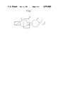
- FIG. 1 is a drawing schematically showing a sectional view of the conjugated polymer-cation exchange resin composite membrane.
- FIG. 2 is a drawing showing a container employed in Examples.
- the conjugated polymer employed in the present invention is a polymer having a conjugated construction in main chain.
- Non-limited examples of the conjugated polymers are polypyrrole, polythiophene, polyfurane, polyselenophene, polyaniline, polypyridazine, polyazophenylene, poly-p-phenylene, polynaphthalene, polyanthracene, polyacetylene, polyacene, poly-p-phenylenevinylene or a substituted one thereof, such as 3,4-C 1 -C 4 alkylpyrrole, 3,4-arylpyrrole, N-C 1 -C 4 alkylpyrrole, 3-C 1 -C 4 alkylthiophene.
- the conjugated polymer-cation exchanger composite membrane can be prepared as follow: (1) A monomer for the conjugated polymer is dissolved or dispersed in an electrolytic solution containing a suitable polar solvent and cation exchangers dispersed therein, and electrodes are then immersed therein to apply a voltage. After applying a certain amount of electricity, an anode is taken out of the solution and rinsed. The anode is then immersed in another electrolytic solution containing supporting electrolyte and the monomer for the above conjugated polymer and an electric potential is applied between the anode and a cathode to form a conjugated polymer-cation exchanger composite membrane on the anode.
- a monomer of the conjugated polymer and a supporting electrolyte are dissolved or dispersed in a suitable polar solvent to form an electrolytic solution. Electrodes are immersed in the electrolytic solution and an electric potential is applied, wherein an anode of the electrodes are coated with cation exchangers.
- the electrode employed in the above preparation is not limited, for example a conductive material, such as metal or semiconductor.
- the shape of the electrode also is not limited and can be a drum shape which makes possible continuous production (see Japanese Laid-Open Specification Nos. 228548/1985 or 72031/1986). Applied voltage can generally be from 0.2 to 30 V, preferably 0.2 to 10 V.
- the supporting electrolyte for electrolytic reaction can be conventional one known to the art.
- an exchange amount of the cation exchange area is equal to that of the anion exchange area.
- an exchange capacity of the cation exchanger incorporated into the membrane is calculated. Then, the integrated charge during electrolytic oxidative polymerization is controlled such that the anion exchange capacity is equal with the calculated cation exchange capacity, thus an amount of the conjugated polymer being controlled.
- the cation exchanger of the present invention include;
- strong acid cation exchange resins such as sulfonated polystyrene-divinylbenzene copolymer, phenolsulfonic acid-formaldehyde condensate, vinylsulfonic acid condensate, p-sulfonamidestyrene-styrene-di(p-vinylphenyl)sulfone copolymer and the like, some of which are available from Organo Company as Amberlite IR-120B, IR-122 and IR-124, from Dow Chemical Company as Dowex 50WX1, 50WX2, 50WX4, 50WX8, 50WX10, 50WX12 and 50WX16, from Diamond Shamrock Company as Duolite C-20, from Mitsubishi-Kasei Corp.
- Dia-ion SK1B, SK110 and SK112 from Muromachi Kagaku Kogyo-Kaisha-Ltd. as Muromac 50WX1, 50WX2, 50WX4, 50WX8, 50WX10, 50WX12, 50WX16 and the like;
- weak acid cation exchange resins such as methacrylic acid-divinylbenzene copolymer, maleic anhydridestyrene-divinylbenzene copolymer, phenolcarboxylic acidformaldehyde condensate, diallyphosphonic acid resins, phosphonic acid or phosphinic acid of styrene-divinylbenzene copolymer and the like, some of which are available as Amberlite IRC-50 and IRC-84, H70, Dia-ion WK10, WK11 and the like;
- fluorine-containing cation exchange resins such as perfluorosulfonic acid prepared by hydrolysis of a copolymer composed of tetrafluoroethylene and perfluoro(alkylvinylethyersulfonyl fluoride) (i.e. perfluoro(3,6-dioxa-4-methyl-7-octenesulfonyl fluoride)), and a copolymer of perfluorovinylether and tetrafluoroethylene to which at least one a sulfon group and a carboxyl group is added;
- perfluorosulfonic acid prepared by hydrolysis of a copolymer composed of tetrafluoroethylene and perfluoro(alkylvinylethyersulfonyl fluoride) (i.e. perfluoro(3,6-dioxa-4-methyl-7-octenesulfonyl fluoride)
- cation exchange celluloses such as diethylamino cellulose, sulfomethyl cellulose, carboxymethyl cellulose and the like;
- zeolites having cation exchange capacity such as faujasite, mordenite, offretite, cancrinite, heulandite, stilbite, chabazite, ferrierite, zeolite A, zeolite X ziolite Y, zeolite L, zeolite omega, erionite, ZSM-4, ZSM-5, clinoptilolite and the like;
- water-insoluble polybasic acids having cation exchange capacity for example phosphate, molydate, tangstate of tetravalent metal (titanium, zirconium, hafnium and tin), such as titanium phosphate, zirconium phosphate, hafnium phosphate, zirconium tungstate, zirconium molybdate, tin phosphate and the like;
- heteropolyacid made of phosphorus, germanium, silicon, molybdenum, tungsten, vanadium and the like, or a salt therefrom, for example 12-molybdophosphoric acid, 11-molybdo-1-vanadophosphoric acid, 10-molybdo-2-vanadophosphoric acid, 9-molybdo-3-vanadogermanic acid, 9-molybdo-3-vanadosilicic acid, 9-tangsto-3-vanadophosphoric acid, 6-molybdo-3-vabadisilicic acid, 6-tangsto-3-vanadogermanic acid and the like;
- hydrate oxides such as hydrate silica, hydrate titania, hydrate zirconia and the like, and composite oxides, such as silica-titania, titania-alumina, silica-alumina, silica-magnesia, alumina-zirconia and the like;
- acid clay minerals such as activated clay, Japanese acid clay and the like.
- Cation exchange capacity of the above mentioned ion exchangers is at least 0.1 meg/g, preferably at least 0.5 meg/g.
- preferred for the present invention are the cation exchange resins and the zeolites.
- the shape of the cation exchangers is not limited, but preferred size of the cation exchanger is within the range of 0.3 to 10 micrometer because thick film increases membrane permeation resistance.
- the cation exchanger having a size of the above range increases circulating electric currents in number per unit area to enhance the properties of the charge-mosaic membrane.
- the above cation exchangers are dispersed in an electrolytic solution or coated on an electrode.
- the number of the exchangers is at least 5 ⁇ 10 7 particles/ml in the electrolytic solution and at least 2 ⁇ 10 4 particles/cm 2 , preferably at least 4 ⁇ 10 4 particles/cm 2 for coating.
- a coating composition dispersing cation exchangers in a film-forming resin composition can be employed.
- the film-forming resins are polyvinyl chloride resins, polystyrene resins, acrylate polymer, methacrylate polymer and the like, but they are not limited to the above listed one. They include all film-forming resin capable of forming a uniform film when coated on the electrode.
- the concentration of the coating composition is 0.1 to 10% by weight, preferably 0.3 to 1% by weight.
- the porous support employed in the present invention can be one which has very small permeation resistance and has a function supporting the composite membrane of the present invention.
- the shape of the substrate also is not limited, such as panel, film, tube and the like.
- the porous substrates are glassy porous materials, sintered metals, ceramics, cellulose ester, polyethersulfone, polysulfone, polyimide, polytetrafluoroethylene, polyvinyl fluoride, nylon 6, polyacrylonitrile, polyvinyl chloride, polymethyl methacrylate and the conjugated polymer mentioned above.
- the process for uniting the composite membrane of the present invention with the porous support is as follow: (1) the conjugated polymer-cation exchanger composite membrane is floated on the surface of water and dipped up from water with the porous support membrane to attach it. (2) The composite membrane is pumped up on the porous support by a vacuum pump. (3) The composite membrane is pressed on the porous support. (4) The composite membrane is prepared and then continued to prepare under a condition making the membrane porous.
- the above process is not limited. If desired, the composite membrane may be attached on the porous support by using adhesives. The united composite membrane is further subjected to a heat treatment to enhance adhesive properties.
- FIG. 1 is a drawing schematically showing a sectional view of the conjugated polymer-cation exchange resin composite membrane.
- the cation exchanger 2 is dispersed in the conjugated polymer membrane 1.
- the conjugate polymer membrane 1 is acted as an anion exchange membrane and a circulating electric current generates between the cation exchange area and the anion exchange area as indicating 3 in FIG. 1.
- the current accelerates transport of the electrolyte.
- dispenser herein is meant that the cation exchangers 2 are mechanically and/or chemically retained with scattered in the conjugated polymer 1.
- cation exchange resin particles having a particle size of 2.6 micrometer and an exchange capacity of 3.1 meg/g was added in 200 ml of an acetonitrile solution containing 0.1M of pyrrole, in which a transparent electrode coated glass electrode (hereinafter referred to as "Nesaglass electrode") and a nickel cathode both having 6.0 cm ⁇ 7.0 cm were immersed.
- a voltage was applied between both electrodes sufficient to have a current density of 7.5 ⁇ A/cm 2 .
- the electrodes were taken out from the electrolytic solution and the anode was rinsed with ion exchanged water and ethanol.
- the electrodes then, were immersed in an acetonitrile solution containing 0.5M of pyrrole and 0.05M of tetraethylammonium-p-toluenesulfonate and a voltage was applied between both electrodes sufficient to have a current density of 0.3 mA/cm 2 .
- the electrodes were taken out from the electrolytic solution and the produced polypyrrole-cation exchange resin composite membrane was removed from the surface of the electrode to rinse with acetone and then dry under a reduced pressure at room temperature.
- the obtained polypyrrole-cation exchange resin composite membrane was immersed over night in an aqueous solution for a permeability test and subjected to the permeability test.
- the permeability test as shown in FIG. 2, was carried out by holding the composite membrane 4 between two 400 ml cells in a thermostat 5, one of which was filled with ion exchanged water and the other filled with three different solutions, i.e. an electrolytic solution, a nonelectrolytic solution and a mixture thereof.
- An area of the permeation membrane was 12.6 cm 2 and a test temperature was 25° C.
- the result is shown in Table 1.
- a concentration of sodium chloride was determined by electric conductivity using an apparatus available from TOA Electronics Ltd. as CM-20S and that of glucose was determined by using Glucose B-Test wako available from Wako Pure Chemical Industries, LTD.
- the cation exchange resin particles were prepared as follow:
- a one liter four neck flask was charged with 670 g of ion exchange water and 73 g of styrene and heated to 80° C. in an oil bath with stirring under nitrogen blanket. Then, 0.74 g of potassium persulfate as polymerization initiator was added and heating was continued with stirring, while the stirring rate was adjusted to 350 rpm. The polymerization reaction was terminated for 5 to 10 hours and the agglomerate was filtered away to obtain a latex. A particle size of the latex was determined by a submicron particle analyzer available from Colter Company as Model N4 and a scanning type electron microscope available from Nippon Electronics Company as JSM-35C to find an average particle size of 980 nm.
- zeolite available from Toyo Soda MFG Co. Ltd. as Zeoram A-3
- Zeoram A-3 One gram of zeolite (available from Toyo Soda MFG Co. Ltd. as Zeoram A-3) was added in 200 ml of acetonitrile solution containing 0.1M of pyrrole, in which a Nesaglass electrode and a nickel cathode both having 6.0 cm ⁇ 7.0 cm were immersed. A voltage was applied between both electrodes sufficient to have a current density of 7.5 ⁇ A/cm 2 . After passing 0.15 Coulomb, the electrodes were taken out from the electrolytic solution and the anode was rinsed with ion exchanged water and ethanol.
- the electrodes then, were immersed in an acetonitrile solution containing 0.5M of pyrrole and 0.05M of tetraethylammonium-p-toluenesulfonate and a voltage was applied between both electrodes sufficient to have a current density of 0.3 mA/cm 2 .
- the electrodes were taken out from the electrolytic solution and the produced polypyrrole-zeolite composite membrane was removed from the surface of the electrode to rinse with acetone and then dry under a reduced pressure at room temperature.
- the obtained polypyrrole-zeolite composite membrane was immersed over night in an aqueous solution for a permeability test and subjected to the permeability test, as generally described in Example 1. The result of the test is shown in Table 2.
- a supporting electrolyte i.e. tetraethylammonium-p-toluenesulfonate, was added in acetonitrile solution containing 0.1M of pyrrole to form a 0.05M electrolytic solution.
- Cation exchange resin particles prepared in Example 1 were coated on a Nesaglass electrode having 6.0 cm ⁇ 7.0 cm and was immersed in the obtained electrolytic solution as an anode, while a nickel plate having the same size was immersed as cathode.
- a voltage was applied between both electrodes sufficient to have a current density of 0.3 mA/cm 2 .
- the cation resin particles-coated Nesaglass electrode was prepared as follow: The cation exchange resin particles were added to a tetrahydrofurane solution containing 0.5% by weight of polyvinyl chloride to form a coating solution containing 10% by weight of the resin particles. Several drops of the coating solution were dropped onto a Nesaglass electrode and coated thereon by using YBA type baker applicator available from Yoshimitsu Seiki Company. The electrode was dried for more than one hour.
- a supporting electrolyte i.e. tetraethylammonium-p-toluenesulfonate, was added in an acetonitrile solution containing 0.5M of pyrrole to form a 0.05M electrolytic solution.
- the same zeolite as Example 2 was coated on a Nesaglass electrode having 6.0 cm ⁇ 7.0 cm and was immersed in the obtained electrolytic solution as anode, while a nickel plate having the same size as the Nesaglass electrode was immersed in it as cathode.
- a voltage was applied between both electrodes sufficient to have a current density of 0.3 mA/cm 2 .
- the electrodes were taken out from the electrolytic solution and the produced polypyrrole-zeolite composite membrane was removed from the surface of the electrode to rinse with acetone and then dry under a reduced pressure at room temperature.
- the obtained polypyrrole-zeolite composite membrane was immersed over night in an aqueous solution for a permeability test and subjected to the permeability test, as generally described in Example 1. The result of the test is shown in Table 4.
- the zeolite-coated Nesaglass electrode was prepared as follow: The zeolite was added to a tetrahydrofurane solution containing 0.5% by weight of polyvinyl chloride to form a coating solution containing 10% by weight of the zeolite. Several drops of the coating solution were dropped onto a Nesaglass electrode and coated thereon by using YBA type baker applicator available from Yoshimitsu Seiki Company. The Nesaglass electrode was dried for more one hour.
- Example 2 A polypyrrole-zeolite composite membrane prepared in Example 2 was floated on the surface of water and dipped out on a stainless mesh. The obtained composite membrane was subjected to the permeability test, as generally described in Example 1. The result is shown in Table 6.
- a supporting electrolyte i.e. tetraethylammonium-p-toluenesulfonate, was added in acetonitrile solution containing 0.2M of pyrrole to form a 0.1M electrolytic solution.
- Cation exchange resin particles (Muromac 50W-X8 of 400 mesh) were added to the electrolytic solution, in which a Nesaglass electrode having 3.5 cm ⁇ 5.0 cm and a nickel plate having the same size were immersed. A constant voltage of 3.6 V was applied between both electrodes.
- the electrodes were taken out from the electrolytic solution and the produced polypyrrole-cation exchange resin composite membrane was removed from the surface of the electrode to rinse with acetone and then dry under a reduced pressure at room temperature to obtain a composite membrane of 70 micrometer.
- the obtained polypyrrole-cation exchange resin composite membrane was immersed over night in an aqueous solution for a permeability test and subjected to the permeability test.
- the permeability test was carried out using a filter apparatus for reverse osmosis (available from ULVAC Service Corporation as RO-3).
- the area of permeation membrane was 4.9 cm 2 .
- the test membrane was placed on a metallic porous support and a 0.1 mM potassium chloride solution was contacted with the membrane under a pressure of 60 Kg/cm 2 to conduct a test.
- the membrane has a permeation flux of 0.36 cm/hr and a concentration degree of 60%.
- the concentration degree was calculated from the following equation; ##EQU1##
- a supporting electrolyte i.e. tetraethylammonium-p-toluenesulfonate, was added in and acetonitrile solution containing 0.2M of pyrrole to form a 0.1M electrolytic solution.
- Cation exchange resin particles (Muromac 50W-X8 of 400 mesh) were coated on a Nesaglass electrode having 3.5 cm ⁇ 5.0 cm. The cation exchange resin particle-coated Nesaglass electrode and a nickel plate having the same size were immersed. A constant voltage of 3.6 V was applied between both electrodes.
- the electrodes were taken out from the electrolytic solution and the produced polypyrrole-cation exchange resin composite membrane was removed from the surface of the electrode to rinse with acetone and then dry under a reduced pressure at room temperature to obtain a composite membrane of 70 micrometer.
- the obtained polypyrrole-cation exchange resin composite membrane was immersed over night in an aqueous solution for a permeability test and subjected to the permeability test, as generally described in Example 7.
- the membrane has a permeation flux of 0.16 cm/hr and a concentration degree of 80%.
- a 10 mM glucose solution was contacted with polypyrrole-cation exchange resin composite membrane prepared in Example 8 under a pressure of 60 Kg/cm 2 and a permeability test was carried out. Its permeation flux was 0.23 cm/hr and no glucose was detected in the permeated solution. The detection of glucose was conducted with Glucose B-Test Wako (Wako Pure Chemical Industries, Ltd.).
- a polypyrrole-cation exchange resin composite membrane prepared in Example 8 was held between a mixture of 10 mM of glucose and potassium chloride (I phase) and distilled water (II phase) and the concentration change of glucose and potassium chloride in I and II phase was measured with time. The result is shown in Table 7. The concentration of potassium chloride in I phase became lower with time, while that in II phase became higher with time. Even when the concentration of potassium chloride was equal in both I and II phase, no glucose was detected in II phase. This shows that electrolyte or low molecular weight nonelectrolyte can separate from a mixture containing both electrolyte and nonelectrolyte by using the polypyrrole-cation exchange resin composite membrane.
- glycine exists as cation at a pH of not more than 1.3, as Zwitter ion at a pH of 2.3 to 9.6 and as anion at a pH of not less than 9.6.
- the Zwitter ion type glycine superficially has no electric charge. Accordingly, depending on the pH value of the solution, glycine can be changed betwee electrolyte and nonelectrolyte. Table 4 shows that, when glycine was electrolyte, it permeated through the membrane and when it was not electrolyte it was not able to permeate through the membrane. This evidences that the conjugated polymer-cation exchanger composite resin should be a charge mosaic membrane.
- a pH of the solution was adjusted by mixing necessary amount of 100 mM H 3 PO 4 , KH 2 PO 4 , K 2 HPO 4 and K 3 PO 4 solutions.
- a pH of the glycine solution was adjusted by mixing necessary amounts of 100 mM H 3 PO 4 , KH 2 PO 4 , K 2 HPO 4 and K 3 PO 4 solutions containing 10 mM of glycine.
- Quantitative determination of glycine was carried out by using nitrophenylized glycine. It was prepared by adding 1 ml of 4% sodium hydrogencarbonate solution and 1 ml of 0.1% trinitrobenzenesulfonic acid solution to 1 ml of II phase solution which was left for a suitable period of time. The resultant mixture was shielded with aluminum foil and allowed to stand at 50° C. for 2 hours. After cooling, 0.5 ml of 1M chloric acid was added to the mixture to terminate the reaction and the absorbance of 345 nm was measured to find a concentration of glycine.
- a permeability test of amino acid was carried out by using a polypyrrole-zeolite composite membrane prepared in Example 2. The test was carried out as generally describen in Example 11. The result is shown in Table 9.
Abstract
Description
              TABLE 1
______________________________________
                          Permeability coeffi-
I Phase     II Phase      cient (cm/sec)
______________________________________
100 mM Sodium
            Ion exchanged 6.5 × 10.sup.-4
chloride solution
            water
100 mM Glucose
            Ion exchanged 0
solution    water
Mixture solution
            Ion exchanged NaCl 5.9 × 10.sup.-4
of 100 mM sodium
            water         Glucose 0
chloride and 100
mM glucose
______________________________________
              TABLE 2
______________________________________
                        Permeability coeffi-
I Phase     II Phase    cient (cm/sec)
______________________________________
100 mM Sodium
            Ion exchanged
                        1.9 × 10.sup.-4
chloride solution
            water
100 mM Glucose
            Ion exchanged
                        4.1 × 10.sup.-6
solution    water
______________________________________
              TABLE 3
______________________________________
                        Permeability coeffi-
I Phase     II Phase    cient (cm/sec)
______________________________________
100 mM Sodium
            Ion exchanged
                        5.5 × 10.sup.-4
chloride solution
            water
100 mM Glucose
            Ion exchanged
                        0
solution    water
______________________________________
              TABLE 4
______________________________________
                        Permeability coeffi-
I Phase     II Phase    cient (cm/sec)
______________________________________
100 mM Sodium
            Ion exchanged
                        1.5 × 10.sup.-4
chloride solution
            water
100 mM Glucose
            Ion exchanged
                        2.8 × 10.sup.-6
solution    water
______________________________________
              TABLE 5
______________________________________
                        Permeability coeffi-
I Phase     II Phase    cient (cm/sec)
______________________________________
100 mM Sodium
            Ion exchanged
                        5.1 × 10.sup.-4
chloride solution
            water
100 mM Glucose
            Ion exchanged
                        0
solution    water
______________________________________
              TABLE 6
______________________________________
                        Permeability coeffi-
I Phase     II Phase    cient (cm/sec)
______________________________________
100 mM Sodium
            Ion exchanged
                        1.8 × 10.sup.-4
chloride solution
            water
100 mM Glucose
            Ion exchanged
                        3.9 × 10.sup.-6
solution    water
______________________________________
              TABLE 7
______________________________________
Glucose concentration
                    Potassium chloride
(mM)                concentration (mM)
Time    I Phase II Phase    I Phase
                                  II Phase
______________________________________
 0      10      0           10    0
 4      10      0           8.7   1.3
 8      10      0           7.8   2.2
12      10      0           6.9   3.1
30      10      0           5     5
40      10      0           5     5
______________________________________
              TABLE 8
______________________________________
                   Permeability coeffici-
pH of I and II phase
                   ent of glycine
______________________________________
2                  1.33 × 10.sup.-4
3                  5.70 × 10.sup.-5
4                  0
6                  0
9                  1.07 × 10.sup.-4
11.5               9.19 × 10.sup.-5
______________________________________
              TABLE 9
______________________________________
               Permeability coeffici-
pH of I and II phase
               ent of glycine
______________________________________
2              8.6 × 10.sup.-5
6              7.7 × 10.sup.-5
10             1.2 × 10.sup.-4
______________________________________
Claims (5)
Applications Claiming Priority (2)
| Application Number | Priority Date | Filing Date | Title |
|---|---|---|---|
| JP62-195481 | 1987-08-04 | ||
| JP19548187 | 1987-08-04 |
Publications (1)
| Publication Number | Publication Date |
|---|---|
| US4976860A true US4976860A (en) | 1990-12-11 |
Family
ID=16341802
Family Applications (1)
| Application Number | Title | Priority Date | Filing Date |
|---|---|---|---|
| US07/228,314 Expired - Fee Related US4976860A (en) | 1987-08-04 | 1988-08-04 | Conjugated polymer-cation exchanger composite membrane |
Country Status (4)
| Country | Link |
|---|---|
| US (1) | US4976860A (en) |
| EP (1) | EP0302494B1 (en) |
| DE (1) | DE3875548T2 (en) |
| ES (1) | ES2052648T3 (en) |
Cited By (18)
| Publication number | Priority date | Publication date | Assignee | Title |
|---|---|---|---|---|
| US5096586A (en) * | 1990-08-28 | 1992-03-17 | Regents Of The University Of California | Membranes having selective permeability |
| US5422246A (en) * | 1990-12-14 | 1995-06-06 | Nederlandse Organisatie Voor Toegepast-Natuurwetenschappelijk Onderzoek Tno | Electrode having a polymer coating with a redox enzyme bound thereto, the polymer coating being formed on the walls of pores extending through a porous membrane |
| US5543045A (en) * | 1992-09-25 | 1996-08-06 | Dainichiseika Color & Chemicals Mfg. Co., Ltd. | Charge mosaic membrane and production process thereof |
| WO1997044121A1 (en) * | 1996-05-17 | 1997-11-27 | Colorado School Of Mines | Membrane separation of components in a fluid mixture |
| US6051967A (en) * | 1995-09-08 | 2000-04-18 | U.S. Philips Corporation | Electric field measurement system |
| US6156202A (en) * | 1998-05-15 | 2000-12-05 | Council Of Scientific And Industrial Research And Department Of Biotechnology | Conducting polymer membrane and a process for the preparation of the same membrane |
| US6663775B2 (en) * | 1998-02-25 | 2003-12-16 | Dainichiseika Color & Chemicals Mfg. Co., Ltd. | Charge mosaic membrane, its production process, method of its use, and apparatus provided with the same |
| US6689501B2 (en) | 2001-05-25 | 2004-02-10 | Ballard Power Systems Inc. | Composite ion exchange membrane for use in a fuel cell |
| US20050062020A1 (en) * | 2001-12-19 | 2005-03-24 | Masao Abe | Conductive polyaniline composition, film thereof and processes for producing these |
| US20050121390A1 (en) * | 2001-10-16 | 2005-06-09 | Gordon Wallace | Separation and recovery of precious metals using polymer materials |
| CN1320038C (en) * | 1999-04-30 | 2007-06-06 | 托马斯·翰翎 | Composites and composite membranes |
| US20080054226A1 (en) * | 1999-12-10 | 2008-03-06 | Masao Abe | Fuel cell |
| WO2008094663A3 (en) * | 2007-01-31 | 2008-10-09 | Adam Heller | Electrochemical management of pain |
| US20090301870A1 (en) * | 2007-11-20 | 2009-12-10 | Naotaka Koide | Electrochemical device and exhaust gas purification apparatus |
| US10265662B2 (en) | 2012-10-12 | 2019-04-23 | The Regents Of The University Of California | Polyaniline membranes, uses, and methods thereto |
| US10456755B2 (en) | 2013-05-15 | 2019-10-29 | The Regents Of The University Of California | Polyaniline membranes formed by phase inversion for forward osmosis applications |
| US10532328B2 (en) | 2014-04-08 | 2020-01-14 | The Regents Of The University Of California | Polyaniline-based chlorine resistant hydrophilic filtration membranes |
| US20210317724A1 (en) * | 2020-04-14 | 2021-10-14 | Exxonmobil Upstream Research Company | Self-destructible frac ball enclosed within a destructible ball retainer |
Families Citing this family (5)
| Publication number | Priority date | Publication date | Assignee | Title |
|---|---|---|---|---|
| DE19919988A1 (en) * | 1999-04-30 | 2000-11-02 | Univ Stuttgart | Proton conductive polymer-ceramic composite, for fuel cells, batteries, methane reforming, hydrogen production, gas sensors, medicine and electrocatalysis, includes water-containing oxide nanoparticles |
| US6508860B1 (en) * | 2001-09-21 | 2003-01-21 | L'air Liquide - Societe Anonyme A'directoire Et Conseil De Surveillance Pour L'etude Et L'exploitation Des Procedes Georges Claude | Gas separation membrane with organosilicon-treated molecular sieve |
| US6626980B2 (en) * | 2001-09-21 | 2003-09-30 | L'air Liquide Societe Anonyme Pour L'etude Et L'exploitation Des Procedes Georges Claude | Mixed matrix membranes incorporating chabazite type molecular sieves |
| DE102007012108A1 (en) | 2007-03-13 | 2008-09-18 | Telair International Ab | Network arrangement for a cargo hold, preferably in an aircraft, and adapters therefor |
| CN115364683B (en) * | 2022-08-24 | 2023-08-25 | 天津大学 | Method for preparing anti-pollution ultrafiltration membrane by in-situ polyelectrolyte assembly through one-step method |
Citations (3)
| Publication number | Priority date | Publication date | Assignee | Title |
|---|---|---|---|---|
| US4414111A (en) * | 1980-12-15 | 1983-11-08 | Asahi Kasei Kogyo Kabushiki Kaisha | Shaped composite adsorbent and a process for preparing the same |
| US4514304A (en) * | 1983-02-09 | 1985-04-30 | Toyo Soda Manufacturing Ltd. | Method for purifying and concentrating organic matters |
| US4770786A (en) * | 1981-11-30 | 1988-09-13 | Asahi Kasei Kogyo Kabushiki Kaisha | Separation of organic liquid from mixture employing porous polymeric ultrafiltration membrane |
Family Cites Families (3)
| Publication number | Priority date | Publication date | Assignee | Title |
|---|---|---|---|---|
| DD77696A1 (en) * | 1969-06-20 | 1970-11-20 | ||
| FR2079460A5 (en) * | 1970-02-02 | 1971-11-12 | Rhone Poulenc Sa | Polyorganosiloxane elastomer membranes - contng zeolite for gaseous separation procedures in conventional appts |
| JPS60208304A (en) * | 1984-04-03 | 1985-10-19 | Toyo Soda Mfg Co Ltd | Production of amphoteric ion exchanger |
-
1988
- 1988-08-04 ES ES88112719T patent/ES2052648T3/en not_active Expired - Lifetime
- 1988-08-04 DE DE8888112719T patent/DE3875548T2/en not_active Expired - Fee Related
- 1988-08-04 US US07/228,314 patent/US4976860A/en not_active Expired - Fee Related
- 1988-08-04 EP EP88112719A patent/EP0302494B1/en not_active Expired - Lifetime
Patent Citations (3)
| Publication number | Priority date | Publication date | Assignee | Title |
|---|---|---|---|---|
| US4414111A (en) * | 1980-12-15 | 1983-11-08 | Asahi Kasei Kogyo Kabushiki Kaisha | Shaped composite adsorbent and a process for preparing the same |
| US4770786A (en) * | 1981-11-30 | 1988-09-13 | Asahi Kasei Kogyo Kabushiki Kaisha | Separation of organic liquid from mixture employing porous polymeric ultrafiltration membrane |
| US4514304A (en) * | 1983-02-09 | 1985-04-30 | Toyo Soda Manufacturing Ltd. | Method for purifying and concentrating organic matters |
Cited By (28)
| Publication number | Priority date | Publication date | Assignee | Title |
|---|---|---|---|---|
| US5358556A (en) * | 1990-08-28 | 1994-10-25 | The Regents Of The University Of California | Membranes having selective permeability |
| US5096586A (en) * | 1990-08-28 | 1992-03-17 | Regents Of The University Of California | Membranes having selective permeability |
| US5422246A (en) * | 1990-12-14 | 1995-06-06 | Nederlandse Organisatie Voor Toegepast-Natuurwetenschappelijk Onderzoek Tno | Electrode having a polymer coating with a redox enzyme bound thereto, the polymer coating being formed on the walls of pores extending through a porous membrane |
| US5543045A (en) * | 1992-09-25 | 1996-08-06 | Dainichiseika Color & Chemicals Mfg. Co., Ltd. | Charge mosaic membrane and production process thereof |
| US6051967A (en) * | 1995-09-08 | 2000-04-18 | U.S. Philips Corporation | Electric field measurement system |
| US6187196B1 (en) | 1996-05-17 | 2001-02-13 | Colorado School Of Mines | Membrane separation of components in a fluid mixture |
| WO1997044121A1 (en) * | 1996-05-17 | 1997-11-27 | Colorado School Of Mines | Membrane separation of components in a fluid mixture |
| US6663775B2 (en) * | 1998-02-25 | 2003-12-16 | Dainichiseika Color & Chemicals Mfg. Co., Ltd. | Charge mosaic membrane, its production process, method of its use, and apparatus provided with the same |
| US6156202A (en) * | 1998-05-15 | 2000-12-05 | Council Of Scientific And Industrial Research And Department Of Biotechnology | Conducting polymer membrane and a process for the preparation of the same membrane |
| CN1320038C (en) * | 1999-04-30 | 2007-06-06 | 托马斯·翰翎 | Composites and composite membranes |
| US7537711B2 (en) * | 1999-12-10 | 2009-05-26 | Nitto Denko Corporation | Electrically conductive polyaniline composition and method |
| US20080054226A1 (en) * | 1999-12-10 | 2008-03-06 | Masao Abe | Fuel cell |
| US6689501B2 (en) | 2001-05-25 | 2004-02-10 | Ballard Power Systems Inc. | Composite ion exchange membrane for use in a fuel cell |
| US20050121390A1 (en) * | 2001-10-16 | 2005-06-09 | Gordon Wallace | Separation and recovery of precious metals using polymer materials |
| US20080247925A1 (en) * | 2001-10-16 | 2008-10-09 | University Of Wollongong | Separation and recovery of precious metals using polymer materials |
| US20050062020A1 (en) * | 2001-12-19 | 2005-03-24 | Masao Abe | Conductive polyaniline composition, film thereof and processes for producing these |
| US7538165B2 (en) * | 2001-12-19 | 2009-05-26 | Nitto Denko Corporation | Conductive polyaniline composition, film thereof and processes for producing these |
| WO2008094663A3 (en) * | 2007-01-31 | 2008-10-09 | Adam Heller | Electrochemical management of pain |
| US20080288019A1 (en) * | 2007-01-31 | 2008-11-20 | Adam Heller | Electrochemical management of pain |
| US20080287866A1 (en) * | 2007-01-31 | 2008-11-20 | Adam Heller | Methods and compositions for the treatment of pain |
| US20090301870A1 (en) * | 2007-11-20 | 2009-12-10 | Naotaka Koide | Electrochemical device and exhaust gas purification apparatus |
| US8182658B2 (en) * | 2007-11-20 | 2012-05-22 | Kabushiki Kaisha Toyota Jidoshokki | Electrochemical device and exhaust gas purification apparatus |
| US10265662B2 (en) | 2012-10-12 | 2019-04-23 | The Regents Of The University Of California | Polyaniline membranes, uses, and methods thereto |
| US10780404B2 (en) | 2012-10-12 | 2020-09-22 | The Regents Of The University Of California | Polyaniline membranes, uses, and methods thereto |
| US10456755B2 (en) | 2013-05-15 | 2019-10-29 | The Regents Of The University Of California | Polyaniline membranes formed by phase inversion for forward osmosis applications |
| US10532328B2 (en) | 2014-04-08 | 2020-01-14 | The Regents Of The University Of California | Polyaniline-based chlorine resistant hydrophilic filtration membranes |
| US20210317724A1 (en) * | 2020-04-14 | 2021-10-14 | Exxonmobil Upstream Research Company | Self-destructible frac ball enclosed within a destructible ball retainer |
| US11555378B2 (en) * | 2020-04-14 | 2023-01-17 | Exxonmobil Upstream Research Company | Self-destructible frac ball enclosed within a destructible ball retainer |
Also Published As
| Publication number | Publication date |
|---|---|
| DE3875548T2 (en) | 1993-03-18 |
| EP0302494A2 (en) | 1989-02-08 |
| EP0302494A3 (en) | 1990-08-22 |
| EP0302494B1 (en) | 1992-10-28 |
| ES2052648T3 (en) | 1994-07-16 |
| DE3875548D1 (en) | 1992-12-03 |
Similar Documents
| Publication | Publication Date | Title |
|---|---|---|
| US4976860A (en) | Conjugated polymer-cation exchanger composite membrane | |
| US5401408A (en) | Bipolar membrane | |
| Sata | Ion exchange membranes: preparation, characterization, modification and application | |
| Mizutani | Structure of ion exchange membranes | |
| EP0251511B1 (en) | Bipolar membranes and method of making same | |
| US5118717A (en) | High ion exchange capacity polyelectrolytes having high crosslink densities and caustic stability | |
| CA2772306A1 (en) | Ion exchange membranes featuring polymer-filled microporous supports | |
| US20040122117A1 (en) | Composite porous ion-exchanger, method for manufacturing the ion-exchanger, deionization module using the ion-exchaner and electric deionized water manufacturing device | |
| JPH11135137A (en) | Solid polyelectrolyte type methanol fuel cell | |
| Elmidaoui et al. | Preparation of perfluorinated ion exchange membranes and their application in acid recovery | |
| JPH10277557A (en) | Deionized water making apparatus | |
| JPH10258289A (en) | Apparatus for producing deionized water | |
| KR20220063150A (en) | Fluorinated-aliphatic hydrocarbon-based stable anion-exchange membrane and method for preparing same | |
| US3689315A (en) | Coated electric conductor | |
| Kang et al. | Enhancement of water splitting in bipolar membranes by optimized composite anion-exchange layer and alkali-treated polyacrylonitrile catalytic junction | |
| Bergsma et al. | Ion-exchange membranes | |
| EP1188784A1 (en) | Cation-exchange membrane selectively permeable to monovalent cation and process for producing the same | |
| AU655720B2 (en) | Charge mosaic membrane and production process thereof | |
| Nonaka et al. | Synthesis of amphoteric polymer membranes from epithiopropyl methacrylate–butylmethacrylate–N, N-dimethylaminopropyl acrylamide–methacrylic acid copolymers and the permeation behavior of various solutes through the membranes | |
| JPS6353860A (en) | Diaphragm fro redox flow cell | |
| JPS63118338A (en) | Modified ion exchange membrane | |
| JPH0553530B2 (en) | ||
| JPH01138237A (en) | Composite film of conjugated polymer and cation exchanger and its production | |
| JPH1087854A (en) | Bipolar film | |
| JPS6339930A (en) | Production of improved ion exchange membrane |
Legal Events
| Date | Code | Title | Description |
|---|---|---|---|
| AS | Assignment |
Owner name: KAO CORPORATION, 14-10, NIHONBASHI KAYABACHO 1-CHO Free format text: ASSIGNMENT OF ASSIGNORS INTEREST.;ASSIGNORS:TAKAHASHI, HIROMICHI;TSUJII, KAORU;REEL/FRAME:004937/0897 Effective date: 19880803 |
|
| FEPP | Fee payment procedure |
Free format text: PAYOR NUMBER ASSIGNED (ORIGINAL EVENT CODE: ASPN); ENTITY STATUS OF PATENT OWNER: LARGE ENTITY |
|
| FPAY | Fee payment |
Year of fee payment: 4 |
|
| FPAY | Fee payment |
Year of fee payment: 8 |
|
| REMI | Maintenance fee reminder mailed | ||
| LAPS | Lapse for failure to pay maintenance fees | ||
| STCH | Information on status: patent discontinuation |
Free format text: PATENT EXPIRED DUE TO NONPAYMENT OF MAINTENANCE FEES UNDER 37 CFR 1.362 |
|
| FP | Lapsed due to failure to pay maintenance fee |
Effective date: 20021211 |