US4984945A - Expansion dowel assembly - Google Patents
Expansion dowel assembly Download PDFInfo
- Publication number
- US4984945A US4984945A US07/247,957 US24795788A US4984945A US 4984945 A US4984945 A US 4984945A US 24795788 A US24795788 A US 24795788A US 4984945 A US4984945 A US 4984945A
- Authority
- US
- United States
- Prior art keywords
- expansion
- sleeve
- leading end
- anchor bolt
- expansion sleeve
- Prior art date
- Legal status (The legal status is an assumption and is not a legal conclusion. Google has not performed a legal analysis and makes no representation as to the accuracy of the status listed.)
- Expired - Lifetime
Links
- 230000036346 tooth eruption Effects 0.000 claims abstract description 26
- 230000003247 decreasing effect Effects 0.000 claims description 2
- 239000000463 material Substances 0.000 abstract description 18
- 238000007373 indentation Methods 0.000 description 3
- 230000007423 decrease Effects 0.000 description 2
- 230000000694 effects Effects 0.000 description 2
- 230000002349 favourable effect Effects 0.000 description 2
- 238000004873 anchoring Methods 0.000 description 1
- 230000000712 assembly Effects 0.000 description 1
- 238000000429 assembly Methods 0.000 description 1
- 238000005452 bending Methods 0.000 description 1
- 239000002360 explosive Substances 0.000 description 1
- 230000037431 insertion Effects 0.000 description 1
- 238000003780 insertion Methods 0.000 description 1
Images
Classifications
-
- F—MECHANICAL ENGINEERING; LIGHTING; HEATING; WEAPONS; BLASTING
- F16—ENGINEERING ELEMENTS AND UNITS; GENERAL MEASURES FOR PRODUCING AND MAINTAINING EFFECTIVE FUNCTIONING OF MACHINES OR INSTALLATIONS; THERMAL INSULATION IN GENERAL
- F16B—DEVICES FOR FASTENING OR SECURING CONSTRUCTIONAL ELEMENTS OR MACHINE PARTS TOGETHER, e.g. NAILS, BOLTS, CIRCLIPS, CLAMPS, CLIPS OR WEDGES; JOINTS OR JOINTING
- F16B13/00—Dowels or other devices fastened in walls or the like by inserting them in holes made therein for that purpose
- F16B13/04—Dowels or other devices fastened in walls or the like by inserting them in holes made therein for that purpose with parts gripping in the hole or behind the reverse side of the wall after inserting from the front
-
- F—MECHANICAL ENGINEERING; LIGHTING; HEATING; WEAPONS; BLASTING
- F16—ENGINEERING ELEMENTS AND UNITS; GENERAL MEASURES FOR PRODUCING AND MAINTAINING EFFECTIVE FUNCTIONING OF MACHINES OR INSTALLATIONS; THERMAL INSULATION IN GENERAL
- F16B—DEVICES FOR FASTENING OR SECURING CONSTRUCTIONAL ELEMENTS OR MACHINE PARTS TOGETHER, e.g. NAILS, BOLTS, CIRCLIPS, CLAMPS, CLIPS OR WEDGES; JOINTS OR JOINTING
- F16B13/00—Dowels or other devices fastened in walls or the like by inserting them in holes made therein for that purpose
- F16B13/002—Dowels or other devices fastened in walls or the like by inserting them in holes made therein for that purpose self-cutting
- F16B13/004—Dowels or other devices fastened in walls or the like by inserting them in holes made therein for that purpose self-cutting with a drilling sleeve driven against a tapered or spherical plug
-
- F—MECHANICAL ENGINEERING; LIGHTING; HEATING; WEAPONS; BLASTING
- F16—ENGINEERING ELEMENTS AND UNITS; GENERAL MEASURES FOR PRODUCING AND MAINTAINING EFFECTIVE FUNCTIONING OF MACHINES OR INSTALLATIONS; THERMAL INSULATION IN GENERAL
- F16B—DEVICES FOR FASTENING OR SECURING CONSTRUCTIONAL ELEMENTS OR MACHINE PARTS TOGETHER, e.g. NAILS, BOLTS, CIRCLIPS, CLAMPS, CLIPS OR WEDGES; JOINTS OR JOINTING
- F16B13/00—Dowels or other devices fastened in walls or the like by inserting them in holes made therein for that purpose
- F16B13/04—Dowels or other devices fastened in walls or the like by inserting them in holes made therein for that purpose with parts gripping in the hole or behind the reverse side of the wall after inserting from the front
- F16B13/08—Dowels or other devices fastened in walls or the like by inserting them in holes made therein for that purpose with parts gripping in the hole or behind the reverse side of the wall after inserting from the front with separate or non-separate gripping parts moved into their final position in relation to the body of the device without further manual operation
- F16B13/0858—Dowels or other devices fastened in walls or the like by inserting them in holes made therein for that purpose with parts gripping in the hole or behind the reverse side of the wall after inserting from the front with separate or non-separate gripping parts moved into their final position in relation to the body of the device without further manual operation with an expansible sleeve or dowel body driven against a tapered or spherical expander plug
Definitions
- the present invention is directed to an expansion dowel assembly including an anchor bolt having an expanding member located at the leading end of a cylindrical shank with the shank having means adjacent the opposite end for connecting a load to the dowel assembly.
- An expansion sleeve laterally encloses the anchor bolt and is axially displaceable relative to it. Slots are formed in the expansion sleeve extending from its leading end toward the trailing end. The inside diameter of the expansion sleeve corresponds to the outside diameter of the shank, and the sleeve has a circumferentially extending cutting tooth at its leading end.
- Expansion dowel assemblies of the above type are anchored by driving the expansion sleeve over the expanding member on the anchor bolt with the expanding member supported at the base of a borehole.
- the expansion sleeve expands radially as it moves relative to the expanding member.
- the cutting tooth located at the front end of the expansion sleeve provides an undercut in the surface of the borehole.
- a pulling force is applied to the anchor bolt, an after-expansion of the expansion sleeve is effected.
- Due to the relatively flat cone angle of the expanding member on the anchor bolt very high expansion forces are developed in the expansion dowel assembly.
- Such expansion forces can exert an explosive effect on the receiving material in which the borehole is formed. Therefore, the known expansion dowel assembly is suitable for use in a cracked receiving material only under certain conditions.
- the energy required to drive the expansion sleeve is relatively high, because of the single cutting tooth.
- the primary object of the present invention is to provide an expansion dowel assembly which can be anchored with a low expenditure of energy and which has an after-expansion characteristic suitable for an anchorage in a cracked zone of a receiving material.
- the surface of the expanding member extending in the axial direction has a concave configuration.
- additional cutting teeth are arranged on the outer surface of the expansion sleeve adjacent to and on the opposite side of the circumferentially extending cutting tooth from the leading end of the sleeve.
- the cutting teeth form an outwardly facing substantially sawtooth-shaped section.
- the concave configuration of the expanding member provides conicity which increases in the direction in which the dowel assembly is anchored. Initially, resistance is small when the expansion sleeve is first driven relative to the expanding member and increases as the driving action continues. With the after-expansion characteristic of the dowel assembly, a point is finally reached following the after-expansion where relative movement ceases due to the increasing conicity provided by the concave configuration of the expanding member surface.
- the material in the borehole surface is removed and distributed between the individual cutting teeth based on the principle of a broaching tool. Overloading of the cutting teeth is prevented by such distribution.
- the sawtooth-shaped section of the cutting teeth is formed in such a way that the steeper flank of the teeth faces in the direction in which the dowel assembly is inserted into a borehole and a less steep flank faces in the opposite direction.
- the three cutting teeth are arranged at approximately equal axially extending distances from one another, whereby each cutting tooth removes approximately the same amount of the material as the dowel assembly is expanded.
- the cutting teeth When the dowel assembly is being anchored in a borehole, the cutting teeth are driven at different depths into the material containing the borehole. As a result, the material removed by the cutting teeth fills the spaces between adjacent cutting teeth.
- the radially measured depth in the necked-down or recessed portion between the cutting teeth decreases opposite to the direction in which the dowel assembly is inserted into the borehole. Accordingly, the intermediate spaces or grooves formed by the necked-down portions are smaller opposite to the insertion direction of the dowel assembly. Therefore, it is assured that the intermediate spaces are filled by the material removed by the cutting teeth and an additional wedging action, which increases the pull-out value of the assembly, occurs in the region of the intermediate spaces.
- the concave configuration is a curve formed by a radius.
- Such a concavely curved configuration formed by a radius is simple to produce and results in a favorable abutment cam for the expansion sleeve.
- the radius of the concave surface corresponds approximately to the largest diameter of the anchor bolt.
- a surface formed by a radius in the expanding region affords an effective spreading of the expansion sleeve when the dowel assembly is being secured in a borehole and also provides a favorable after-expansion behavior.
- a radius corresponding approximately to the largest diameter of the anchor bolt prevents the occurrence of a notch effect.
- the expansion sleeve has a cross-sectional reduction on the trailing end side of and adjacent to the cutting teeth.
- the axially extending sections or tabs formed by the axial extending slots in the expansion sleeve can be bent outwardly when contacting the concavely shaped expanding member without any great expenditure of force due to the cross-sectional reduction. Since the cross-sectional reduction is acted upon only by pressure during the loading of the expansion dowel, the reduction has no negative influence on the anchoring value of the assembly.
- the cross-sectional reduction is formed by a circumferentially extending annular groove located in the outside surface of the expansion sleeve.
- annular groove located in the outside surface of the expansion sleeve is relatively simple to produce. Due to the outward bending of the section of the expansion sleeve formed between the slots, the annular groove is at least partially closed and the groove does not result in a reduction of the contact surface of the sleeve with the surface of the borehole.
- the cross-sectional reduction is formed by a circumferentially extending annular groove located in the inside surface of the expansion sleeve.
- An annular groove in the inside of the expansion sleeve does not produce a reduction of the contact surface of the expansion sleeve at the surface of the borehole.
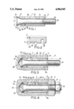
- FIG. 1 is an axially extending view, partly in section, of an expansion dowel assembly embodying the present invention and illustrated in the unexpanded state;
- FIG. 2 is a sectional view of a portion of the expansion dowel assembly illustrated in FIG. 1 and shown on an enlarged scale;
- FIG. 3 is an axially extending view, partly in section, similar to FIG. 1, showing the expansion sleeve of the expansion dowel assembly driven relative to the anchor bolt;
- FIG. 4 is an axially extending view, partly in section, displaying the expansion dowel assembly in the finally anchored condition.
- an expansion dowel assembly is shown made up of an axially elongated anchor bolt 1 and an axially elongated expansion sleeve 2, which laterally encloses at least an axially extending part of the anchor bolt. Further, the expansion sleeve 2 is axially displaceable relative to the anchor bolt for expanding the sleeve.
- Anchor bolt 1 has a leading end 1a, the left-end as viewed in FIG. 1 and a trailing end 1b, the right-end in FIG. 1.
- An intermediate axially extending part of the anchor bolt 1 is provided by a cylindrically shaped shank 1c.
- an axially extending thread 1d is formed for securing a load to the anchor bolt.
- the bolt has an expanding member 1e, extending axially from the leading end of the shank 1c.
- the axially extending surface of the expanding member 1c is formed as a concave curve.
- the radius R of the concavely curved surface is approximately equal to the largest diameter D of the anchor bolt 1, note the leading end 1a of the bolt. Due to its concavely curved surface, the expansion member 1e has a conicity increasing toward the leading end 1a.
- Expansion sleeve 2 has a bore 2a extending through it with an inside diameter corresponding approximately to the outside diameter of the shank 1c so that the sleeve can be displaced axially relative to the bolt.
- Expansion sleeve 2 has axially extending slots 2b extending from its leading end 2c toward its trailing end. 2b facilitate the radial expansion of the sleeve.
- the expansion sleeve 2 At its leading end 2c, has a circumferentially extending cutting tooth 2d on its outer surface. Two additional cutting teeth 2e, 2f are arranged on the outer surface of the expansion sleeve adjacent the cutting tooth 2d and extending toward the trailing end of the sleeve.
- Cutting teeth 2d, 2e, 2f form a substantially sawtooth-shaped section which faces outwardly.
- Each tooth has a steep flank facing toward the leading end 2c and a less steep or inclined flank, relative to the sleeve axis, facing toward the trailing end of the sleeve.
- a cross-sectional reduction formed by a circumferentially extending annular groove 2g located in the outside surface of the sleeve. This cross-sectional reduction provides an improved deformation of the expansion sleeve in the direction in which it is inserted into a borehole.
- the expansion sleeve 2 Adjacent its trailing end, the expansion sleeve 2 has one or more indentations 2h in its outer surface and the indentations in turn form inwardly directed projections on the inside surface of the sleeve. The projections engage in the thread 1d and secure the expansion sleeve 2 on the anchor bolt 1.
- the radially measured depth t of the necked-down portion or valleys forming the cutting teeth 2d, 2e, 2f decreases in the direction from the leading end toward the trailing end. Such decreasing depth t insures that the intermediate spaces between the cutting teeth 2d, 2e, 2f will be filled by the material removed from the surface of the borehole by the cutting teeth and that a wedging action of the material will develop when a force tending to pull the anchor bolt out of the borehole is applied.
- the expansion dowel assembly is inserted into a borehole 3a in a receiving material 3.
- the leading end 1a of the anchor bolt 1 bears against the base 3b of the borehole 3a.
- Expansion sleeve 2 is driven axially into the borehole and moves over the expansion member 1e on the anchor bolt 1 by means of a tubular placing tool 4 shown in dot-dash lines.
- the expansion sleeve 2 is displaced axially relative to the anchor bolt 1, the projections at the inside of the expansion sleeve, formed by the indentations 2h, are sheared off.
- the cutting teeth 2d, 2e, 2f are forced radially outwardly into engagement with the surface of the borehole 3a and remove a part of the material from the borehole surface. Accordingly, a positive locking connection of the expansion sleeve 2 with the receiving material 3 is effected.
- the annular groove 2g in the outer surface of the expansion sleeve 2 and the axially extending slots 2b facilitate the radial expansion of the leading end portion of the expansion sleeve 2.
- a structural component part 5 is fastened to the outside surface of the receiving material 3 by placing the part onto the thread 1d of the anchor bolt 1 and securing the part by a washer 6 and a nut 7 screwed onto the thread 1d.
- a crack 3c in the receiving material 3 is shown at the base 3b of the borehole 3a.
- the opening of this crack 3c makes it possible to draw the expansion bolt 1 into the expansion sleeve 2, with the sleeve being anchored in the receiving material 3 in a positive locking manner.
- the expanding action of the dowel assembly on the crack 3c is slight due to the large conicity of the expanding member 1c at the leading end 1a. After an initial after-expansion of the expansion sleeve, the anchor bolt comes to a stopped position.
Abstract
Description
Claims (5)
Applications Claiming Priority (2)
| Application Number | Priority Date | Filing Date | Title |
|---|---|---|---|
| DE19873731818 DE3731818A1 (en) | 1987-09-22 | 1987-09-22 | SPREADING DOWEL |
| DE3731818 | 1987-09-22 |
Publications (1)
| Publication Number | Publication Date |
|---|---|
| US4984945A true US4984945A (en) | 1991-01-15 |
Family
ID=6336559
Family Applications (1)
| Application Number | Title | Priority Date | Filing Date |
|---|---|---|---|
| US07/247,957 Expired - Lifetime US4984945A (en) | 1987-09-22 | 1988-09-22 | Expansion dowel assembly |
Country Status (9)
| Country | Link |
|---|---|
| US (1) | US4984945A (en) |
| EP (1) | EP0308619B1 (en) |
| JP (2) | JPS6483907A (en) |
| KR (1) | KR910010086B1 (en) |
| AT (1) | ATE73524T1 (en) |
| AU (1) | AU610640B2 (en) |
| CA (1) | CA1320363C (en) |
| DE (2) | DE3731818A1 (en) |
| ES (1) | ES2029501T3 (en) |
Cited By (27)
| Publication number | Priority date | Publication date | Assignee | Title |
|---|---|---|---|---|
| US5213377A (en) * | 1990-08-24 | 1993-05-25 | Friedrich Grohe Armaturenfabrik Gmbh & Co. | Coupling for seating a tube end in a fitting |
| US5609453A (en) * | 1995-02-09 | 1997-03-11 | Fischerwerke, Artur Fischer Gmbh & Co Ag | Expansible plug for anchoring in a drilled hole having an undercut |
| EP0848169A1 (en) * | 1996-12-16 | 1998-06-17 | HILTI Aktiengesellschaft | Self-undercutting anchor |
| US5772372A (en) * | 1996-06-05 | 1998-06-30 | Hilti Aktiengesellschaft | Spreading anchor |
| US5921733A (en) * | 1996-12-16 | 1999-07-13 | Hilti Aktiengesellschaft | Self-cutting undercutting dowel |
| US6135688A (en) * | 1998-10-22 | 2000-10-24 | Hilti Aktiengesellschaft | Undercut self-cutting dowel |
| US6213697B1 (en) | 2000-02-25 | 2001-04-10 | Illinois Tool Works Inc. | Self-cutting expansion anchor |
| AU759062B2 (en) * | 2000-12-20 | 2003-04-03 | Societe De Prospection Et D'inventions Techniques S.P.I.T. | Anchor with an expansible sleeve for hard material |
| US20070243035A1 (en) * | 2006-02-28 | 2007-10-18 | Pratt John D | Mechanically locked blind bolt fastener |
| US20070243037A1 (en) * | 2006-02-28 | 2007-10-18 | Pratt John D | Blind bolt fastener |
| US20070277976A1 (en) * | 2006-06-05 | 2007-12-06 | Kobetsky Robert G | Anchor bolt and annularly grooved expansion sleeve assembly exhibiting high pull-out resistance, particularly under cracked concrete test conditions |
| US20080080945A1 (en) * | 2006-09-28 | 2008-04-03 | Peter Bee | Anchor bar and arrangement for reinforcing existing components against punching shears with such anchor bar |
| US20080213063A1 (en) * | 2006-10-05 | 2008-09-04 | Pratt John D | Dual-action disposable clamp |
| US20090191020A1 (en) * | 2006-10-05 | 2009-07-30 | Pratt John D | Dual action disposable clamp |
| US7744320B2 (en) * | 2006-06-05 | 2010-06-29 | Illinois Tool Works Inc. | Anchor bolt and annularly grooved expansion sleeve assembly exhibiting high pull-out resistance, particularly under cracked concrete test conditions |
| US20100327505A1 (en) * | 2006-10-05 | 2010-12-30 | Pratt John D | Low profile dual-action disposable clamp |
| CN102635616A (en) * | 2012-04-17 | 2012-08-15 | 王春华 | Self-tangency broaching anchor bolt |
| US8287217B2 (en) * | 2007-11-29 | 2012-10-16 | Itw Construction Products Italy S.R.L. Con Unico Socio | Expansion anchor |
| US20130164095A1 (en) * | 2011-12-22 | 2013-06-27 | Hon Hai Precision Industry Co., Ltd. | Fastening assembly |
| US8888425B2 (en) | 2009-03-27 | 2014-11-18 | Monogram Aerospace Fasteners, Inc. | Blind fastener |
| JP2016132901A (en) * | 2015-01-19 | 2016-07-25 | 株式会社ミヤナガ | Anchor bolt |
| US20160230397A1 (en) * | 2013-09-13 | 2016-08-11 | Osman Cavit TURUNC | A development method for mounting natural stones on facade coatings easily |
| CN106351925A (en) * | 2015-07-15 | 2017-01-25 | 费希尔厂有限责任两合公司 | Self-cutting undercut anchor |
| CN110145522A (en) * | 2019-06-19 | 2019-08-20 | 广州花都区乐思富科技有限公司 | A kind of expansion connector |
| US11092180B2 (en) | 2018-05-14 | 2021-08-17 | Carl Barrow | Locking dowel assembly |
| US20220162849A1 (en) * | 2021-12-08 | 2022-05-26 | Black & Decker Inc. | Undercut anchor |
| US11572911B2 (en) | 2015-03-27 | 2023-02-07 | Hilti Aktiengesellschaft | Expansion anchor |
Families Citing this family (18)
| Publication number | Priority date | Publication date | Assignee | Title |
|---|---|---|---|---|
| JPH0462911U (en) * | 1990-10-04 | 1992-05-28 | ||
| DE4116149A1 (en) * | 1991-05-17 | 1992-11-19 | Hilti Ag | SPREADING DOWEL WITH FRICTION REDUCING COATING |
| DE4208834A1 (en) * | 1992-03-19 | 1993-09-23 | Fischer Artur Werke Gmbh | Borehole fitted anchor bolt with cylindrical sleeve - has expanding cone at borehole base to act on adhesive sleeve,on bolt driven in. |
| DE4213941A1 (en) * | 1992-04-28 | 1993-11-11 | Arndt Dr Ing Bergner | Dowels |
| DE9303899U1 (en) * | 1993-03-17 | 1993-05-13 | Liebig, Heinrich, 6102 Pfungstadt, De | |
| DE4344410A1 (en) * | 1993-12-24 | 1995-06-29 | Wuerth Adolf Gmbh & Co Kg | Straddling dowel with bolt and conical-truncated wide part |
| DE4344421A1 (en) * | 1993-12-24 | 1995-06-29 | Wuerth Adolf Gmbh & Co Kg | Straddling dowel with bolt and truncated cone shaped part |
| WO2008022630A1 (en) * | 2006-08-22 | 2008-02-28 | Ccg-Concept Consulting Gmbh | Sleeve anchor |
| DE102007041058A1 (en) * | 2007-08-29 | 2009-03-12 | Zimmer, Günther | Dowel for automatic cover plate rear handle and its injection adhesive method |
| CN102817893A (en) * | 2011-06-09 | 2012-12-12 | 郭振春 | Detachable expansion bolt |
| EP3118469B1 (en) | 2015-07-15 | 2018-03-28 | fischerwerke GmbH & Co. KG | Self-cutting undercut anchor |
| EP3121461B1 (en) * | 2015-07-22 | 2018-09-05 | fischerwerke GmbH & Co. KG | Fastening assembly and expansion anchor |
| DE102016103196A1 (en) * | 2015-07-22 | 2017-01-26 | Fischerwerke Gmbh & Co. Kg | Fastening arrangement and expansion anchor |
| CN106763048A (en) * | 2016-12-25 | 2017-05-31 | 黄传勇 | A kind of expansion bolt |
| CN108506304A (en) * | 2017-04-15 | 2018-09-07 | 裴志胜 | A kind of high strong pluck-resistant anchoring piece with bending slot |
| EP3499054A1 (en) | 2017-12-18 | 2019-06-19 | HILTI Aktiengesellschaft | Expansion anchor comprising adapted annular groove on expanding sleeve |
| EP3499053A1 (en) | 2017-12-18 | 2019-06-19 | HILTI Aktiengesellschaft | Expansion anchor comprising broad annular groove on expanding sleeve |
| DE102021107001A1 (en) * | 2020-04-02 | 2021-10-07 | Fischerwerke Gmbh & Co. Kg | Undercut anchor and method of anchoring it |
Citations (11)
| Publication number | Priority date | Publication date | Assignee | Title |
|---|---|---|---|---|
| US688756A (en) * | 1900-05-24 | 1901-12-10 | Jacob W Tripp | Expansion-bolt. |
| US2470924A (en) * | 1946-08-29 | 1949-05-24 | South Chester Corp | Fastening device |
| FR1297330A (en) * | 1961-05-19 | 1962-06-29 | Louis Colin & Fils | Method of fixing mechanical parts on supports mainly soft material supports |
| NL6508503A (en) * | 1965-07-01 | 1967-01-02 | ||
| FR1469966A (en) * | 1965-03-02 | 1967-02-17 | Anchor for fixing objects in materials such as wood | |
| DE2828497A1 (en) * | 1978-06-29 | 1980-01-17 | Fischer Artur Dr H C | METAL SPREADING DOWEL |
| DE3134876A1 (en) * | 1981-09-03 | 1983-03-17 | Artur Dr.H.C. 7244 Waldachtal Fischer | Expanding dowel for anchoring in bores which are produced such that they widen conically inwards |
| GB2109886A (en) * | 1981-11-20 | 1983-06-08 | Hilti Ag | Anchor bolt |
| DE3315451A1 (en) * | 1983-04-28 | 1984-10-31 | Artur Dr.H.C. 7244 Waldachtal Fischer | Expandable dowel for anchoring in drilled holes which are produced such that they expand conically inwards |
| US4560311A (en) * | 1982-12-14 | 1985-12-24 | Hilti Aktiengesellschaft | Expansion dowel assembly |
| US4640654A (en) * | 1984-06-01 | 1987-02-03 | Artur Fischer | Anchor |
Family Cites Families (7)
| Publication number | Priority date | Publication date | Assignee | Title |
|---|---|---|---|---|
| GB1070692A (en) * | 1963-10-14 | 1967-06-01 | Phillips Drill Co | Expansion stud anchor |
| US3448651A (en) * | 1967-06-02 | 1969-06-10 | Usm Corp | Expansion bolts |
| DE2221267C3 (en) * | 1971-04-30 | 1978-10-05 | Giorgio Mailand Feige (Italien) | Expansion anchor |
| ZA746402B (en) * | 1974-04-30 | 1975-10-29 | Rawlplug Co Ltd | Bolt anchoring device |
| JPS55155905A (en) * | 1980-01-31 | 1980-12-04 | Okabe Kk | Manufacture of cylindrical body for anchor |
| DE3025816A1 (en) * | 1980-07-08 | 1982-02-04 | Werkzeugfabrik Fritz Mächtle GmbH & Co KG, 7015 Korntal | METHOD FOR FASTENING LOADS BY SPREADING ANCHOR AND SPREADING ANCHOR FOR CARRYING OUT THIS METHOD |
| DE3535262A1 (en) * | 1985-10-03 | 1987-04-09 | Upat Max Langensiepen Kg | SPREADING ANCHOR |
-
1987
- 1987-09-22 DE DE19873731818 patent/DE3731818A1/en not_active Withdrawn
-
1988
- 1988-07-27 DE DE8888112085T patent/DE3869029D1/en not_active Expired - Lifetime
- 1988-07-27 ES ES198888112085T patent/ES2029501T3/en not_active Expired - Lifetime
- 1988-07-27 AT AT88112085T patent/ATE73524T1/en not_active IP Right Cessation
- 1988-07-27 EP EP88112085A patent/EP0308619B1/en not_active Expired - Lifetime
- 1988-08-29 JP JP63212630A patent/JPS6483907A/en active Pending
- 1988-09-09 AU AU22026/88A patent/AU610640B2/en not_active Ceased
- 1988-09-21 CA CA000578011A patent/CA1320363C/en not_active Expired - Fee Related
- 1988-09-21 KR KR1019880012186A patent/KR910010086B1/en not_active IP Right Cessation
- 1988-09-22 US US07/247,957 patent/US4984945A/en not_active Expired - Lifetime
-
1997
- 1997-03-13 JP JP1997001653U patent/JP2568893Y2/en not_active Expired - Lifetime
Patent Citations (11)
| Publication number | Priority date | Publication date | Assignee | Title |
|---|---|---|---|---|
| US688756A (en) * | 1900-05-24 | 1901-12-10 | Jacob W Tripp | Expansion-bolt. |
| US2470924A (en) * | 1946-08-29 | 1949-05-24 | South Chester Corp | Fastening device |
| FR1297330A (en) * | 1961-05-19 | 1962-06-29 | Louis Colin & Fils | Method of fixing mechanical parts on supports mainly soft material supports |
| FR1469966A (en) * | 1965-03-02 | 1967-02-17 | Anchor for fixing objects in materials such as wood | |
| NL6508503A (en) * | 1965-07-01 | 1967-01-02 | ||
| DE2828497A1 (en) * | 1978-06-29 | 1980-01-17 | Fischer Artur Dr H C | METAL SPREADING DOWEL |
| DE3134876A1 (en) * | 1981-09-03 | 1983-03-17 | Artur Dr.H.C. 7244 Waldachtal Fischer | Expanding dowel for anchoring in bores which are produced such that they widen conically inwards |
| GB2109886A (en) * | 1981-11-20 | 1983-06-08 | Hilti Ag | Anchor bolt |
| US4560311A (en) * | 1982-12-14 | 1985-12-24 | Hilti Aktiengesellschaft | Expansion dowel assembly |
| DE3315451A1 (en) * | 1983-04-28 | 1984-10-31 | Artur Dr.H.C. 7244 Waldachtal Fischer | Expandable dowel for anchoring in drilled holes which are produced such that they expand conically inwards |
| US4640654A (en) * | 1984-06-01 | 1987-02-03 | Artur Fischer | Anchor |
Cited By (45)
| Publication number | Priority date | Publication date | Assignee | Title |
|---|---|---|---|---|
| US5213377A (en) * | 1990-08-24 | 1993-05-25 | Friedrich Grohe Armaturenfabrik Gmbh & Co. | Coupling for seating a tube end in a fitting |
| US5609453A (en) * | 1995-02-09 | 1997-03-11 | Fischerwerke, Artur Fischer Gmbh & Co Ag | Expansible plug for anchoring in a drilled hole having an undercut |
| US5772372A (en) * | 1996-06-05 | 1998-06-30 | Hilti Aktiengesellschaft | Spreading anchor |
| CN1100214C (en) * | 1996-06-05 | 2003-01-29 | 希尔蒂股份公司 | Inverse cutting rockbolt |
| EP0848169A1 (en) * | 1996-12-16 | 1998-06-17 | HILTI Aktiengesellschaft | Self-undercutting anchor |
| KR19980063644A (en) * | 1996-12-16 | 1998-10-07 | 빌디롤란트 | Undercut Dowwell with automatic cutting |
| US5911550A (en) * | 1996-12-16 | 1999-06-15 | Hilti Aktiengesellschaft | Self-cutting dowel |
| US5921733A (en) * | 1996-12-16 | 1999-07-13 | Hilti Aktiengesellschaft | Self-cutting undercutting dowel |
| US6135688A (en) * | 1998-10-22 | 2000-10-24 | Hilti Aktiengesellschaft | Undercut self-cutting dowel |
| US6213697B1 (en) | 2000-02-25 | 2001-04-10 | Illinois Tool Works Inc. | Self-cutting expansion anchor |
| AU759062B2 (en) * | 2000-12-20 | 2003-04-03 | Societe De Prospection Et D'inventions Techniques S.P.I.T. | Anchor with an expansible sleeve for hard material |
| US6652207B2 (en) * | 2000-12-20 | 2003-11-25 | Société de Prospection et d'Inventions techniques SPIT | Anchor for hard material having an expansible sleeve with a deformable end portion |
| US7857563B2 (en) * | 2006-02-28 | 2010-12-28 | Monogram Aerospace Fasteners, Inc. | Mechanically locked blind bolt fastener |
| US20070243037A1 (en) * | 2006-02-28 | 2007-10-18 | Pratt John D | Blind bolt fastener |
| US20070243035A1 (en) * | 2006-02-28 | 2007-10-18 | Pratt John D | Mechanically locked blind bolt fastener |
| AU2007259322B2 (en) * | 2006-06-05 | 2011-10-27 | Illinois Tool Works Inc. | Anchor bolt and annularly grooved expansion sleeve assembly exhibiting high pull-out resistance, particularly under cracked concrete test conditions |
| US20070277976A1 (en) * | 2006-06-05 | 2007-12-06 | Kobetsky Robert G | Anchor bolt and annularly grooved expansion sleeve assembly exhibiting high pull-out resistance, particularly under cracked concrete test conditions |
| US8491244B2 (en) | 2006-06-05 | 2013-07-23 | Illinois Tool Works Inc. | Anchor bolt and annularly grooved expansion sleeve assembly exhibiting high pull-out resistance, particularly under cracked concrete test conditions |
| US8302276B2 (en) | 2006-06-05 | 2012-11-06 | Illinois Tool Works Inc. | Anchor bolt and annularly grooved expansion sleeve assembly exhibiting high pull-out resistance, particularly under cracked concrete test conditions |
| US7744320B2 (en) * | 2006-06-05 | 2010-06-29 | Illinois Tool Works Inc. | Anchor bolt and annularly grooved expansion sleeve assembly exhibiting high pull-out resistance, particularly under cracked concrete test conditions |
| US20100229641A1 (en) * | 2006-06-05 | 2010-09-16 | Illinois Tool Works Inc. | Anchor bolt and annularly grooved expansion sleeve assembly exhibiting high pull-out resistance, particularly under cracked concrete test conditions |
| US7811037B2 (en) * | 2006-06-05 | 2010-10-12 | Illinois Tool Works Inc. | Anchor bolt and annularly grooved expansion sleeve assembly exhibiting high pull-out resistance, particularly under cracked concrete test conditions |
| US20080080945A1 (en) * | 2006-09-28 | 2008-04-03 | Peter Bee | Anchor bar and arrangement for reinforcing existing components against punching shears with such anchor bar |
| US20100327505A1 (en) * | 2006-10-05 | 2010-12-30 | Pratt John D | Low profile dual-action disposable clamp |
| US8608417B2 (en) | 2006-10-05 | 2013-12-17 | Monogram Aerospace Fasteners, Inc. | Dual action disposable clamp |
| US20090226278A1 (en) * | 2006-10-05 | 2009-09-10 | Pratt John D | Deformable sleeve for a dual-action clamp |
| US8398345B2 (en) | 2006-10-05 | 2013-03-19 | Monogram Aerospace Fasteners, Inc. | Low profile dual-action disposable clamp |
| US20090191020A1 (en) * | 2006-10-05 | 2009-07-30 | Pratt John D | Dual action disposable clamp |
| US20080213063A1 (en) * | 2006-10-05 | 2008-09-04 | Pratt John D | Dual-action disposable clamp |
| US8511952B2 (en) | 2006-10-05 | 2013-08-20 | Monogram Aerospace Fasteners, Inc. | Dual-action disposable clamp |
| US8517649B2 (en) | 2006-10-05 | 2013-08-27 | Monogram Aerospace Fasteners, Inc. | Dual-action disposable clamp |
| US8287217B2 (en) * | 2007-11-29 | 2012-10-16 | Itw Construction Products Italy S.R.L. Con Unico Socio | Expansion anchor |
| US8888425B2 (en) | 2009-03-27 | 2014-11-18 | Monogram Aerospace Fasteners, Inc. | Blind fastener |
| US20130164095A1 (en) * | 2011-12-22 | 2013-06-27 | Hon Hai Precision Industry Co., Ltd. | Fastening assembly |
| US8834084B2 (en) * | 2011-12-22 | 2014-09-16 | Fu Tai Hua Industry (Shenzhen) Co., Ltd. | Fastening assembly |
| CN102635616A (en) * | 2012-04-17 | 2012-08-15 | 王春华 | Self-tangency broaching anchor bolt |
| US20160230397A1 (en) * | 2013-09-13 | 2016-08-11 | Osman Cavit TURUNC | A development method for mounting natural stones on facade coatings easily |
| JP2016132901A (en) * | 2015-01-19 | 2016-07-25 | 株式会社ミヤナガ | Anchor bolt |
| US11572911B2 (en) | 2015-03-27 | 2023-02-07 | Hilti Aktiengesellschaft | Expansion anchor |
| CN106351925A (en) * | 2015-07-15 | 2017-01-25 | 费希尔厂有限责任两合公司 | Self-cutting undercut anchor |
| CN106351925B (en) * | 2015-07-15 | 2019-05-17 | 费希尔厂有限责任两合公司 | That autotomys cuts bottom anchor bolt |
| US11092180B2 (en) | 2018-05-14 | 2021-08-17 | Carl Barrow | Locking dowel assembly |
| CN110145522A (en) * | 2019-06-19 | 2019-08-20 | 广州花都区乐思富科技有限公司 | A kind of expansion connector |
| CN110145522B (en) * | 2019-06-19 | 2024-04-02 | 广州花都区乐思富科技有限公司 | Expansion connecting piece |
| US20220162849A1 (en) * | 2021-12-08 | 2022-05-26 | Black & Decker Inc. | Undercut anchor |
Also Published As
| Publication number | Publication date |
|---|---|
| KR910010086B1 (en) | 1991-12-14 |
| AU610640B2 (en) | 1991-05-23 |
| ES2029501T3 (en) | 1992-08-16 |
| CA1320363C (en) | 1993-07-20 |
| KR890005400A (en) | 1989-05-13 |
| DE3869029D1 (en) | 1992-04-16 |
| JPH09498U (en) | 1997-09-22 |
| AU2202688A (en) | 1989-03-23 |
| DE3731818A1 (en) | 1989-03-30 |
| EP0308619A1 (en) | 1989-03-29 |
| JP2568893Y2 (en) | 1998-04-15 |
| EP0308619B1 (en) | 1992-03-11 |
| JPS6483907A (en) | 1989-03-29 |
| ATE73524T1 (en) | 1992-03-15 |
Similar Documents
| Publication | Publication Date | Title |
|---|---|---|
| US4984945A (en) | Expansion dowel assembly | |
| US4929134A (en) | Expansion dowel assembly | |
| US4692076A (en) | Expansion dowel with anchored state indicator | |
| CA1250159A (en) | Expansion dowel assembly | |
| EP0834658B1 (en) | Bolt anchoring device | |
| US6829871B1 (en) | Wedge anchor for concrete | |
| US6062784A (en) | Spreading anchor | |
| US4898505A (en) | Expansion dowel assembly with an expansion cone displaceable into an expansion sleeve | |
| US4560311A (en) | Expansion dowel assembly | |
| US4275637A (en) | Fastening element assembly | |
| GB2223818A (en) | Method for tight sealing of a hole and hole arrangement | |
| US3750526A (en) | Expansion bolt with unitary wedge assembly | |
| US4147444A (en) | Expansion dowel | |
| EP0124489A1 (en) | Wall dowel | |
| US4770580A (en) | Expansible anchoring plug | |
| US4611963A (en) | Expansion dowel with an expansion wedge and an annular expansion member | |
| US4634326A (en) | Expansion anchor | |
| US5791846A (en) | Expansion dowel | |
| US5688066A (en) | Expansion dowel | |
| US4773803A (en) | Expansion dowel assembly with extension on expansion member | |
| US4702656A (en) | Expansion bolt assembly | |
| RU2230947C2 (en) | Expansion bolt | |
| US6302627B1 (en) | Multipart dowel for a removable anchor | |
| US4109556A (en) | Expansion dowel | |
| SK116396A3 (en) | Expandable clamp |
Legal Events
| Date | Code | Title | Description |
|---|---|---|---|
| AS | Assignment |
Owner name: HILTI AKTIENGESELLSCHAFT, F1-9494 SCHAAN FURSTENTU Free format text: ASSIGNMENT OF ASSIGNORS INTEREST.;ASSIGNOR:BERGNER, ARNDT;REEL/FRAME:004974/0460 Effective date: 19881005 Owner name: HILTI AKTIENGESELLSCHAFT, LIECHTENSTEIN Free format text: ASSIGNMENT OF ASSIGNORS INTEREST;ASSIGNOR:BERGNER, ARNDT;REEL/FRAME:004974/0460 Effective date: 19881005 |
|
| STCF | Information on status: patent grant |
Free format text: PATENTED CASE |
|
| FPAY | Fee payment |
Year of fee payment: 4 |
|
| FPAY | Fee payment |
Year of fee payment: 8 |
|
| FEPP | Fee payment procedure |
Free format text: PAYOR NUMBER ASSIGNED (ORIGINAL EVENT CODE: ASPN); ENTITY STATUS OF PATENT OWNER: LARGE ENTITY |
|
| FPAY | Fee payment |
Year of fee payment: 12 |