US4990983A - Radiation hardened field oxides for NMOS and CMOS-bulk and process for forming - Google Patents
Radiation hardened field oxides for NMOS and CMOS-bulk and process for forming Download PDFInfo
- Publication number
- US4990983A US4990983A US07/130,914 US13091487A US4990983A US 4990983 A US4990983 A US 4990983A US 13091487 A US13091487 A US 13091487A US 4990983 A US4990983 A US 4990983A
- Authority
- US
- United States
- Prior art keywords
- field oxide
- region
- oxide
- thin
- field
- Prior art date
- Legal status (The legal status is an assumption and is not a legal conclusion. Google has not performed a legal analysis and makes no representation as to the accuracy of the status listed.)
- Expired - Fee Related
Links
Images


Classifications
-
- H—ELECTRICITY
- H01—ELECTRIC ELEMENTS
- H01L—SEMICONDUCTOR DEVICES NOT COVERED BY CLASS H10
- H01L21/00—Processes or apparatus adapted for the manufacture or treatment of semiconductor or solid state devices or of parts thereof
- H01L21/70—Manufacture or treatment of devices consisting of a plurality of solid state components formed in or on a common substrate or of parts thereof; Manufacture of integrated circuit devices or of parts thereof
- H01L21/71—Manufacture of specific parts of devices defined in group H01L21/70
- H01L21/76—Making of isolation regions between components
- H01L21/762—Dielectric regions, e.g. EPIC dielectric isolation, LOCOS; Trench refilling techniques, SOI technology, use of channel stoppers
- H01L21/76202—Dielectric regions, e.g. EPIC dielectric isolation, LOCOS; Trench refilling techniques, SOI technology, use of channel stoppers using a local oxidation of silicon, e.g. LOCOS, SWAMI, SILO
- H01L21/76213—Dielectric regions, e.g. EPIC dielectric isolation, LOCOS; Trench refilling techniques, SOI technology, use of channel stoppers using a local oxidation of silicon, e.g. LOCOS, SWAMI, SILO introducing electrical inactive or active impurities in the local oxidation region, e.g. to alter LOCOS oxide growth characteristics or for additional isolation purpose
- H01L21/76216—Dielectric regions, e.g. EPIC dielectric isolation, LOCOS; Trench refilling techniques, SOI technology, use of channel stoppers using a local oxidation of silicon, e.g. LOCOS, SWAMI, SILO introducing electrical inactive or active impurities in the local oxidation region, e.g. to alter LOCOS oxide growth characteristics or for additional isolation purpose introducing electrical active impurities in the local oxidation region for the sole purpose of creating channel stoppers
-
- H—ELECTRICITY
- H01—ELECTRIC ELEMENTS
- H01L—SEMICONDUCTOR DEVICES NOT COVERED BY CLASS H10
- H01L27/00—Devices consisting of a plurality of semiconductor or other solid-state components formed in or on a common substrate
- H01L27/02—Devices consisting of a plurality of semiconductor or other solid-state components formed in or on a common substrate including semiconductor components specially adapted for rectifying, oscillating, amplifying or switching and having at least one potential-jump barrier or surface barrier; including integrated passive circuit elements with at least one potential-jump barrier or surface barrier
- H01L27/04—Devices consisting of a plurality of semiconductor or other solid-state components formed in or on a common substrate including semiconductor components specially adapted for rectifying, oscillating, amplifying or switching and having at least one potential-jump barrier or surface barrier; including integrated passive circuit elements with at least one potential-jump barrier or surface barrier the substrate being a semiconductor body
- H01L27/08—Devices consisting of a plurality of semiconductor or other solid-state components formed in or on a common substrate including semiconductor components specially adapted for rectifying, oscillating, amplifying or switching and having at least one potential-jump barrier or surface barrier; including integrated passive circuit elements with at least one potential-jump barrier or surface barrier the substrate being a semiconductor body including only semiconductor components of a single kind
- H01L27/085—Devices consisting of a plurality of semiconductor or other solid-state components formed in or on a common substrate including semiconductor components specially adapted for rectifying, oscillating, amplifying or switching and having at least one potential-jump barrier or surface barrier; including integrated passive circuit elements with at least one potential-jump barrier or surface barrier the substrate being a semiconductor body including only semiconductor components of a single kind including field-effect components only
- H01L27/088—Devices consisting of a plurality of semiconductor or other solid-state components formed in or on a common substrate including semiconductor components specially adapted for rectifying, oscillating, amplifying or switching and having at least one potential-jump barrier or surface barrier; including integrated passive circuit elements with at least one potential-jump barrier or surface barrier the substrate being a semiconductor body including only semiconductor components of a single kind including field-effect components only the components being field-effect transistors with insulated gate
- H01L27/092—Devices consisting of a plurality of semiconductor or other solid-state components formed in or on a common substrate including semiconductor components specially adapted for rectifying, oscillating, amplifying or switching and having at least one potential-jump barrier or surface barrier; including integrated passive circuit elements with at least one potential-jump barrier or surface barrier the substrate being a semiconductor body including only semiconductor components of a single kind including field-effect components only the components being field-effect transistors with insulated gate complementary MIS field-effect transistors
- H01L27/0928—Devices consisting of a plurality of semiconductor or other solid-state components formed in or on a common substrate including semiconductor components specially adapted for rectifying, oscillating, amplifying or switching and having at least one potential-jump barrier or surface barrier; including integrated passive circuit elements with at least one potential-jump barrier or surface barrier the substrate being a semiconductor body including only semiconductor components of a single kind including field-effect components only the components being field-effect transistors with insulated gate complementary MIS field-effect transistors comprising both N- and P- wells in the substrate, e.g. twin-tub
-
- Y—GENERAL TAGGING OF NEW TECHNOLOGICAL DEVELOPMENTS; GENERAL TAGGING OF CROSS-SECTIONAL TECHNOLOGIES SPANNING OVER SEVERAL SECTIONS OF THE IPC; TECHNICAL SUBJECTS COVERED BY FORMER USPC CROSS-REFERENCE ART COLLECTIONS [XRACs] AND DIGESTS
- Y10—TECHNICAL SUBJECTS COVERED BY FORMER USPC
- Y10S—TECHNICAL SUBJECTS COVERED BY FORMER USPC CROSS-REFERENCE ART COLLECTIONS [XRACs] AND DIGESTS
- Y10S257/00—Active solid-state devices, e.g. transistors, solid-state diodes
- Y10S257/906—Dram with capacitor electrodes used for accessing, e.g. bit line is capacitor plate
Definitions
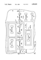
- An insulating layer 78 (FIG. 13) is deposited next (PSG or BPSG or equivalent), and contact holes (e.g. 79) opened, as shown in FIG. 13.
Abstract
Description
              TABLE I
______________________________________
Hardness characteristics of thin-oxide notched regions
with degenerate regions in semiconductor region below it.
Pre-Rad       Post-Rad
t.sub.1
       ΔV.sub.t
                  30 KRADS       Δ1000 KRADS
A      (V)        V.sub.t
                         V.sub.t V.sub.t
                                      V.sub.t
______________________________________
1000    54        0.6     53      2    52
2000   107        2.5    104      9   105
3000   161        6.0    155     20   140
4000   215        10.0   205     34   180
5000   270        16.0   254     54   215
______________________________________
______________________________________
t.sub.2
______________________________________
 8000   29       -40.0   <0      -140  <0
10000   37       -63.0   <0      -215  <0
12000   44       -90.0   <0      -310  <0
______________________________________
Claims (6)
Priority Applications (1)
| Application Number | Priority Date | Filing Date | Title |
|---|---|---|---|
| US07/130,914 US4990983A (en) | 1986-10-31 | 1987-12-07 | Radiation hardened field oxides for NMOS and CMOS-bulk and process for forming |
Applications Claiming Priority (2)
| Application Number | Priority Date | Filing Date | Title |
|---|---|---|---|
| US92631986A | 1986-10-31 | 1986-10-31 | |
| US07/130,914 US4990983A (en) | 1986-10-31 | 1987-12-07 | Radiation hardened field oxides for NMOS and CMOS-bulk and process for forming |
Related Parent Applications (1)
| Application Number | Title | Priority Date | Filing Date |
|---|---|---|---|
| US92631986A Division | 1986-10-31 | 1986-10-31 |
Publications (1)
| Publication Number | Publication Date |
|---|---|
| US4990983A true US4990983A (en) | 1991-02-05 |
Family
ID=26828968
Family Applications (1)
| Application Number | Title | Priority Date | Filing Date |
|---|---|---|---|
| US07/130,914 Expired - Fee Related US4990983A (en) | 1986-10-31 | 1987-12-07 | Radiation hardened field oxides for NMOS and CMOS-bulk and process for forming |
Country Status (1)
| Country | Link |
|---|---|
| US (1) | US4990983A (en) |
Cited By (9)
| Publication number | Priority date | Publication date | Assignee | Title |
|---|---|---|---|---|
| US5239195A (en) * | 1990-05-17 | 1993-08-24 | Hello S.A. | Mos transistor with high threshold voltage |
| US5422505A (en) * | 1990-10-17 | 1995-06-06 | Kabushiki Kaisha Toshiba | FET having gate insulating films whose thickness is different depending on portions |
| US5599728A (en) * | 1994-04-07 | 1997-02-04 | Regents Of The University Of California | Method of fabricating a self-aligned high speed MOSFET device |
| US5650654A (en) * | 1994-12-30 | 1997-07-22 | International Business Machines Corporation | MOSFET device having controlled parasitic isolation threshold voltage |
| US5670816A (en) * | 1989-04-07 | 1997-09-23 | Kabushiki Kaisha Toshiba | Semiconductor device |
| US5675171A (en) * | 1995-04-20 | 1997-10-07 | Nec Corporation | Integrated insulated gate field effect transistors with thin insulation region between field insulation regions |
| US6624495B2 (en) * | 1997-04-23 | 2003-09-23 | Altera Corporation | Adjustable threshold isolation transistor |
| US20040262641A1 (en) * | 1999-01-14 | 2004-12-30 | Rhodes Howard E. | Trench isolation for semiconductor devices |
| US9281232B2 (en) | 2013-10-21 | 2016-03-08 | Texas Instruments Incorporated | Device having improved radiation hardness and high breakdown voltages |
Citations (11)
| Publication number | Priority date | Publication date | Assignee | Title |
|---|---|---|---|---|
| US3450960A (en) * | 1965-09-29 | 1969-06-17 | Ibm | Insulated-gate field effect transistor with nonplanar gate electrode structure for optimizing transconductance |
| US3751722A (en) * | 1971-04-30 | 1973-08-07 | Standard Microsyst Smc | Mos integrated circuit with substrate containing selectively formed resistivity regions |
| US3892609A (en) * | 1971-10-07 | 1975-07-01 | Hughes Aircraft Co | Production of mis integrated devices with high inversion voltage to threshold voltage ratios |
| US3974516A (en) * | 1970-11-21 | 1976-08-10 | U.S. Philips Corporation | Method of manufacturing a semiconductor device having at least one insulated gate field effect transistor, and semiconductor device manufactured by using the method |
| JPS5237775A (en) * | 1975-09-19 | 1977-03-23 | Mitsubishi Electric Corp | Complementary semiconductor device |
| US4063274A (en) * | 1976-12-10 | 1977-12-13 | Rca Corporation | Integrated circuit device including both N-channel and P-channel insulated gate field effect transistors |
| JPS5651870A (en) * | 1979-10-05 | 1981-05-09 | Oki Electric Ind Co Ltd | Manufacture of complementary type mos semiconductor device |
| US4282648A (en) * | 1980-03-24 | 1981-08-11 | Intel Corporation | CMOS process |
| US4458262A (en) * | 1980-05-27 | 1984-07-03 | Supertex, Inc. | CMOS Device with ion-implanted channel-stop region and fabrication method therefor |
| US4613886A (en) * | 1981-07-09 | 1986-09-23 | Intel Corporation | CMOS static memory cell |
| US4748489A (en) * | 1985-03-22 | 1988-05-31 | Nec Corporation | Integrated circuit semiconductor device having improved isolation region |
-
1987
- 1987-12-07 US US07/130,914 patent/US4990983A/en not_active Expired - Fee Related
Patent Citations (11)
| Publication number | Priority date | Publication date | Assignee | Title |
|---|---|---|---|---|
| US3450960A (en) * | 1965-09-29 | 1969-06-17 | Ibm | Insulated-gate field effect transistor with nonplanar gate electrode structure for optimizing transconductance |
| US3974516A (en) * | 1970-11-21 | 1976-08-10 | U.S. Philips Corporation | Method of manufacturing a semiconductor device having at least one insulated gate field effect transistor, and semiconductor device manufactured by using the method |
| US3751722A (en) * | 1971-04-30 | 1973-08-07 | Standard Microsyst Smc | Mos integrated circuit with substrate containing selectively formed resistivity regions |
| US3892609A (en) * | 1971-10-07 | 1975-07-01 | Hughes Aircraft Co | Production of mis integrated devices with high inversion voltage to threshold voltage ratios |
| JPS5237775A (en) * | 1975-09-19 | 1977-03-23 | Mitsubishi Electric Corp | Complementary semiconductor device |
| US4063274A (en) * | 1976-12-10 | 1977-12-13 | Rca Corporation | Integrated circuit device including both N-channel and P-channel insulated gate field effect transistors |
| JPS5651870A (en) * | 1979-10-05 | 1981-05-09 | Oki Electric Ind Co Ltd | Manufacture of complementary type mos semiconductor device |
| US4282648A (en) * | 1980-03-24 | 1981-08-11 | Intel Corporation | CMOS process |
| US4458262A (en) * | 1980-05-27 | 1984-07-03 | Supertex, Inc. | CMOS Device with ion-implanted channel-stop region and fabrication method therefor |
| US4613886A (en) * | 1981-07-09 | 1986-09-23 | Intel Corporation | CMOS static memory cell |
| US4748489A (en) * | 1985-03-22 | 1988-05-31 | Nec Corporation | Integrated circuit semiconductor device having improved isolation region |
Cited By (16)
| Publication number | Priority date | Publication date | Assignee | Title |
|---|---|---|---|---|
| US5670816A (en) * | 1989-04-07 | 1997-09-23 | Kabushiki Kaisha Toshiba | Semiconductor device |
| US5239195A (en) * | 1990-05-17 | 1993-08-24 | Hello S.A. | Mos transistor with high threshold voltage |
| US5422505A (en) * | 1990-10-17 | 1995-06-06 | Kabushiki Kaisha Toshiba | FET having gate insulating films whose thickness is different depending on portions |
| US5599728A (en) * | 1994-04-07 | 1997-02-04 | Regents Of The University Of California | Method of fabricating a self-aligned high speed MOSFET device |
| US5650654A (en) * | 1994-12-30 | 1997-07-22 | International Business Machines Corporation | MOSFET device having controlled parasitic isolation threshold voltage |
| US5675171A (en) * | 1995-04-20 | 1997-10-07 | Nec Corporation | Integrated insulated gate field effect transistors with thin insulation region between field insulation regions |
| US6943072B2 (en) | 1997-04-23 | 2005-09-13 | Altera Corporation | Adjustable threshold isolation transistor |
| US6624495B2 (en) * | 1997-04-23 | 2003-09-23 | Altera Corporation | Adjustable threshold isolation transistor |
| US20040018698A1 (en) * | 1997-04-23 | 2004-01-29 | Altera Corporation | Adjustable threshold isolation transistor |
| US20040262641A1 (en) * | 1999-01-14 | 2004-12-30 | Rhodes Howard E. | Trench isolation for semiconductor devices |
| US6856001B2 (en) * | 1999-01-14 | 2005-02-15 | Micron Technology, Inc. | Trench isolation for semiconductor devices |
| US7071531B2 (en) | 1999-01-14 | 2006-07-04 | Micron Technology, Inc. | Trench isolation for semiconductor devices |
| US20060244015A1 (en) * | 1999-01-14 | 2006-11-02 | Rhodes Howard E | Trench isolation for semiconductor devices |
| US9281232B2 (en) | 2013-10-21 | 2016-03-08 | Texas Instruments Incorporated | Device having improved radiation hardness and high breakdown voltages |
| US9620586B2 (en) | 2013-10-21 | 2017-04-11 | Texas Instruments Incorporated | Device having improved radiation hardness and high breakdown voltages |
| US9653544B2 (en) | 2013-10-21 | 2017-05-16 | Texas Instruments Incorporated | Methods for fabricating radiation hardened MOS devices |
Similar Documents
| Publication | Publication Date | Title |
|---|---|---|
| US6538278B1 (en) | CMOS integrated circuit having PMOS and NMOS devices with different gate dielectric layers | |
| US4385947A (en) | Method for fabricating CMOS in P substrate with single guard ring using local oxidation | |
| US5763922A (en) | CMOS integrated circuit having PMOS and NMOS devices with different gate dielectric layers | |
| KR0173111B1 (en) | Trench gate metal oxide semiconductor field effect transistor | |
| US4435895A (en) | Process for forming complementary integrated circuit devices | |
| US4574467A (en) | N- well CMOS process on a P substrate with double field guard rings and a PMOS buried channel | |
| US5137837A (en) | Radiation-hard, high-voltage semiconductive device structure fabricated on SOI substrate | |
| US4637124A (en) | Process for fabricating semiconductor integrated circuit device | |
| US4891326A (en) | Semiconductor device and a process for manufacturing the same | |
| US6787849B2 (en) | Semiconductor devices and methods of manufacturing the same | |
| US5970338A (en) | Method of producing an EEPROM semiconductor structure | |
| JPH0691201B2 (en) | Method for manufacturing CMOS semiconductor device | |
| KR100397096B1 (en) | Semiconductor device and manufacturing method thereof | |
| US4994407A (en) | Radiation hardened field oxides for NMOS and CMOS-bulk and process for forming | |
| US4990983A (en) | Radiation hardened field oxides for NMOS and CMOS-bulk and process for forming | |
| US5506438A (en) | Semiconductor device with two different threshold voltages | |
| US4682408A (en) | Method for making field oxide region with self-aligned channel stop implantation | |
| JPS60100469A (en) | Semiconductor device | |
| EP0263287A2 (en) | Forming a capacitor in an integrated circuit | |
| JPS60123055A (en) | Semiconductor device and manufacture thereof | |
| JPH05865B2 (en) | ||
| US5486482A (en) | Process for fabricating metal-gate CMOS transistor | |
| KR0166991B1 (en) | Method of manufacturing a semiconductor device provided with an isolation region | |
| JPH01155654A (en) | Complementary type integrated circuit | |
| JPS62262462A (en) | Semiconductor device |
Legal Events
| Date | Code | Title | Description |
|---|---|---|---|
| CC | Certificate of correction | ||
| FEPP | Fee payment procedure |
Free format text: PAYOR NUMBER ASSIGNED (ORIGINAL EVENT CODE: ASPN); ENTITY STATUS OF PATENT OWNER: LARGE ENTITY |
|
| FPAY | Fee payment |
Year of fee payment: 4 |
|
| REMI | Maintenance fee reminder mailed | ||
| FPAY | Fee payment |
Year of fee payment: 8 |
|
| SULP | Surcharge for late payment | ||
| AS | Assignment |
Owner name: CREDIT SUISSE FIRST BOSTON, NEW YORK Free format text: SECURITY INTEREST;ASSIGNORS:CONEXANT SYSTEMS, INC.;BROOKTREE CORPORATION;BROOKTREE WORLDWIDE SALES CORPORATION;AND OTHERS;REEL/FRAME:009719/0537 Effective date: 19981221 |
|
| AS | Assignment |
Owner name: CONEXANT SYSTEMS, INC., CALIFORNIA Free format text: ASSIGNMENT OF ASSIGNORS INTEREST;ASSIGNOR:ROCKWELL SCIENCE CENTER, LLC;REEL/FRAME:010415/0761 Effective date: 19981210 |
|
| AS | Assignment |
Owner name: CONEXANT SYSTEMS, INC., CALIFORNIA Free format text: RELEASE OF SECURITY INTEREST;ASSIGNOR:CREDIT SUISSE FIRST BOSTON;REEL/FRAME:012252/0413 Effective date: 20011018 Owner name: BROOKTREE CORPORATION, CALIFORNIA Free format text: RELEASE OF SECURITY INTEREST;ASSIGNOR:CREDIT SUISSE FIRST BOSTON;REEL/FRAME:012252/0413 Effective date: 20011018 Owner name: BROOKTREE WORLDWIDE SALES CORPORATION, CALIFORNIA Free format text: RELEASE OF SECURITY INTEREST;ASSIGNOR:CREDIT SUISSE FIRST BOSTON;REEL/FRAME:012252/0413 Effective date: 20011018 Owner name: CONEXANT SYSTEMS WORLDWIDE, INC., CALIFORNIA Free format text: RELEASE OF SECURITY INTEREST;ASSIGNOR:CREDIT SUISSE FIRST BOSTON;REEL/FRAME:012252/0413 Effective date: 20011018 |
|
| LAPS | Lapse for failure to pay maintenance fees | ||
| FP | Lapsed due to failure to pay maintenance fee |
Effective date: 20030205 |
|
| STCH | Information on status: patent discontinuation |
Free format text: PATENT EXPIRED DUE TO NONPAYMENT OF MAINTENANCE FEES UNDER 37 CFR 1.362 |